


I. INTRODUCTION
The development of accurate models describing radio frequency (RF) optical links is of great importance for designers. Such accurate models should benefit to several fields of applications such as radio over fiber, analog remote links and networks as well as RF photonics architectures for defense applications. Current commercially available simulation tools [Reference Gay, LeLigné and Hui Bon Hoa1] use time domain models that are well adapted to digital optical links, but show some limitations as far as analog optical links are considered. They fail, for instance, to accurately model the linear dynamic range and noise contributions. Moreover, they cannot be interfaced with available RF simulation softwares, like advanced design system, since these softwares use frequency domain models to determine standard characteristics as transfer function, 1 dB compression point, IP3 (third-order intercept point), and noise figure of the RF chain. In order to tackle this problem, several studies have already been published. Among these studies Garenaux et al. [Reference Garenaux, Merlet, Alouini, Lopez, Boula-Picard and Breuil2] and Bdeoui et al. [Reference Bdeoui, Billabert, Polleux, Algani and Rumelhard3] report on accurate evaluation of RF equivalent parameters including close to carrier phase noise. Analytical models for the noise figure have also been proposed in [Reference Bdeoui, Billabert, Polleux, Algani and Rumelhard3–Reference Frigyes6]. We hereafter investigate theoretically and validate experimentally the operation of a directly modulated link with a focus on a peculiar behavior occurring when the link's output impedance is mismatched.
In the first section we present each component developed electrical model of the studied link, mainly its electrical-to-optical (E/O) and optical-to-electrical (O/E) signal conversion parts: the directly modulated distributed feedback (DFB) laser and the p.i.n. photodetector. We then describe the dynamic response of the link in the second section. In the third section, the simulation results, in terms of output noise power (ONP) and noise figure, are compared with the experimental results in the case of a full matched optical link. In particular, the last section focuses on noise characteristic simulations, compared with measurements, under high optical losses condition. Unusual noise behavior is predicted and confirmed experimentally.
II. SIMULATION OF OPTICAL MICROWAVE LINK ELEMENTS
The developed simulation tool is based on an accurate physical model embedded in a RF chain simulator. A more detailed description of this simulation tool can be found in [Reference Bdeoui, Billabert, Polleux, Algani and Rumelhard3]. As expressed before, the analyzed link consists of a laser diode, an optical fiber, and a photodetector. The simplified circuit model for each link element is reported in Fig. 1.
Simplified models of the direct modulated photonic link elements, including matching circuits and current noise sources.

A) Laser diode
The laser source is a DFB laser diode oscillating at 1.55 µm. The laser is simulated using a non linear model [Reference Bdeoui, Billabert, Polleux, Algani and Rumelhard3] based on the single-mode rate equations governing the carrier and photon evolution inside the laser cavity [Reference Tucker and Pope7].
The generated optical carrier is directly intensity modulated through the injection current. At the output of the laser, the modulated optical power is photodetected by an ideal detector, i.e., perfectly matched for all operating frequencies and exhibiting 100% quantum efficiency, then providing an electrical current proportional to the optical power envelope. The relative intensity noise (RIN) is taken into account by including Langevin noise forces into the rate equations of the laser.
To model the laser, it is necessary to precisely assess its static response and also its intrinsic dynamic response. A straightforward method consists in measuring the RF gain of the link. It is important to notice that the measured global forward transmission S-parameter (S 21) of the link includes the connecting circuits of the laser diode. So, to obtain the exact intrinsic dynamic response of the laser one needs to extract from the global S 21 these extrinsic circuits' responses. Difference between the measured and the theoretical transfer functions include the mismatching impedance information, which is equal to the access circuit transfer function. As the latter is computed rather than intrinsically measured, another method is preferred. This method relies on the measurement of the laser excess noise versus frequency.
Indeed, the noise power density of the laser is a signature of its transfer function since the spontaneous emission follows the laser dynamical response and is independent of RF access matching. Thus, the first step consists in measuring the laser RIN of the laser. Some of these measurements are presented in Fig. 2 for different bias currents.
Measurements and simulations of laser RIN for different optical powers.

As the laser model relies on rate equations, all appropriate parameters correspond to physical data such as: the active layer volume, carrier and photon lifetimes, the differential gain coefficient, the carrier density at transparency, the confinement factor, the gain compression factor, and the spontaneous recombination factor. Some physical parameters can be easily estimated like the active layer length that can be obtained from the free spectral range of the laser. Other physical parameters have to be estimated using the rate equations of the laser [Reference Gay, LeLigné and Hui Bon Hoa1] owing to knowledge of static and dynamic system parameters.
The approach consists in defining system parameters such as the optical wavelength, the threshold current, and the differential quantum efficiency, which characterize the static response (DC) of the laser, on the one hand, and the bandwidth and the relaxation oscillation frequency for a given bias current, which characterize its dynamic response, on the other hand. In our case the DC characteristic of the DFB laser is measured to be 47 mA threshold current and 0.29 W/A responsivity. As for the alternating current (AC) characteristic, for bias current of 117 mA (i.e. 13 dBm optical power), the relaxation oscillation frequency and the −3 dB bandwidth are, respectively, equal to 3.4 and 1.2 GHz.
The noise current has two contributions, thermal noise and RIN:

The different variables are: k the Boltzmann constant, T the temperature, B the spectral bandwidth, R 0 the 50 Ω generator impedance at the input of the link, I bias the bias current, I th the threshold current, and ηL the laser efficiency.
In Fig. 2, we plotted simulated and measured RIN spectra for several values of bias current. These curves are referenced with the optical power level at the output of the DFB. We notice a good match between simulation and measurement.
B) Optical fiber
The model of the optical fiber takes into account the optical losses and the chromatic dispersion. Input and output signals correspond to the envelope of the optical power as detailed in [Reference Bdeoui, Billabert, Polleux, Algani and Rumelhard3].
C) Photodetector
The photodiode exhibits a 5 GHz bandwidth. Its electrical model contains, in parallel, an optical power-controlled current source, a dynamic resistance R D (1/g D), a capacitance C D, and a serial resistance R S for access losses. Three current noise sources have been inserted in order to take into account the shot noise related to the DC photodetected current, the shot noise due to the dark current I d, and the thermal noise related to the conductance g D [Reference Bdeoui, Billabert, Polleux, Algani and Rumelhard3]:

where ηL and ηD are, respectively, the laser and the photodiode efficiencies and L OF accounts for the additional optical losses.
III. RESPONSE OF THE MICROWAVE PHOTONIC LINK
We consider a directly modulated microwave photonic link that includes passive impedance matching networks to match the input laser series resistance (r L) and the output photodiode conductance (g D = 1/R D) to the 50 Ω impedance.
As Fig. 1 presents the different elements and noise current sources of the photonic microwave link, a simplified expression for the low-frequency gain G LK of this matched photonic link is given by

In our experiments L OF is set to 14 dB, corresponding to a loss level usually encountered in microwave photonic links implemented in radar systems [Reference Blanc, Alouini, Garenaux, Queguiner and Merlet8].
Figure 3 shows the measured gain of the link matched around 3 GHz of operating frequency, and for different optical powers corresponding to different laser bias currents. For these measurements, the achieved gain varies from −42 to −38 dB, which is equivalent to a link intrinsic gain between −14 and −10 dB.
Gain measurements for the directly modulated microwave photonic link including passive impedance matching network (optical losses = 14 dB).

Obviously, the observed changes of the gain with the laser bias current cannot be explained with the simple model of equation (3) which is independent of the laser optical power and then small signal. It is thus necessary to take into account the modification of the spectral response of the laser as its output power increases. This can be understood in Fig. 4 where the dynamical response of the directly modulated link is calculated for several bias currents.
Simulation of the magnitude of S 21 for output optical power varying between 11 and 17 dBm.

For the sake of clarity, the passive impedance matching networks are not taken into account in this preliminary simulation. Figure 4 shows that the laser relaxation oscillation frequency becomes very close to the spectral band of interest around 3 GHz when the laser bias current is decreased. This explains the observed gain change (see Fig. 3) when the laser optical power is changed through its bias current.
Consequently, the dynamical behavior of the laser must also impact the noise characteristics of the link as well as its noise figure.
IV. ONP OF THE MATCHED MICROWAVE PHOTONIC LINK
In this section, the impact of the link characteristics on its intrinsic noise is simulated and compared to the measurements in the case of a matched link.
A) Output noise power
The measurement set up of the ONP is presented in Fig. 5.
Setup for measurement of ONP at a single frequency.

In order to reduce the thermal noise power contribution of the load resistance, a low noise amplifier (LNA), followed by a second amplifier, are used in the measurement set-up. The first stage LNA has a 1 dB noise figure and the cascade two-stage amplifier provides an electrical gain of 64.7 dB. Thus, the output noise power of the photodetector (ONP LK) can be recovered from the noise power measured at the output of the second stage amplifier (ONP LK amplified). Indeed, ONP LK depends on the LNA noise figure NF LNA and amplified link RF gain G (LNA+Amplifier) as

With the input noise power equals to INP LK = kTB.
The measured and simulated ONP at 3 GHz of the intensity modulation-direct detection (IMDD) link described in Fig. 1 versus the DC photodetected current are plotted in Fig. 6 for four bias currents. One can notice that the simulation results are matching very closely the measurements.
Simulated (solid lines) and measured (dots) ONP of matched link at a frequency of 3 GHz.

As previously mentioned, three factors contribute to the ONP (equations (1) and (2)). The first one depends on the RIN and the squared photo-detected current, the second term corresponds to shot noise related to the photo-detected current. Finally, the third term, independent of DC photo-detected current, corresponds to the shot noise due to the dark current and thermal noise due to the conductance of the photodiode. Consequently, three different coefficients can appear for high optical power (or high laser bias current). In Fig. 6 the slope of the RIN versus the photodetected current is 20 dB/dec whereas the slope of the photodetector's shot noise is 10 dB/dec. Hence, the RIN contribution is usually dominant when the photocurrent is high. However, it can also be predominant for low photocurrents since the RIN level increases when the laser bias current is reduced. Finally, the balance between shot noise and RIN contributions depends on the modulation frequency at which the link is operated. The excess noise due to the RIN contribution becomes significant when the modulation frequency is close to the oscillation relaxation frequency as shown in Fig. 2. Consequently, all these aspects must be taken into account in order to properly estimate the link ONP.
For instance, we plotted in Fig. 6, the evolution of the ONP density as a function of the photodetected current when the input laser optical power is changed. At 3 GHz, the RIN contribution decreases at a given detected photocurrent, when the laser bias current is increased.
B) Noise figure
Considering the five noise current sources 〈i nG2〉, 〈i nL2〉, 〈i ns2〉, 〈i nd2〉, 〈i nD2〉 present at the link output, the simplified expression of the noise figure of the link can be written [Reference Bdeoui, Billabert, Polleux, Algani and Rumelhard3] as
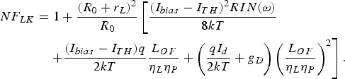
The DC photodetected current can be expressed as

To compare the noise figure to the electrical losses (inverse of the link gain), we plot them on the same figure. The measured noise figure of the IMDD link (NF LK) can be extracted from to the output noise power:

The theoretical and experimental results shown in Fig. 7 are obtained at the RF frequency of 3 GHz for a matched link and when the optical power of the laser is set to 14 dBm. One can notice that, similarly to a pure RF link, when the optical link is RF matched at its ends, the noise figure level remains above the electrical noise value.
Simulated level of noise figure compared to electrical losses.

V. ONP OF AN UNMATCHED MICROWAVE PHOTONIC LINK
A) Output noise power
In order to investigate the situation where the optical link is unmatched, we now turn the frequency to 2.7 GHz.
At this frequency, the opto-microwave link is mismatched only at the output of the photodetector. We verified experimentally this assumption by measuring at 2.7 GHz the input return loss of both DFB and LNA. They are found to be, respectively, equal to 16 and 14.2 dB. On the other hand, the photodetector output return loss is measured to be 1.4 dB.
Because of this mismatching load condition, photodetector thermal noise due to the conductance g D gives rise to a “new” reference level of thermal noise at the photonic microwave link output. The low value of g D, as compared to the inverse of generator resistance, implies that the ONP at 2.7 GHz is lower than the matched thermal noise, kTB. This unusual phenomenon is depicted in Fig. 8 for an optical power of 14 dBm.
Simulations (full lines) and measurements (dots) of ONPs in the case of an impedance matched link (at 3 GHz) and unmatched link (at 2.7 GHz).

B) Noise figure
Let focus on this peculiar situation where the link output impedance is mismatched. As with the matched link, we compute and measure the noise figure and the electrical losses versus detected photocurrent. The results are presented in Fig. 9.
Simulated (solid lines) and measured (dots) level of noise figure compared to electrical losses.

One can notice, on the left-hand side, that the noise figure becomes lower than the electrical losses when the DC photocurrent is below 0.3 mA. This result is thereby obtained theoretically and confirmed experimentally. It clearly evidences that an unmatched optical microwave link can present a lower noise figure than an electrical link exhibiting similar losses as already theoretically foreseen by Frigyes [Reference Frigyes6]. It is important to notice that in the field of pure RF, the noise figure can be lower than the inverse of the electrical transducer gain (or electrical losses) as soon as the passive attenuator presents a mismatched output.
Consequently, the ONP is lower than the input noise power, indeed, the link presents a gain-noise factor product less than 1. That is, if RIN, I d and g D are sufficiently low, the main contribution to the noise figure in relation (5) is related to the shot noise, which is proportional to optical losses, unlike the electrical signal which experiences the square of the optical losses. Furthermore, the noise figure can be defined as the ratio of the sum of all square noise current sources at the receiver of the link by the square noise current source at the receiver due to the thermal noise of the resistance of the generator. As g D is lower than the inverse of R 0, the noise figure can become lower than the electrical loss of the link (Fig. 9). This is the first time, to our knowledge, that this result is experimentally demonstrated and theoretically validated on a real photonic microwave link.
VI. CONCLUSION
In conclusion, we presented a simulation tool based on an accurate physical model embedded in a RF chain simulator. This simulation tool takes into account both optical and electrical characteristics of the link components such as the laser dynamics and impedance matching networks at the input and output of the optical link. It enabled us to get an accurate description of the optical link even under unusual operation conditions. In particular, we were able to expose an unusual behavior in which the noise figure of a microwave optical link can be lower than the electrical losses like in pure microwave links. This highly unusual situation is reached when the optical losses are high enough and when the optical link is impedance mismatched at its output. All the theoretical predictions are tested and confirmed on an IMDD link that we have specifically developed for this purpose. Further refinements include the development of accurate physical models taking into account the second- and third-order nonlinear behavior of the link.
ACKNOWLEDGEMENT
The authors would like to acknowledge Frédéric Van Dijk and Alain Enard from III-V Lab. Alcatel Thales for their kind help.
 Anne-Laure Billabert received the engineering degree in electronics from IRESTE, University of Nantes, France, and the DEA degree in electronics and radar from the University of Nantes, France, both in 1995. She received the Ph.D. degree in radar polarimetry field in 1999 from the University of Nantes, France. Since 1999, she has joined the ESYCOM laboratory and Cnam, Paris, France, as lecturer. Her current researches are centered in the topics of opto-microwave, mainly the simulation of opto-microwave link. She is responsible for the French photonic microwave club of the Société Française d'optique.
 Mourad Chtioui received the engineer degree in electrical engineering from the Ecole Superieure d'Electricite (SUPELEC), Gif-Sur-Yvette, France, in 2005, and the Ph.D. degree in 2008, from the Université des Sciences et Technolgies, Lille, France. From 2005 to 2008, he was at the Alcatel-Thales III-V Lab, in Marcoussis, France, where he was engaged in research on high-speed and high-power photodiodes. He joined Thales Air Systems in 2009 and is currently with the RF Distribution Department. His current activities include the design and development of microwave photonic links for radar applications. These researches include the design, simulation, characterization, and packaging of optoelectronic devices.
 Christian Rumelhard qualified as electronic engineer in 1966 and received a Docteur Ingénieur degree in 1977 (Paris-6 University). He worked at Thomson-CSF on the design of microwave tubes until 1969, on the design of hybrid microwave integrated circuits until 1975 and then he developed CAD algorithms and numerical models for the simulation of microwave circuits and devices. In 1980, he created an MMIC laboratory in the Central Research Laboratory of Thomson-CSF. In 1985, he was in charge of a design and characterization team in the Gallium Arsenide Department of this company. During the 1980–90 decade, tens of MMICs were designed and characterized in his different teams. This activity resulted in many communications and contributions to four different books on microwave circuits. In 1992, he became Professor in Conservatoire National des Arts et Métiers, Paris where he worked on simulation, design and measurement of microwave and photonic devices (SiGe HPT), circuits and systems. From 1997 to 2005, he was director of Equipe Systèmes de Communication et Microsystèmes (ESYCOM), a common research team between CNAM, ESIEE, and University of Marne-la-Vallée. In October 2000, he was general chairman of the 3rd European Microwave Week in Paris. He is now Professor Emeritus at CNAM.
 Catherine Algani received, from the University of Paris 6, France, the DEA degree in electronics, and the Ph.D. degree, respectively, in 1987 and 1990. Her dissertation concerns the area of active MMIC design using GaAs HBTs technology in CNET-Bagneux. In 1991, she joined the electronics engineering department and the LISIF Laboratory, at University of Paris 6, as a lecturer. From 1991 to 2005, she worked on the design of microwave and millimeter-wave integrated circuits on different GaAs technologies. In 1997, she began to work in the area of microwave photonics (optically controlled microwave switches on GaAs and electro-optic organic modulator). In 2005, she joined ESYCOM at CNAM-Paris, where she is currently a full professor. Her current research interests are the development of devices, circuits, and sub-systems for ultrahigh speed digital and analog communications for ROF and wireless applications. These researches include the modeling, the design, and the characterization of such structures.
 Mehdi Alouini received the B.S. degree in fundamental physics from the University of Rennes, Rennes, France, in 1995, the M.S. degree in optics and photonics from the Ecole Supérieure d'Optique, University of Paris XI, Orsay, France, in 1997, and the Ph.D. degree in laser physics from the University of Rennes in 2001. He was with Thales Research and Technology France, Palaiseau, from 2001 to 2009 as Research Engineer. Since then, he joined the University of Rennes as associate professor at the Institut de Physique de Rennes and consultant at Thales Research and Technology. His main activities cover the modeling and optimization of microwave photonics systems as well as active polarimetric and multispectral imaging. His research interests are also in solid-state and semiconductor laser physics. Dr. Alouini is a member of the Société Française d'Optique, the EOS and the OSA.
 Quentin Levesque, born in 1987, has a bachelor's degree in science from Ecole Supérieure de Physique et de Chimie Industrielle (ESPCI) and he is a student in last year at the Institut d'Optique Graduate School. He was involved in this study like intern at Thales in the TR6 staff.
 Christophe FEUILLET was born in 1974. He received, in 1995, undergraduate technology degree in “Electrical Engineering and Industrial Computing” from University of Ville d'Avray with a complementary degree of microwaves and aerospace telecommunication. He received the degree in electrical engineering from the Superior National School of Electronic and his Application (ENSEA), Cergy Pontoise, in 2006. At this time, he joined the THALES Group in Photonics Department where he has been involved in several projects in the field of Microwave Photonics interfaces for RADAR applications in FM, L, S, and X band.
 Alexandre MARCEAUX was born in 1975. He received his micro-optoelectronic and materials engineer degree and his Ph.D. in optoelectronic from the Institut National des Sciences Appliquées (INSA), Rennes, France in 1998 and 2001, respectively. From 1998 to 2001, he was at the Laboratoire de Physique du Solide (LPS) at the INSA Rennes, where he was engaged in research on ultrafast Fe-doped InP MQWs saturable absorber micro-cavities for all-optical 2R regeneration. He joined Thales Research and Technology in 2001 and the Alcatel-Thales III-V Lab in 2005 as research staff member, where he was in charge of the development of photodetectors for microwave photonic applications. He moved to Thales Air Systems in 2006 and is currently with the RF Technical Unit. His current activities include optical distribution for radars signals, packaging of optoelectronic devices, and optical sensors. He has authored several papers in referred journals and conference proceedings.
 Thomas Merlet graduated from Ecole Supérieure de Physique et Chimie Industrielles de Paris, France, and received the Ph.D. degree in optics and photonics from Paris University XI, Orsay, France. In 1994, he joined the Optics group at Thomson-CSF Corporate Research Laboratory, Orsay, France. He was involved in microwave photodetectors research. Since 1997, he joined the RF Department of Thales Air Systems. He has grown and managed the microwave photonics group and is acting since 2007 as a Technology and Innovation Manager.



