I. INTRODUCTION
Ultra-wideband (UWB) systems, due to a high transmission rate, high-resolution, and low-power consumption, have created a revolution in the field of short-range telecommunication and radar-based imaging systems. Antennas are an essential part of a UWB system and play an important role in system capabilities. UWB antenna design, including features such as low-cost, small-size, and omni-directional radiation patterns, are easily possible. However, the design of a compact-sized antenna with a directive radiation pattern, high-gain, and low distortion in the time-domain remains difficult to achieve. A tapered slot antenna (TSA) is a planar traveling-wave antenna with end-fire radiation that gives good directivity and gain, good cross-polarization, wide bandwidth, and easy construction. This antenna was first introduced by Gibson [Reference Gibson1], by which it was also known as the Vivaldi antenna, and many improvements to the initial design have been proposed since its introduction [Reference Ponchak, Jordan and Chevalier2–Reference Wu, Zhao, Nie and Liu8]. In [Reference Ponchak, Jordan and Chevalier2, Reference Cheng, Hong and Wu3], a dual exponential TSA (DETSA) and dual V-type linear TSA (DVLTSA) were investigated. A simple design of a TSA using CPW for wide-slot transition was presented in [Reference Kim and Jung4]. This antenna exhibited a compact size and good gain, but its impedance bandwidth and radiation efficiency were low. A miniaturized TSA, using a folded balun on the radiator, was proposed by Zhu et al. [Reference Zhu5]. In [Reference Ebnabbasi, Busuioc, Birken and Wang6, Reference Ebnabbasi, Sczyslo and Mohebbi7], a new method for the design of the flare's opening rate for a TSA was presented, and its UWB performance was evaluated. This method was based on a stepped quarter-wave Chebyshev transformer. In [Reference Wu, Zhao, Nie and Liu8], by using a new stepped-connection structure between the slot-line and tapered patches, a Vivaldi antenna with good bandwidth and compact size was introduced.
TSA can theoretically have unlimited bandwidth. But in practice, the microstrip to slot-line transition structure limits the high-end operating band. In addition, the width of the tapered flares limits the low-end operating band. The limitation of transition was later overcome in the antipodal Vivaldi antenna (AVA) introduced in [Reference Gazit9]. In recent years, several efforts have been made to optimize these antennas [Reference Abbosh10–Reference Moosazadeh and Kharkovsky15]. By using a high permittivity substrate and modification of the microstrip-fed structure, the physical size of the antenna was reduced [Reference Abbosh10]. In [Reference Fei, Jiao, Hu and Zhang11, Reference Bai, Shi and Prather12], antenna size reduction and improvement of low-end radiation characteristics were performed using a tapered slot edge (TSE) technique. Generally, corrugated edge structures improve the performance of low frequencies. Pandey et al. [Reference Pandey, Verma and Meshram13] proposed a novel compact AVA in the frequency range of 2–12 GHz. However, its realized gain and efficiency were low. Recently, a CPW-fed AVA with good radiation performance in the lower band was presented [Reference Wang, Yin, Wu and Lian14]. In [Reference Moosazadeh and Kharkovsky15], a modified compact AVA was proposed with a frequency band between 3.4 and 40 GHz. Despite AVA's worthwhile features, the inherent problem with AVA remains bad cross-polarization, especially for higher frequencies, due to the skew of the slot fields. By adding another layer to the AVA, a balanced antipodal Vivaldi antenna (BAVA) was created [Reference Langley, Hall and Newham16], which offered low cross-polarization, but increased the complexity and cost, while also suffering from tilted beams. Molaei et al. [Reference Molaei, Kaboli, Mirtaheri and Abrishamian17] reported a new BAVA that overcame the tilted beam problem by applying a dielectric lens in front of the antenna's aperture.
One of the challenges of TSA design lies in its feeding structure. As mentioned, except for the limitation of transition, TSA performance is similar to AVA. Moreover, TSA cross-polarization remains very low. Therefore, the primary goal of this paper was to overcome the limitations in high and low-end bandwidth and increase the efficiency of the original TSA antenna, to maintain the good features of both TSA and AVA antennas. In this study, we presented a modified CPW to slot-line transition. In the proposed design, the bandwidth of the transition was greatly enhanced by connecting one of the CPW arms to a broad-band open radial stub. Moreover, by adding an air-bridge and employing TSE structure, the performance of the antenna was increased effectively in the lower frequencies. The antenna structure is presented in Section II. The results and discussion are described in Section III, and conclusions follow in Section IV.
II. ANTENNA STRUCTURE
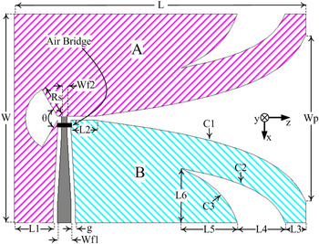
Configuration of the proposed TSA is shown in Fig. 1. A Rogers RO4003C dielectric was used as the substrate with a relative permittivity of 3.38. The thickness of the substrate and the copper layer were 0.508 and 0.07 mm, respectively. The dimensions of the antenna were set to be 50 × 70 mm2 (0.43 × 0.61 λ; where λ is the wavelength of the low-end operating frequency). In the proposed antenna, CPW was used as a feed line with a width of 2 mm, and a slot-line gap width of 0.2 mm, which its characteristic impedance matches with a 50 Ω, coaxial line. Moreover, as shown in Fig. 1, the CPW center line width decreases linearly to 0.4 mm and acts as an impedance transformer for impedance matching between the CPW and the slot-line (82 Ω). The exponential profile curvatures indicated by C 1, C 2, and C 3 in Fig. 1 can be described by:
 $$C_i :\;x = A_i e^{R_i z} + B_i \quad i{\rm :}\;1,\;2,\;{\rm and}\;3,$$
where A i , Ri , and B i are the scaling factor, exponential rate, and offset value, respectively.
Geometry of the proposed antenna.

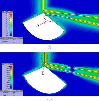
In the conventional microstrip to slot-line transition, two radial stubs, or circles, at opposite sides of the substrate were used for modeling the slot-line termination as an open circuit and the microstrip-line as a short circuit. However, in this paper, similar to [Reference Ho and Hart18, Reference Hettak19], we used only one radial stub at the end of the CPW single arm that acts as a broad-band open circuit. In previous works, this radial stub, or circle hollow, located asymmetrically with respect to the tapered flares, led to instability and deviation of the radiation pattern at different frequencies, and also limited the impedance bandwidth. To solve this problem in our proposed antenna, the radial stub was located symmetrically, which caused the radiation pattern to be symmetrical and stable across the frequency band. Results showed that as the radius of the radial stub became larger, the return loss performance at the low and middle frequencies was better, but the high-end operating frequency decreased. Consequently, there was a trade-off. On the other hand, in the proposed CPW antenna, a cross-section of tapered flares on each side of the slot (shaded A and B areas in Fig. 1) were not symmetrical or exactly the same. Because the electrical length of the two tapered flares was different, the waves propagated through them at different distances. This difference caused CPW-slot-line mode-conversion, and the experience of an unwanted current distribution and disturbance of current around the radial stub (region A in Fig. 2(a)). To overcome this problem, we applied an air-bridge in the vicinity of the radial stub to connect the two tapered flares together (Fig. 1). The air-bridge exhibited a short circuit for the slot-line mode [Reference Ma, Qian and Itoh20], and it united the two parts. This technique omitted the disturbance of current by directing the current toward the tapered flares, as shown in region B in Fig. 2(b).
Simulated current distribution of the antenna: (a) Without an air-bridge; (b) With an air-bridge.

Important advantages of the proposed transition were its simple design, low fabrication costs, uni-planar structure, low-wave propagation dispersion up to very high frequencies, and independence of via-holes. Therefore, it was preferable to MMIC technologies. Moreover, microstrip was sensitive to the substrate thickness, while CPW was not. To further improve the lower frequency characteristics, we employed a TSE structure (Fig. 1). This increased the electrical length of the antenna and decreased the low-end operating frequency. The length of the slot was chosen to be approximately 0.15 λ according to [Reference Fei, Jiao, Hu and Zhang11]. Simulation results showed that increasing the number of slots does not have much effect on the performance of the antenna. Therefore, we applied only one TSE in our design.
III. RESULTS AND DISCUSSION
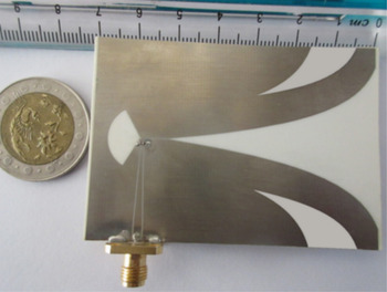
Simulations were performed in the CST Microwave Studio environment. After optimization, the final dimension values are listed in Table 1. Moreover, the exponential curvature parameters are listed in Table 2. To validate the results, a prototype of the proposed antenna was fabricated as shown in Fig. 3. A SubMiniature version A (SMA) connector was used to feed the antenna.
Fabricated prototype of the antenna.

Optimal dimension values.

Exponential curvatures parameters.

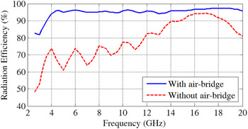
For further comparison, the radiation efficiency for both designs (with and without the air-bridge) is illustrated in Fig. 4. The plot shows that without an air-bridge the radiation efficiency is lower than 80% across a wide range of frequencies. On the other hand, adding the air-bridge increased the efficiency to more than 96% across almost the entire working frequency band. Instead of using an air-bridge, we also could connect two tapered flares at the other side of the substrate using via-holes. However, this technique increased both the complexity and cost of construction, while at higher frequencies the propagation characteristics of the via-holes have a stronger electromagnetic effect on the performance of the antenna that leads to gain reduction. Therefore, the air-bridge technique was a better choice.
Radiation efficiency of the antenna with and without an air-bridge.

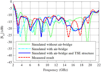
The measured and simulated return loss in three situations, either with or without an air-bridge and employing a TSE structure, are shown in Fig. 5. As shown in the figure, the low-end operating band decreased from 4.2 to 3 GHz, due to the presence of the air-bridge, and from 3 to 2.6 GHz as a result of employing the TSE structure. However, the high-end operating band was also reduced a little, though that is not significant (20 GHz). The measured result was in good agreement with the simulated results, but there was some deviation, perhaps due to multiple reflections caused by the SMA connector, the soldering process, or fabrication errors. Extra simulation results showed that the width and height of the air-bridge does not have much influence on the overall performance of the antenna. However, the air-bridge worked better when it was not very close to the surface.
Measured and simulated return loss (S 11).

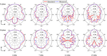
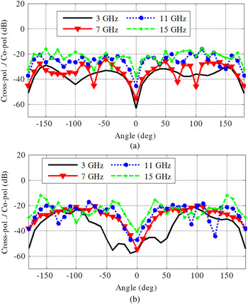
Figure 6 shows the measured and simulated E- and H-plane radiation patterns at different frequencies. The figure reveals that the antenna exhibited good end-fire radiation properties and good stability with frequency variations. However, as expected, directivity increased with each frequency increment. The measurements confirmed the simulations. Since cross-polarization components were very small in some directions, the ratios of cross-polarization to co-polarization in the E- and H-planes for different frequencies are presented in Fig. 7. As shown in Fig. 7, in the propagation direction (z-direction in Fig. 1), this ratio is lower than −25 dB in all frequencies. In the lower frequencies, the ratio is even better (less than this value). In addition, these ratios, in other directions, were on average lower than −20 dB, which confirms the performance of the proposed antenna.
E-plane (xoz) and H-plane (yoz) radiation patterns of the antenna at different frequencies.

Cross-polarization to co-polarization ratio: (a) E-plane; (b) H-plane.

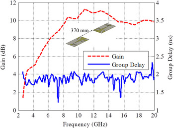
Realized gain and group delay variations, according to frequencies, are shown in Fig. 8. The gain increased rapidly in low frequencies; for example, the gain values for the frequencies 3, 5, and 6 GHz are 4, 6, and 7.9 dB, respectively. At frequencies greater than 8 GHz, the gain values are nearly 10 dB. The maximum gain was 11.3 dB at 10.8 GHz, which is high for a compact-size antenna. To verify the time-domain characteristics, two prototype antennas were located over a distance of 370 mm in the face-to-face position. For optimal wave transmission and reception, the antenna must exhibit non-dispersive behavior, which corresponds to phase linearity and constant group delay. The group delay was investigated in Fig. 8. As the results show, the measured group delay was about 1.8 ns with the variations of ±0.4 ns in most frequencies, which describes the low distortion of the received signal in respect to the transmitted signal across the whole working frequency band.
Realized gain and group delay versus frequencies.

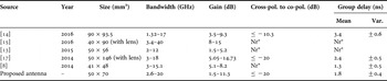
To compare the performance of the proposed antenna with recently published research that described other antennas, we have summarized the results in Table 3. According to this table, our proposed antenna presents an acceptable bandwidth and gain in comparison with others. Although the proposed antenna in [Reference Wang, Yin, Wu and Lian14] shows comparable bandwidth and even better gain in lower frequencies than our antenna, it has worse cross-polarization to co-polarization values. The proposed BAVA antenna in [Reference Molaei, Kaboli, Mirtaheri and Abrishamian17] showed very good time and frequency characteristics. The gain in [Reference Molaei, Kaboli, Mirtaheri and Abrishamian17] was better than our gain, but the antenna's size was much bigger, and comprised a complicated three-layer structure. The proposed antennas in [Reference Wu, Zhao, Nie and Liu8, Reference Pandey, Verma and Meshram13] were smaller in size, but they presented worse bandwidth and gain in comparison with ours. Moreover, the cross-polarization value was not reported in either of those studies [Reference Wu, Zhao, Nie and Liu8, Reference Pandey, Verma and Meshram13]. The proposed AVA antenna in [Reference Moosazadeh and Kharkovsky15] had the broadest bandwidth, as shown in Table 3, but its low frequency was higher than others. Unfortunately, the parameters of group delay and cross-polarization were not evaluated in that study [Reference Moosazadeh and Kharkovsky15]. Therefore, our proposed antenna presented not only acceptable frequency characteristics in a medium compact size but also provided good group delay and cross-polarization to co-polarization values. However, the drawback of our proposed antenna was its low gain within the low-end frequency band.
Summary of the results in recently published literature.

Nr*, not reported.
IV. CONCLUSION
In this study, we proposed a miniaturized CPW-fed TSA with a TSE structure. In this new proposed design, rather than using a conventional microstrip to slot-line transition, a modified CPW to slot-line transition with an air-bridge was employed. The proposed antenna has a compact size of 50 × 70 mm2. The results of simulations and measurements showed that the antenna offers broad bandwidth impedance (2.6–20 GHz), good directivity, good gain, and low cross-polarization. A measured group delay showed that the performance of the antenna was satisfactory in the time-domain. All these properties make this antenna suitable for UWB applications, particularly for microwave imaging systems.
 Alireza Hokmabadi received the B.Sc. degree in electrical communication engineering from Shahid Bahonar University, Kerman, Iran, in 2006 and the M.Sc. degree in communication field and wave engineering from Tarbiat-e-Modarres University, Tehran, in 2009. He is currently working toward the Ph.D. degree in the Faculty of Engineering and Technology, Imam Khomeini International University, Qazvin. His research interests include electromagnetic, radar, bio-electromagnetic, and antenna.
 Asghar Keshtkar received the B.Sc. degree in electrical engineering from Tehran University, Tehran, Iran, in 1989; the M.Sc. degree in electrical engineering from the University of Khaje-Nasir, Tehran, in 1992; and the Ph.D. degree in electrical engineering from Iran University of Science and Technology, Tehran, in 1999. He is currently a Full Professor with the Faculty of Engineering and Technology, Imam Khomeini International University, Qazvin, Iran. His research interests include electromagnetic, electromagnetic launcher, bio-electromagnetic, and antenna.
 Alireza Bayat received the B.Sc. degree in communication engineering from Andhra University, Visakhapatnam, India, in 1987; the M.Sc. and the Ph.D. degree in communication engineering from the University of IIT Banaras Hindu, Varanasi, India, in 1989, 1992, respectively. He is currently an Assistant Professor with the Faculty of Engineering and Technology, Imam Khomeini International University, Qazvin, Iran. His research interests include electromagnetic, radar, bio-electromagnetic, and antenna.
 Ahmad Keshtkar received the B.Sc. degree in applied physics (solid state) from Shahid Beheshti University, Tehran, Iran; the M.Sc. degree in medical physics from Tarbiat-e-Modarres University, Tehran; and the Ph.D. degree in medical physics and engineering from the University of Sheffield, Sheffield, UK, in 2004. He is a Full Professor with the Medical Physics Department, Tabriz University of Medical Sciences, Tabriz. His major field of study is on tissue characterization using electrical impedance spectroscopy. Dr. Keshtkar is a member of the Iranian Association of Medical Physicists.