Introduction
With the approval of commercial usage from the Federal Communication Commission, within the 3.1–10.6 GHz frequency band, the lltra-wideband (UWB) communication technology gained substantial research focus [1, Reference Panda, Kakumanu and Kshetrimayum2]. However, along the commercially available UWB frequency bands exist many narrowband applications such as Wi-MAX, WLAN, etc, which can potentially cause interference and should be eliminated [Reference Li, Hei, Feng and Shi3, Reference Tang and Lin4]. This could possibly be achieved by integrating band-notch characteristics within the antenna, rejecting the interfering bands. Various designs have been listed in the literature showing band-reject characteristics. In references [Reference Ranjan and Tripathi5, Reference Ranjan6] an open loop resonator structure is used along with a stub to generate a band notch filtering response. This approach leads to distortions in the antenna gain as well as radiation characteristics due to the interference produced by the filter. Some more techniques of realizing a band notch filtenna presented are vertical integration of differential resonators [Reference Chao-Tang and Shyh-Jong7], introduction of shorting pins [Reference Wu, Pan, Hu and Zheng8], open circuited stubs as well as parasitic elements or strips [Reference Hu, Pan, Zhang and Zheng9], and multiple stubs loaded feed structure. Most of the techniques listed are complex in nature and could possibly make the design nonplanar. Another approach to realize a band notch characteristic is introduction of band-reject filtering structure within the feeding circuit of the antenna. This method can make the design more compact and could lead to lower insertion loss values.
In communication system, everyone is aware of the adverse effects of multipath fading. Multiple-input–multiple-output (MIMO) technique was an effective alternative to combat multipath fading by coherently aggregating the multipath signals produced at the receiver, which leads to efficient spectrum utilization as well as channel capacity [Reference Ordentlich and Erez10]. Hence, by integrating the MIMO as well as UWB technologies we can surely achieve high data rates, low consumption of power, and also can communicate effectively to a large distance [Reference Hussain and Sharawi11–Reference Gao, He, Wei, Xu, Wang and Zheng15]. However, all the above reported works [Reference Ranjan and Tripathi5–Reference Hu, Pan, Zhang and Zheng9] do not employ MIMO functionality which is an important aspect of modern wireless communication. Various UWB-MIMO antennas with band-reject features having orthogonal placement of elements, are reported in the literature as well. In reference [Reference Rajkumar, Selvan and Rao16] a 4 × 4 MIMO is loaded with dual complimentary split-ring resonator structures obtaining notches in WLAN and Wi-MAX frequency band. In refernce [Reference Eltrass and Elborae17] the microstrip radiator is etched with a C-like structure acting as a stub, and the feedline is loaded with two U-slots for getting dual notches. A triple band-reject response with the help of defected structure as well as pie-structured slot is achieved in the patch based UWB filtenna [Reference Li, Li and Ye18]. Introduction of H-L-like slots within the microstrip based radiator for achieving three band notches and an additional decoupling structure for isolation is designed to make a 4 × 4 MIMO filtenna with maximum gain of 4.6 dB [Reference Tang, Wu, Zhan, Hu, Xi and Liu19]. These literatures are more dedicated toward the isolation enhancement and size miniaturization of the UWB-MIMO filtennas. Also, the peak gain and S11 in the rejected band is not discussed, which is a measure of how efficiently the band is rejected by the antenna. It has been also observed that very less work has been done targeting the frequency range 1 (FR1) (4.1–7.125 GHz) range of frequency which is an important frequency band as this range of frequency are used to carry most of the fifth-generation cellular mobile communication traffic.
In this work, a compact, simple structured two-port MIMO antenna with band notch characteristics is proposed. The proposed MIMO design is made by the integration of two UWB filtenna in an antiparallel manner where the UWB filtenna is made up by combining an UWB antenna and a band-reject filter (BRF). The proposed MIMO filtenna provides radiation characteristics in FR1, i.e., from 4.1 to 7.125 GHz, while the BRF attenuates frequencies from 3 to 3.42 GHz (Wi-MAX) with excellent rejection. The device’s simulation results are achieved concerning characteristics like insertion loss, reflection coefficients, radiation patterns, efficiency, etc. To achieve good isolation, we inserted a metal strip with three identical square-shaped structures equidistant from each other, resulting in a significant enhancement in the isolation parameter (S21). MIMO parameters like envelope correlation coefficient (ECC), diversity gain (DG) are also simulated and studied. The design process and performance analysis for MIMO filtenna, along with the UWB antenna and the filter, are covered in the following sections.
Proposed 2 X 1 MIMO filtenna design methodology
The proposed dual-port MIMO filtering antenna is shown in Fig. 1(a) which combines two UWB Filtennas in antiparallel configuration. The structure has been made up on FR4 substrate because of its commercial availability and cost-effectiveness. The thickness of the substrate is kept at 1.6 mm with the dielectric constant of 4.4 and a loss tangent of 0.02. The optimized MIMO antenna configuration was obtained by keeping the respective single-port filtennas in different configurations viz. (i) antiparallel, as shown in Fig. 1(a), (ii) parallel, as observed in Fig. 1(b), and (iii) orthogonal, which is depicted in Fig. 1(c). Since the antiparallel configuration showed the optimum S11 parameter response in the desired frequency range, as depicted in Fig. 1(e), therefore this configuration is selected. The bottom view of the final antenna design is shown in Fig. 1(d) which utilizes a defected ground structure for better impedance bandwidth and further copper reduction. The comparison of S11 versus frequency curve for different antenna element orientations is given in the Fig. 1(e). Table 1 shows the dimensions of the optimized structure.
Top view of designed 2 × 1 MIMO filtenna (a) antiparallel (180°) (proposed design) (b)parallel (0°) (c)orthogonal (90°) configuration (d) bottom view (e) comparison of S11 parameters for different orientation configurations.

Dimensions of dual-port MIMO filtenna

Since, as stated above, the proposed design is made by combination of components like the UWB antenna, the BRF, and the UWB filtenna, the stepwise design and analysis of each design is discussed in the following sections.
Step 1: Single port UWB antenna design
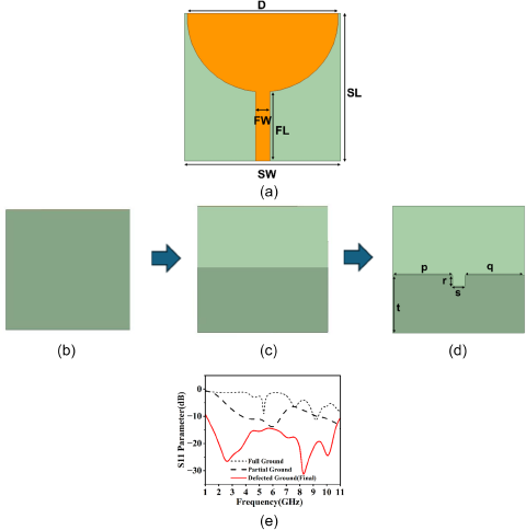
Figure 2(a) shows the top view of the single-port UWB antenna. The antenna operates in UWB i.e., from 1 to 11 GHz (Fig. 2e), with an antenna dimension of 31 × 32 × 1.6 mm3. The top layer consists of a semicircular-shaped metal patch, with a radius of 15 mm, as a radiating element that is excited through a 50-Ω microstrip feeding line. The width of the 50-Ω microstrip feedline is 3 mm. The antenna performance is simulated for various configurations of the ground plane, i.e., full ground (Fig. 2[b]), partial ground (Fig. 2[c]), and defected ground as shown in Fig. 2(d). But it is evident from Fig. 2(e) that the defected ground structure is showing the optimum reflection coefficient performance, therefore this configuration is selected. Table 2 is showing the dimensions of both the antenna and the selected configuration of ground plane.
(a)Top view of UWB antenna and, different configurations of ground plane (b) full ground (c) partial ground (d) defected ground (proposed), and (e) comparative S11 curve for different ground configurations.

Dimensions of UWB antenna (units:mm)

Step 2: Band Reject Filter design
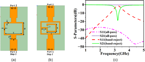
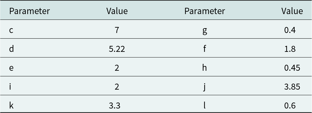
Figure 3(a) shows the filter design working as an all-pass filter in step 1. In step 2, a stub has been inserted in shunt to achieve band-reject functionality as shown in Fig. 3(b). The electrical length of the stub can be adjusted to change this band-notch frequency [Reference Alam, Thummaluru and Chaudhary20]. Since this filter is to be incorporated within the microstrip line of the UWB antenna, therefore the width of the feedline of filter is kept as 3 mm. The graph of S-parameters of all-pass filter is displayed in Fig. 3(c) which depicts the filter is working as an all-pass filter. From Fig. 3(c) it is evident that the BRF is rejecting the frequency ranging from 3 to 3.42 GHz having resonant frequency as 3.2 GHz. The S11 of BRF is calculated to be −1.22 dB and S21 is found as −18.86 dB at resonance. Table 3 shows the dimensions of the filter.
Structural representation of (a) all-pass filter (b) band-reject filter, (c) combined S-parameters plot of both all-pass and band-reject filter.

Dimensions of filter (units:mm)

Step 3: Single port UWB filtenna
Figure 4(a) shows the top view of UWB filtenna which was made by combining UWB antenna and BRF as discussed above. The patch’s semicircular shape serves as a radiating component. Poor matching occurs in the intended UWB range for the antenna when the BRF is immediately replaced with the feedline of the antenna. The ground plane and the integrated filter’s length are further optimized to get the desired result. Figure 4(b) shows the bottom view of the filtenna. The filtenna is having overall dimensions of 31 × 32 × 1.6 mm3 which, because of its small and straightforward structure is very easy to fabricate and is very compact in size. The simulated reflection coefficient and gain of filtenna is shown in the Fig.4(c) and (d), respectively.
(a) Top view and (b) bottom view of single port UWB filtenna, (c) S11 (d) gain vs frequency curve, and (e) radiation pattern plot at 4.12 GHz.

The current distribution diagram is depicted in Fig. 5, at three different frequencies i.e., at 4.1, 3.2, and 9.65 GHz. The frequency 4.1 GHz is the resonant frequency where we are getting optimum S11 i.e., −31.67 dB, 3.2 GHz is the rejecting frequency with S11 value of −1.12 dB, and 9.65 is the out of band frequency but S11 value is lower than that obtained in the rejecting band. The surface current density is decreasing in the sequence of decreasing S11 values mentioned above, depicting antenna’s resonant behavior.
Surface current distribution at (a) resonant frequency (4.1 GHz), (b) notch resonant frequency (3.2 GHz), and (c) out of band frequency (9.65 GHz).

Figures 4(c) shows the S parameter of filtering antenna which is covering the entire UWB range except the 3.2 GHz frequency because of the BRF’s functionality. It is seen from the results that filtenna is showing peak resonating frequency at 4.12 GHz and S11 is calculated as −31.67 dB while at 3.2 GHz notch frequency, S11 is calculated as −1.12 dB. It is seen from the Fig. 4(d) that the peak gain of rejected frequency band is found to be −15 dB at 3.2 GHz, which depicts good rejection at the notch frequency, and at entire UWB range the average gain is around 2.5 dB. Polar plot radiation pattern at 4.12 GHz (both E-plane and H-plane) is shown in Fig. 4(e). The E-plane pattern shown in Fig. 4(e) shows bidirectional behavior at frequency 4.12 GHz whereas, the H-plane shows almost an omnidirectional pattern. Table 4 shows the dimensions of UWB filtenna.
Dimensions of UWB filtenna (units-mm)

Results and discussion
The proposed two-port MIMO filtenna prototype is fabricated and measured as shown in Figs. 6 and 7. Detailed description and analysis of the filtenna performance is as follows:
Combined simulated vs measured S-parameters curve of fabricated prototype (a) S11, (b) S21/S12, and (c) S22.

Photograph of fabricated antenna’s (a)top view (b) bottom view.

Simulated vs measured S-parameters
The comparison between simulated and the measured S parameters of filtenna is displayed in the Fig. 6(a–c). The S11 is found to be <−10 dB in the targeted frequency range (FR1 i.e. 4.1 to 7.125 GHz)) with measured isolation is below −20 dB for most of the band and it is clear from the below figures that the measured results is similar to simulated results ensuring the filtenna is suitable for practical applications.
Gain and radiation pattern
It is observed from the Fig. 8(a) that gain of the proposed design came out to be above 3 dB with average gain came out to be around 3.74 dB at the desired frequency of FR1. At 5.7 GHz, the value of gain is 4.36 dB. Figure 8(a) shows that the graph of measured gain is following the simulated one which is very good for practical applications. Figure 8(b, c) shows the simulated radiation pattern (E/H Plane) at 5.71 and 4.23 GHz respectively. The E-plane (Φ = 0) is depicting a bidirectional or eight-shaped radiation pattern, showing monopole type radiation. The principal plane (E-plane) pattern is consistent with frequency as shown in Fig. 8(b, c). The H-plane pattern is showing a directional behavior as compared to the single port antenna, without filter, pattern depicted in Fig. 4(e). The H-plane pattern shown in Fig. 8(b, c) shows distorted omnidirectional pattern at both the frequencies. This distortion occurs due to the higher order mode generation which hinders the uniform current distributions. This leads to more electromagnetic interference among the different modes [Reference Sediq, Nourinia and Ghobadi21]. These unwanted distortions could be further reduced by applying various methods like use of periodic structures, parasitic radiators, etc [Reference Rahman, Khan and Imran22].
(a) Measured and simulated gain of the fabricated prototype, (b) simulated radiation pattern (E/H plane) at 5.7 GHz, and (c) 4.23 GHz.

Radiation efficiency
Radiation efficiency is essential for ensuring antenna’s performance. Figure 9 shows the radiation efficiency of the filtenna. For the proposed MIMO filtenna, over 90% radiation efficiency is attained across the operational band, which is quite good.
Radiation efficiency curve of the proposed MIMO design.

Isolation enhancement
As was previously said, a significant amount of space must exist between components within the same MIMO system in order to provide simultaneous signal transmission and reception without compromising the antenna’s performance [Reference Sharma, Tiwari, Singh, Kumar and Kanaujia23]. We inserted an isolation strip with three identical square structures equidistant with each other in order to reduce the interference among the two element’s radiation which can be observed from the surface current distribution as depicted in Fig. 10(c). In addition, antiparallel orientation of the corresponding elements are applied in order to achieve polarization diversity which in turn enhances the isolation which can be observed from Fig. 10(a, b). Figure 10(a–c) depicts the reduction in the amount of surface current with the change in orientation of the antenna elements as it increases the port spacing as well as changes the field direction of the second element, thus enhancing the isolation, also further enhancement takes place with the introduction of isolation strip. It can be observed from Fig. 11 that S21 without isolation came out to be ∼−16 dB while with inserting a strip isolation comes to below −20 dB in the desired frequency range which is acceptable and supports the current distribution outcomes from Fig. 10(a–c).
Surface current distribution at resonant frequency for (a) parallel orientation, (b) antiparallel orientation, and (c) proposed MIMO antenna with isolation line.

S21 parameter with and without isolation structure of proposed MIMO filtenna in antiparallel configuration.

Study of MIMO parameters
A MIMO antenna’s quality can be determined by a few diversity parameters in addition to S-parameters and radiation properties. In real applications, the MIMO antennas have to meet the predetermined values of the diversity parameters because each parameter is essential in determining the antenna’s performance. The performance of MIMO filtenna systems can be better understood by carefully examining these factors, which will help to enhance wireless communication technologies. Thus, this section discusses some fundamental diversity characteristics for MIMO antennas.
Envelope correlation coefficient (ECC)
In a MIMO system, the correlation between the envelopes of the signals received by various antennas is measured by the ECC. A low ECC (almost 0) is preferred as it suggests that the signals received by various antennas are comparatively independent of one another. Figure 12 shows that the ECC value in the FR1 range is almost 0.0025.
MIMO parameters: ECC and DG curves for the proposed MIMO filtenna.

The mathematical expression of ECC is given by equation (1)
 \begin{equation}{{{\rho }}_{\text{S}}} = \frac{{{{\left| {{\text{S}}_{11}^{\text{*}}{{\text{S}}_{12}} + {\text{S}}_{21}^{\text{*}}{{\text{S}}_{22}}} \right|}^2}}}{{\left( {\left( {1 - \left( {{{\left| {{{\text{S}}_{11}}} \right|}^2} + {{\left| {{{\text{S}}_{21}}} \right|}^2}} \right)} \right)\left( {1 - \left( {{{\left| {{{\text{S}}_{22}}} \right|}^2} + {{\left| {{{\text{S}}_{12}}} \right|}^2}} \right)} \right)} \right)}}\end{equation}
Diversity gain (DG)
The diversity gain in wireless systems serves as an indicator of the performance and dependability of a MIMO antenna. Therefore, the DG of the MIMO antenna must be high (approximately 10 dB) within the operating frequency range. Higher diversity gain indicates better resilience to fading and improved communication reliability. In our proposed design, Fig. 12 shows DG close to around 10 dB which is desired. The DG can be calculated using ECC value and is given by the equation (2)
 \begin{equation}{\text{DG}} = 10\sqrt {\left( {1 - {{\left| {{{{\rho }}_{\text{S}}}} \right|}^2}} \right)} \,\,\,\,\end{equation}
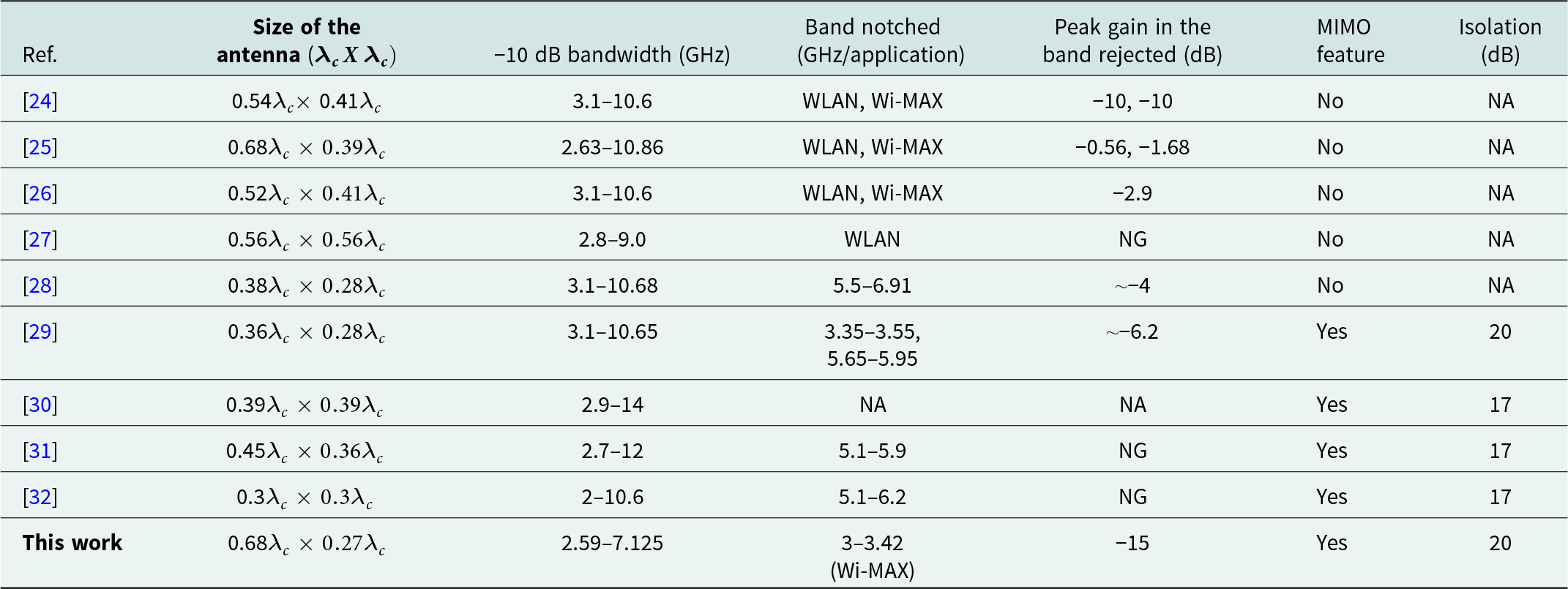
Table 5 shows the comparison between different band-notch antenna approaches reported in different literatures. The proposed filtering antenna with overall area 0.18  ${{\boldsymbol{\lambda }}_{\boldsymbol{c}}}^2,$ is compact as compared to almost all the tabulated designs. Also, the presented filtenna rejects the 3–3.42 GHz band with peak gain of −15 dB which signifies how effectively the proposed filtenna is rejecting the Wi-MAX band. Also, the designed filtenna depicts MIMO feature, which is a significant attribute for an antenna in various wireless applications, not shown in almost all the listed filtenna designs except a few [Reference Li, Hei, Subbaraman, Shi and Chen29–Reference Tripathi, Mohan and Yadav32]. The isolation performance of the proposed antenna is within the acceptable level and shows better isolation values than most of the listed works.
Comparison with different band-notch filtenna approaches reported in the literature

*NA = not applicable, NG = not given,  ${{{\lambda }}_{\text{c}}}$ = cut-off wavelength.
Conclusion
This paper discusses design, simulation and fabrication of an efficient, compact sized dual-port MIMO filtenna of dimensions  $0.68{\lambda _c}{ } \times { }0.27{\lambda _c}{ } \times { }0.01{\lambda _c}{ }m{m^3}$. The proposed design covers FR1 and sub-6 GHz frequency band (<6 GHz). The design is fabricated on a low cost FR4 epoxy substrate. The design is showing good isolation (<−20 dB) as well as better gain performance with average gain of 3.74 dB in the desired full frequency range. The device is fabricated and measured. The simulated and measured results show good agreement thus, making it suitable for practical applications. The values of MIMO parameters like ECC, DG, CCL, and TARC show good MIMO performance. This proposed design is quite useful in 5G wireless systems and can also be useful in carrying cellular mobile communications traffic and at 5.7 GHz frequency range which is falling under sub-6 GHz frequency and at the same time reduces the interference from the Wi-MAX frequency band.
Data availability statement
The datasets generated during and/or analyzed during the current study are available from the corresponding author on reasonable request.
Authors’ contributions
All authors contributed to the study conception and design. Conceptualization and Methodology [Jeet Dewangan, Smriti Agarwal]; Simulation and Writing - revised draft preparation: [Jeet Dewangan]; Analysis and Investigation: [Jeet Dewangan, Yajush Rai]; Supervision and final check: [Smriti Agarwal]
Funding statement
The authors declare that no funds, grants, or other support were received during the preparation of this manuscript.
Competing interests
The authors have no relevant financial or nonfinancial interests to disclose.

Yajush Rai born in Varanasi (U.P.), India, in 1993. He is a research scholar in the Electronics and Communication Engineering Department at Motilal Nehru National Institute of Technology Allahabad, Uttar Pradesh, India. He completed his Master’s degree (M. Tech) in Electronics and Communication Engineering from the University of Allahabad, India in 2020 and his Bachelor’s degree in Electronics and Communication Engineering from Raj Kumar Goel Institute of Technology (R.K.G.I.T) Ghaziabad, India in 2017. His research interests include Dielectric resonator (DR) based antenna designs for Sub-6 GHz 5G applications, DR-based filtennas for cognitive radio applications, and antennas for imaging and sensing.

Jeet Dewangan born in Durg (Chhattisgarh), India, in 2000. He works as a Semiconductor Design Engineer II at MICRON Technologies, Hyderabad. He completed his Master’s degree (M. Tech) in Electronics and Communication Engineering at Motilal Nehru National Institute of Technology Allahabad, Uttar Pradesh, India in 2024 and his Bachelor’s degree in Electronics and Communication Engineering from Bhilai Institute of Technology, Durg, India in 2021. His research interests include filtenna designs for various wireless applications.

Smriti Agarwal was born in Lucknow (U.P.), India. She is currently working as an Assistant Professor in the Electronics and Communication Engineering Department at Motilal Nehru National Institute of Technology Allahabad, Uttar Pradesh, India. She has received her Ph.D. degree in millimeter wave imaging for target shape and fault identification from the Indian Institute of Technology Roorkee (IIT Roorkee), Roorkee, India. Mrs. Agarwal received a women scientist (WOS-A) fellowship from the Department of Science and Technology (DST) and a research intern fellowship from the Council of Scientific and Industrial Research (CSIR), India. Her research interest includes microwave and millimeter wave active imaging for target identification, non-destructive fault inspection, and millimeter wave planar antenna design.