1.0 Introduction
Multi-body aircraft is a new concept aircraft system, which combines multiple single-body aircraft into a high-aspect wing aircraft by a hinged combination of wing tips at specific positions. This configuration of aircraft has a larger aspect ratio, high aerodynamic efficiency and structural safety. In addition, due to its internal relative degrees of freedom, this type of aircraft can be folded and carried to a high altitude for deployment. This folding and dropping form can reduce the overall lateral size of the aircraft, which is beneficial for the storage of the hangar. It can also reduce the impact of the wind field in the troposphere on such aircraft, reducing the time and energy spent on the sliding, taking off and climbing of multi-body aircraft. However, the airdrop folding multi-body aircraft system has a high degree of freedom, and its flight dynamics behaviour has both the whole motion and the relative motion between multiple bodies during the launching process. And in the actual process of delivery, it is often a complex movement with strong coupling between the overall movement and the relative movement. Secondly, there are multiple equilibrium points in the flight process of multi-body aircraft, and different equilibrium points show different stability characteristics, so there may be different forms of dynamic behaviour. The stability of these dynamic behaviours will also change with different parameters such as expansion rate and initial attitude [Reference Gan, Zuo and Xiang1]. Therefore, it is of great significance for the development of air-drop folding aircraft to establish the dynamic model of multi-body aircraft, and to study the dynamic behaviour of multi-body combined aircraft during the launching process and explore its stability mechanism on the basis of the dynamic model.
Due to the variant motion of the airdrop folding multibody aircraft during the launching process, it can change its aerodynamic shape on a considerable scale [Reference Obradovic and Subbarao2, Reference Seigler, Neal and Bae3]. Therefore, it is not possible to model the multi-body aircraft as a single rigid body for dynamics, and a multi-body dynamics model containing variant degrees of freedom needs to be established [Reference Yu, Xiaoping and Zhou4, Reference O’Rourke, Kolmanovsky and Garone5]. Carlos Montalvo and Mark Costello [Reference Montalvo6–Reference Montalvo and Costello8] established the dynamic model of the multi-body aircraft using the Newton Euler equation and lift line theory. By modeling and simulating its nonlinear dynamics, the flight dynamic motion modes and flexible motion modes of multi-body aircraft were studied, and the influence of aircraft connection characteristics was obtained. Kohe [Reference Köthe9] used the Kane equation and potential flow theory to model and study the dynamic characteristics of multi-body high-altitude aircraft. The results showed that the stiffness and position of the wingtip joints are key influencing factors on the dynamic characteristics of multi-body aircraft. An Chao [Reference Chao, Changchuan and Yang10–Reference An, Wang and Xie12] established a dynamic model of a multi-body aircraft based on the Lagrange multiplier method and lift line theory, and analysed the differences between the flight modes of a free-hinge-connected two-body aircraft and traditional fixed-wing aircraft. Through stability analysis, it was found that the composite motion mode of the two-body aircraft has inherent instability characteristics. Zhu [Reference Zhu, Zhou and Li13, Reference Entong and Zhou14] analysed the characteristic flight dynamics of a three-unit-connected aircraft in detail. By distinguishing the aircraft’s modes into a symmetric mode group and an asymmetric mode group, the mechanisms by which the relative roll modes of the compound aircraft significantly impact the rigid-body modes of the aircraft become clear. It can be seen that the modeling theory of multi-body aircraft is mature. However, the motion stability analysis of multi-body aircraft is usually based on linearisation theory. The launching and unfolding process of multi-body aircraft has obvious aerodynamic/kinematic strong coupling nonlinear characteristics and multiple steady-state characteristics. The traditional method cannot analyse the dynamic behaviour of nonlinear system, and it is difficult to accurately characterise its motion stability. Bifurcation theory is widely used in the analysis of nonlinear system stability [Reference Khatri, Singh and Sinha15, Reference Rezgui, Lowenberg and Jones16]. Sébastien [Reference Kolb, Hétru and Faure17] used phase diagram and branch analysis to study the deep stall motion of fighter aircraft and used static pitch and dynamic nonlinear mode. Lowenberg [Reference Lowenberg18] reports on the development of a new approach to the stability and control analysis of fighter-type aircraft. It concerns the application of bifurcation analysis to aircraft flight-dynamics models, paying particular attention to the multiple-attractor nature of the flight envelope. Shi [Reference Shi and Fan19] used nonlinear theory and methods and analytical and global bifurcation analyses of the polynomial differential systems are provided for the study of the nonlinear phenomena of high angle-of-attack flight. Vora [Reference Vora and Sinha20] provides an alternative direct approach in MATLAB using its continuation subroutine MATCONT to extend the capabilities of continuation techniques in an attempt to accommodate a wide variety of constrained dynamics problems.
Therefore, dynamic behaviour analysis and stability characteristics of multi-body aircraft during launching and unfolding are studied in this paper. The absolute coordinate method and Lagrange multiplier method are used to establish the multi-body dynamic model of the multi-body aircraft, and the crimped spring moment and damping moment models of the flexible connection between the flight units are added. The reference angle-of-attack, reference sideslip angle, relative attitude angle and relative attitude angular velocity of each flight unit are introduced as new variables, and the aerodynamic model is established for the multi-body aircraft. Based on the force balance equation and moment balance equation, the equilibrium point of the multi-body aircraft is solved and the equilibrium curve of the two-body aircraft is obtained by using the joint stiffness coefficient as the continuous variable parameter. Based on the bifurcated theory, the dynamic stability characteristics of the two-body aircraft during the launching and unfolding process are inferred. The effects of initial folding angle and joint stiffness coefficient on the dynamic stability characteristics are analysed. The correctness of the two inferences is verified by numerical simulation based on the multi-body dynamics model. Finally, the correctness of the inference and the reliability of the numerical simulation are verified by the air-drop experiment of the two-body aircraft. In addition, the stability region of joint stiffness coefficient and initial folding angle is obtained by using bifurcation theory. This stability region has important guiding significance for the design of early delivery mode of air-dropped two-body aircraft.
The remainder of this paper is organised as follows. Section 2.0 describes multi-rigid-body flight model. Section 3.0 solves the equilibrium point of the multi-body aircraft, and the stability of the launching process is analysed based on the bifurcation theory. The effects of joint stiffness coefficient and initial folding angle on the dynamic characteristics of the launching process are analysed. Section 4.0 shows the launching experiment of the two-body aircraft. Finally, the main contributions and conclusions of the paper are presented in Section 5.0.
2.0 Multi-body aircraft multi-rigid body flight mechanics model
2.1 Flight dynamic
Based on absolute coordinate method and Lagrange multiplier method, a multi-body dynamic model of multi-body aircraft is established in this paper. The coordinates of the flight unit
 $i$
in inertial coordinates are represented by the coordinates of the centre of mass in inertial coordinates and the Euler angle of rotation around the centre of mass. Therefore, the generalised coordinates
 ${\boldsymbol{q}_{\boldsymbol{i}}}$
of each flight unit can be expressed as
 \begin{align}{\boldsymbol{q}_{\boldsymbol{i}}} = \left[ {\begin{array}{*{20}{c}}{{\boldsymbol{r}_{\boldsymbol{i}}}}\quad {}{{\boldsymbol\delta _{\boldsymbol{i}}}}\end{array}} \right]\end{align}
By using Newton-Euler equation, the dynamics equations of each flight unit are established respectively, and the motion equations of the centre of mass and the attitude motion of the independent unconstrained rigid body in the inertial coordinate system are derived
 \begin{align}{\boldsymbol{m}_{\boldsymbol{i}}}\boldsymbol{E}{\ddot{\boldsymbol{r}}_{\boldsymbol{i}}} = {\boldsymbol{A}^{\left( {\textbf{0},\boldsymbol{i}} \right)}}\boldsymbol{F}_{\boldsymbol{i}}^{\left( \boldsymbol{i} \right)}\left( {i = 1,2, \cdots ,n} \right)\end{align}
 \begin{align}\boldsymbol{J}_{\boldsymbol{i}}^{\left( \boldsymbol{i} \right)}{\boldsymbol{D}_{\boldsymbol{i}}}{\ddot{\boldsymbol\delta} _{\boldsymbol{i}}} = - \left( {\boldsymbol{J}_{\boldsymbol{i}}^{\left( \boldsymbol{i} \right)}{{\dot{\boldsymbol{D}}}_{\boldsymbol{i}}} + {{\left( {{\boldsymbol{D}_{\boldsymbol{i}}}{{\dot{\boldsymbol\delta }}_{\boldsymbol{i}}}} \right)}_{\boldsymbol{R}}}\boldsymbol{J}_{\boldsymbol{i}}^{\left( \boldsymbol{i} \right)}{\boldsymbol{D}_{\boldsymbol{i}}}} \right){\dot{\boldsymbol\delta}_{\boldsymbol{i}}} + \boldsymbol{M}_{\boldsymbol{i}}^{\left( \boldsymbol{i} \right)}\left( {i = 1,2, \cdots ,n} \right)\end{align}
Where,
 ${\boldsymbol{m}_{\boldsymbol{i}}}$
and
 $\boldsymbol{J}_{\boldsymbol{i}}^{\left( \boldsymbol{i} \right)}$
are the mass of the rigid body
 ${B_i}$
and the inertia tensor of the rigid body
 ${B_i}$
with respect to the centre of mass.
 $\boldsymbol{E}$
is the identity matrix of order 3.
 $\dot{\boldsymbol{\delta}}$
is the attitude angular velocity of a rigid body,
 $\ddot \delta $
is the attitude angular acceleration of a rigid body.
 ${\boldsymbol{F}}_{\boldsymbol{i}}$
and
 ${\boldsymbol{M}_{i}}$
are all the generalised forces acting on a rigid body
 ${B_i}$
and the generalised moments towards the centre of mass
 ${C_i}$
.
 ${\boldsymbol{A}^{\left( {\textbf{0},\boldsymbol{i}} \right)}}$
is the transformation matrix from the body coordinate system to the ground coordinate system
 \begin{align}{\boldsymbol{A}^{\left( {\textbf{0},\boldsymbol{i}} \right)}} = \left[ {\begin{array}{c@{\quad}c@{\quad}c}{\cos {\theta _i}\cos {\psi _i}} & {}{\sin {\theta _i}\cos {\psi _i}\sin {\phi _i} - \sin {\psi _i}\cos {\phi _i}} & {}{\sin {\theta _i}\cos {\psi _i}\cos {\phi _i} + \sin {\psi _i}\sin {\phi _i}}\\{\cos {\theta _i}\sin {\psi _i}} & {}{\sin {\theta _i}\sin {\psi _i}\sin {\phi _i} + \cos {\psi _i}\cos {\phi _i}} & {}{\sin {\theta _i}\sin {\psi _i}\cos {\phi _i} - \cos {\psi _i}\sin {\phi _i}}\\{ - \sin {\theta _i}} & {}{\cos {\theta _i}\sin {\phi _i}} & {}{\cos {\theta _i}\cos {\phi _i}}\end{array}} \right]\end{align}
 ${\boldsymbol{D}_{\boldsymbol{i}}}$
is the transformation matrix of the angular velocity
 \begin{align}{\boldsymbol{D}_{\boldsymbol{i}}} = \left[ {\begin{array}{c@{\quad}c@{\quad}c}1& {}0& {}{ - \sin {\theta _i}}\\0 {}&{\cos {\phi _i}}& {}{\sin {\phi _i}\cos {\theta _i}}\\0& {}{ - \sin {\phi _i}} {}&{\cos {\phi _i}\cos {\theta _i}}\end{array}} \right]\end{align}
 ${\dot{\boldsymbol{D}}_{\boldsymbol{i}}}$
is the first derivative of the angular velocity transformation matrix
 ${\boldsymbol{D}_{\boldsymbol{i}}}$
with respect to time t, and its matrix form can be expressed as
 \begin{align}{\dot{\boldsymbol{D}}_i} = \left[ {\begin{array}{c@{\quad}c@{\quad}c}0 & {}0& {}{ - \cos {\theta _i} \cdot {{\dot \theta }_i}}\\0 & {}{ - \sin {\phi _i} \cdot {{\dot \phi }_i}}& {}{\cos {\phi _i}\cos {\theta _i} \cdot {{\dot \phi }_i} - \sin {\phi _i}\sin {\theta _i} \cdot {{\dot \theta }_i}}\\0 {}& { - \cos {\phi _i} \cdot {{\dot \phi }_i}} & {}{ - \sin {\phi _i}\cos {\theta _i} \cdot {{\dot \phi }_i} - \cos {\phi _i}\sin {\theta _i} \cdot {{\dot \theta }_i}}\end{array}} \right]\end{align}
 ${\left( * \right)_{\boldsymbol{R}}}$
the anti-symmetric coordinate square of the vector product operation, and
 ${\left( * \right)_{\boldsymbol{R}}}$
has the following form
 \begin{align}{\left( * \right)_{\boldsymbol{R}}} = \left[ {\begin{array}{c@{\quad}c@{\quad}c}0 {}& { - {r_i}}& {}{{q_i}}\\{{r_i}} {}&0& {}{ - {p_i}}\\{ - {q_i}}& {}{{p_{i}}}& {}0\end{array}} \right]\end{align}
Consider articulation between flight units by the rotating hinge at the wing tips, allowing relative roll between flight units. If the constraint equation is only related to the generalised coordinates of each flight unit without considering the elastic deformation of the structure, then the constraint equation between the flight unit is
 \begin{align}{{\boldsymbol{\Phi }}_{\textbf{1}}} = \boldsymbol{r}_{\boldsymbol{i}}^{\left( \textbf{0} \right)} + {\boldsymbol{A}^{\left( {\textbf{0},\boldsymbol{i}} \right)}}\boldsymbol{c}_{\boldsymbol{ij}}^{\left( \textbf{0} \right)} - \boldsymbol{r}_{\boldsymbol{j}}^{\left( \textbf{0} \right)} - {\boldsymbol{A}^{\left( {\textbf{0},\boldsymbol{j}} \right)}}\boldsymbol{c}_{\boldsymbol{ij}}^{\left( \boldsymbol{j} \right)} = \textbf{0}\end{align}
 \begin{align}{{\boldsymbol{\Phi }}_{\textbf{2}}} = {\boldsymbol{A}^{\left( {\textbf{0},\boldsymbol{i}} \right)}}\boldsymbol{p}_{\boldsymbol{j}}^{\left( \boldsymbol{i} \right)} - {\boldsymbol{A}^{\left( {\textbf{0},\boldsymbol{j}} \right)}}\boldsymbol{P}_{\boldsymbol{j}}^{\left( \boldsymbol{j} \right)} = \textbf{0}\end{align}
Where,
 ${\boldsymbol{c}_{\boldsymbol{ij}}}$
and
 ${\boldsymbol{c}_{\boldsymbol{jj}}}$
are the body hinge vectors from the centre of mass
 ${\boldsymbol{C}_{\boldsymbol{i}}}$
and
 ${\boldsymbol{C}_{\boldsymbol{j}}}$
to the hinge point
 ${\boldsymbol{O}_{\boldsymbol{j}}}$
.
 ${\boldsymbol{p}_{\boldsymbol{j}}}$
is the base vector of the rotation axis of the rotating hinge.
Each flight unit is interconnected through hinge constraints to form a complete system. To determine the motion of a multi-body system, it is necessary to solve the equations of constraint and dynamics simultaneously. Introducing Lagrange multipliers
 $\boldsymbol\lambda $
to express the constraint relationship between flight units, the dynamic equation of a multi-body aircraft described in absolute coordinates is obtained as follows [Reference Zhao and Ren21]
 \begin{align}\left( {\begin{array}{c@{\quad}c}\boldsymbol{A}& {}{{\boldsymbol{\Phi }}_{\boldsymbol{q}}^{\boldsymbol{T}}}\\{{{\boldsymbol{\Phi }}_{\boldsymbol{q}}}} {}& \textbf{0}\end{array}} \right)\left( {\begin{array}{*{20}{c}}{\ddot{\boldsymbol{q}}}\\ \boldsymbol\lambda \end{array}} \right) = \left( {\begin{array}{*{20}{c}}\boldsymbol{B}\\ \boldsymbol\zeta \end{array}} \right)\end{align}
Where
 ${{\boldsymbol{\Phi }}_{\boldsymbol{q}}}$
is the Jacobian matrix of
 $\boldsymbol\phi \left( \boldsymbol{q} \right)$
.
 ${\left( {{{\boldsymbol{\Phi }}_{\boldsymbol{q}}}\dot{\boldsymbol{q}}} \right)_{\boldsymbol{q}}}$
is the Jacobian matrix of
 ${{\boldsymbol{\Phi }}_{\boldsymbol{q}}}\dot{\boldsymbol{q}}$
with respect to the generalised coordinate
 $\boldsymbol{q}$
.
 \begin{align}\boldsymbol{A} = \left[ {\begin{array}{c@{\quad}c}{{\boldsymbol{m}_{\boldsymbol{i}}}\boldsymbol{I}} {}& \textbf{0}\\ \textbf{0}& {}{\boldsymbol{J}_{\boldsymbol{i}}^{\left( \boldsymbol{i} \right)}{\boldsymbol{D}_{\boldsymbol{i}}}}\end{array}} \right]\end{align}
 \begin{align}\boldsymbol{B} = \left[ {\begin{array}{c}{{\boldsymbol{F}_{\boldsymbol{i}}}}\\{ - \left( {\boldsymbol{J}_{\boldsymbol{i}}^{\left( \boldsymbol{i} \right)}{{\dot{\boldsymbol{D}}}_{\boldsymbol{i}}} + {{\left( {{\boldsymbol{D}_{\boldsymbol{i}}}{{\dot{\boldsymbol\delta} }_{\boldsymbol{i}}}} \right)}_{\boldsymbol{R}}}\boldsymbol{J}_{\boldsymbol{i}}^{\left( \boldsymbol{i} \right)}{\boldsymbol{D}_{\boldsymbol{i}}}} \right){{\dot{\boldsymbol\delta} }_{\boldsymbol{i}}} + {\boldsymbol{M}_{\boldsymbol{i}}}}\end{array}} \right]\end{align}
2.2 Generalised force
The generalised force
 ${F_i}$
and the generalised moment
 ${M_i}$
contains four parts: gravity, propulsion force, aerodynamic force and the elastic force.
2.2.1 Generalised force of gravity and thrust
Gravity and thrust are concentrated forces acting on the fuselage. Using the principle of virtual work, the form of the generalised force corresponding to gravity and thrust is obtained as
 \begin{align}\boldsymbol{F}_{\boldsymbol{i}}^{\boldsymbol{g}} = \left[ {\begin{array}{*{20}{c}}0\\0\\{{m_i}g}\end{array}} \right],{\rm{\;}}F_i^T = {A^{\left( {0,i} \right)}}\left[ {\begin{array}{*{20}{c}}T\\0\\0\end{array}} \right]\end{align}
2.2.2 Generalised force of the elastic force
If the constraint relationship between flight units considers stiffness and damping, flexible connections are made through springs. The flexible connection doesn’t reduce the degree of freedom between the two flight units, but when the two flight units produce relative displacement and relative speed, the two flight units will produce a pair of elastic forces or moments proportional to the relative position and damping forces proportional to the speed. The elastic force is calculated as follows
 \begin{align}M_{ij}^k = - \left[ {\begin{array}{c@{\quad}c@{\quad}c}{{K_\varphi }} {}&0& {}0\\0& {}{{K_\theta }}& {}0\\0& {}0& {}{{K_\psi }}\end{array}} \right]\left[ {\begin{array}{*{20}{c}}{{\varphi _i} - {\varphi _j}}\\{{\theta _i} - {\varphi _j}}\\{{\psi _i} - {\psi _j}}\end{array}} \right] - \left[ {\begin{array}{c@{\quad}c@{\quad}c}{{C_\varphi }}& {}0& {}0\\0& {}{{C_\theta }}& {}0\\0 {}&0& {}{{C_\psi }}\end{array}} \right]\left[ {\begin{array}{*{20}{c}}{{{\dot \varphi }_i} - {{\dot \varphi }_j}}\\{{{\dot \theta }_i} - {{\dot \varphi }_j}}\\{{{\dot \psi }_i} - {{\dot \psi }_j}}\end{array}} \right] + {f_{ij}}\end{align}
where,
 ${K_\phi }$
,
 ${K_\theta }$
and
 ${K_\psi }$
are the stiffness coefficient of the connection.
 ${C_\phi }$
,
 ${C_\theta }$
and
 ${C_\psi }$
are the damping coefficient of the connection.
 ${f_{ij}}$
is the preload.
2.2.3 Generalised force of aerodynamic force
The aerodynamic forces are evaluated by combining the CFD method and the unsteady vortex lattice method. The generalised aerodynamic force
 $F_i^a$
and the generalised aerodynamic moment
 $M_i^a$
will be developed in Section 2.3.
Airflow angle for multi-body aircraft.

2.3 Aerodynamic model
Because the multi-body aircraft is composed of several flight units connected by hinges, there will be mutual aerodynamic interference or interaction between the flight units, which makes the flow characteristics and aerodynamic characteristics of the multi-body aircraft different from that of the isolated body aircraft. Relevant papers, CFD numerical simulation calculation and wind tunnel simulation test prove that when the flight units are close to each other, the aerodynamic interference between the wingtips causes the aerodynamic force of each flight unit to produce a strong coupling effect, and the coupling effect is also affected by the connection gap [Reference Song and Ai22, Reference Meng23]. Therefore, when establishing the aerodynamic model of multi-body aircraft, this paper mainly uses the computational fluid dynamics (CFD) method and unsteady vortex lattice method to study the coupling effect between the wings of multi-body aircraft. At the same time, the influence of hinge clearance on the aerodynamic force of each flight unit of the multi-body aircraft is ignored. A database considering the aerodynamic coupling effect is established, and then the aerodynamic model of each flight unit of the multi-body aircraft is obtained through data fitting.
In the process of calculating the aerodynamic force of the multi-body aircraft by using the CFD method and unsteady vortex lattice method, it is necessary to define the overall angle-of-attack and sideslip angle of the multi-body aircraft and the effective angle-of-attack and sideslip angle of each flight unit, as shown in Fig. 1. In the figure,
 $\alpha $
and
 $\beta $
is the angle-of-attack and sideslip angle of the multi-body aircraft as a whole,
 ${\alpha _{eff}}$
and
 ${\beta _{eff}}$
are the effective angle-of-attack and effective sideslip angle of flight unit.
When the roll angle of the flight unit is equal to 0, the effective angle-of-attack and the effective sideslip angle of the flight unit are equal to the overall angle-of-attack and sideslip angle of the multi-body aircraft. When the roll angle of the flight unit is not equal to 0, part of the angle-of-attack will be converted into sideslip angle for the flight unit. As the result, the effective angle-of-attack
 ${\alpha _{eff}}$
of the flight unit is smaller than the given angle-of-attack
 $\alpha $
, and the effective sideslip angle
 ${\beta _{eff}}$
is not equal to 0.
If
 $\beta = 0$
 \begin{align}{\alpha _{eff}} = {\tan ^{ - 1}}\left( {\tan \left( \alpha \right)\cos \left( \phi \right)} \right)\end{align}
 \begin{align}{\beta _{eff}} = {\sin ^{ - 1}}\left( {\sin \left( \alpha \right)\sin \phi } \right)\end{align}
When
 $\phi = 90^\circ $
, then the effective angle-of-attack
 ${\alpha _{eff}} = 0$
and the effective sideslip angle
 ${\beta _{eff}} = \alpha $
. In other words, if the folding angle is 90 degrees, the angle-of-attack will be completely converted to the sideslip angle.
Variation curve of drag coefficient of flight unit with angle-of-attack at different folding angles.

If
 $\alpha = 0$
 \begin{align}{\alpha _{eff}} = - {\tan ^{ - 1}}\left( {\tan \left( \beta \right)\sin \left( \phi \right)} \right)\end{align}
 \begin{align}{\beta _{eff}} = {\sin ^{ - 1}}(\sin \left( \beta \right)\cos \left( \phi \right))\end{align}
By utilising CFD numerical simulations and unsteady vortex lattice methods, an aerodynamic database for the flight units of a multi-body aircraft can be established. In addition to the overall flight motion of the multi-body aircraft, there are also relative motions between the flight units. Therefore, it is necessary to analyse the aerodynamic characteristics of the two-body aircraft during steady flight at different folding angles, as well as the aerodynamic characteristics during the relative rolling motion of the two-body aircraft.
Figures 2–7 show the aerodynamic characteristic curves of the flight units during steady flight at folding angles of 10°, 20°, 30° and 40°, as well as at different angles of attack.
Variation curve of side force coefficient of flight unit with angle-of-attack under different folding angles.

Variation curve of lift coefficient of flight unit with angle-of-attack under different folding angles.

Variation curve of roll torque coefficient of flight unit with sideslip angle under different folding angles.

Variation curve of pitch moment coefficient of flight unit with angle-of-attack at different folding angles.

Curve of yaw moment of flight unit with sideslip angle under different folding angles.

In Figs. 2–7, the dashed lines represent the aerodynamic characteristic curves of the flight unit without considering the coupling effects. The solid lines represent the aerodynamic characteristic curves of the flight unit when the coupling effects between flight units are taken into account. From the lift coefficient curve in Fig. 4, it can be observed that the lift coefficient of the flight unit increases due to the coupling effects between the flight units. From the roll moment coefficient in Fig. 5, it can be seen that when the sideslip angle is 0, the roll moment coefficient of each flight unit of the two-body aircraft is not zero. This is due to the additional roll moment caused by the wingtip coupling between the flight units. Using the drag coefficient curve, side force coefficient curve, lift coefficient curve, roll moment coefficient curve, pitch moment coefficient curve and yaw moment coefficient curve, the static aerodynamic derivatives in the aerodynamic model can be obtained:
 $C{D_\alpha }$
,
 $C{D_{{\phi _{ij}}}}$
,
 $C{Y_\beta }$
,
 $C{Y_{{\phi _{ij}}}}$
,
 $C{L_\alpha }$
,
 $C{L_{{\phi _{ij}}}}$
,
 $C{l_\beta }$
,
 $C{l_{{\phi _{ij}}}}$
,
 $C{M_\alpha }$
,
 $C{M_{{\phi _{ij}}}}$
,
 $C{N_\beta }$
,
 $C{N_{{\phi _{ij}}}}$
. Among these,
 $C{D_\alpha }$
,
 $C{Y_\beta }$
,
 $C{L_\alpha }$
,
 $C{l_\beta }$
,
 $C{M_\alpha }$
and
 $C{N_\beta }$
are derived from the aerodynamic characteristic curves without considering the coupling effects, i.e.
 $C{L_\alpha } = \frac{{dCL}}{{d\alpha }}$
, the dashed lines in Figs. 2–7, for example. On the other hand,
 $C{D_{{\phi _{ij}}}}$
,
 $C{Y_{{\phi _{ij}}}}$
,
 $C{L_{{\phi _{ij}}}}$
,
 $C{l_{{\phi _{ij}}}}$
,
 $C{M_{{\phi _{ij}}}}$
and
 $C{N_{{\phi _{ij}}}}$
are determined by both the aerodynamic characteristic curves considering the coupling effects and those without considering the coupling effects. Taking
 $C{L_{{\phi _{ij}}}}$
as an example, the lift coefficient of the flight unit considering the coupling effects is
 $C{L_c}$
, and the lift coefficient without considering the coupling effects is
 $C{L_n}$
. Thus,
 $C{L_{{\phi _{ij}}}} = \frac{{d\left( {C{L_c} - C{L_n}} \right)}}{{d\alpha }}$
, and similarly
 $C{D_{{\phi _{ij}}}}$
,
 $C{Y_{{\phi _{ij}}}}$
,
 $C{l_{{\phi _{ij}}}}$
,
 $C{M_{{\phi _{ij}}}}$
and
 $C{N_{{\phi _{ij}}}}$
can be obtained.
The schematic diagram of the relative rolling motion of the two-body aircraft is shown in Fig. 8. When the two-body aircraft performs periodic relative rolling motion at different relative angular velocities, the aerodynamic characteristic curves of each flight unit are shown in Figs. 9–11. The amplitude of the relative rolling motion of the two-body aircraft is ±45°, with periods of 1s, 2s and 4s, respectively.
Schematic diagram of the relative rolling motion of the two-body aircraft.

Variation curve of lift coefficient over time.

Curve of resistance coefficient with time.

Variation curve of pitching moment coefficient with time.

Take a point in the process of relative rolling motion. At the time corresponding to this point, the velocity u in the X direction of the body coordinate system of the flight unit is the incoming flow velocity, the velocity w in the Z direction of the body coordinate system of the flight unit is the additional velocity brought by the relative roll motion,
 $w = {\dot \phi _{ij}} \cdot b/4$
where b is the spread length of the flight unit. The corresponding angle-of-attack can be calculated by u and w,
 $\alpha = - arctan\left( {\frac{w}{u}} \right)$
, and the lift coefficient
 $C{L_x}$
can be obtained by Fig. 4. Using the lift coefficient curve in Fig. 8, it can be obtained that the lift force
 $C{L_c}$
ignoring the relative rolling motion, then
 $C{L_{{{\dot \phi }_{ij}}}} = \frac{{d\left( {C{L_x} - C{L_c}} \right)}}{{d{{\dot \phi }_{ij}}}}$
. The same method can be used to calculate
 $C{D_{{{\dot \phi }_{ij}}}}$
and
 $C{M_{{{\dot \phi }_{ij}}}}$
.
Based on the effective angle-of-attack and effective sideslip angle, and by utilising aerodynamic derivatives, the aerodynamic force model of the multi-body aircraft is established by introducing the relative attitude angle and relative attitude angular velocity as new variables. The expression for the aerodynamic forces acting on any flight unit in the wind coordinate system can be uniformly written in the following form
 \begin{align}\left[ {\begin{array}{*{20}{c}}{{X_a}}\\{{Y_a}}\\{{Z_a}}\end{array}} \right] = \left[ {\begin{array}{*{20}{c}}{C{D_0} + C{D_\alpha }{\alpha _{eff}} + \mathop \sum \nolimits_j C{D_{{\phi _{ij}}}}{\phi _{ij}} + \mathop \sum \nolimits_j C{D_{{{\dot \phi }_{ij}}}}{{\dot \phi }_{ij}}}\\[6pt]{C{Y_\beta }{\beta _{eff}} + C{Y_p}\bar p + C{Y_r}\bar r + \mathop \sum \nolimits_j C{Y_{{\phi _{ij}}}}{\phi _{ij}} + \mathop \sum \nolimits_j C{Y_{{{\dot \phi }_{ij}}}}{{\dot \phi }_{ij}}}\\[6pt]{C{L_0} + C{L_\alpha }{\alpha _{eff}} + C{L_q}\bar q + \mathop \sum \nolimits_j C{L_{{\phi _{ij}}}}{\phi _{ij}} + \mathop \sum \nolimits_j C{L_{{{\dot \phi }_{ij}}}}{{\dot \phi }_{ij}}}\end{array}} \right] \cdot \frac{1}{2}\rho V_i^2{S_i}\end{align}
where j represents the flight unit adjacent to flight unit i.
 ${\phi _{ij}}$
represents the relative roll angle between flight unit i and flight unit j.
 ${\dot \phi _{ij}}$
represents the relative roll angular velocity between flight unit i and flight unit j.
 $C{D_{{\phi _{ij}}}}$
,
 $C{Y_{{\phi _{ij}}}}$
and
 $C{L_{{\phi _{ij}}}}$
are aerodynamic coupling terms under wing-tip interference. In this paper, the meaning of these coupling terms is the derivative of aerodynamic increment of a flight unit relative to a single aircraft with respect to the relative roll angle.
 $C{D_{{{\dot \phi }_{ij}}}}$
,
 $C{Y_{{{\dot \phi }_{ij}}}}$
and
 $C{L_{{{\dot \phi }_{ij}}}}$
are the derivatives of the aerodynamic force increment brought about by the relative motion between flight units with respect to the relative roll angle velocity.
 ${V_i}$
is the combined velocity of the centre of mass of flight unit i relative to the incoming flow, and
 ${S_i}$
is the wing area of flight unit i.
 $C{Y_\beta }$
,
 $C{Y_p}$
and
 $C{Y_r}$
are the derivatives of the lateral force coefficient with respect to the slip angle, the derivative of the lateral force coefficient with respect to the roll angle velocity, and the derivative of the lateral force coefficient with respect to the yaw angle velocity, respectively.
 $C{L_q}$
is the derivative of lift coefficient with respect to the pitch velocity.
The aerodynamic torque experienced by the flight unit is expressed as
 \begin{align}\left[ {\begin{array}{*{20}{c}}L\\M\\N\end{array}} \right] = \left[ {\begin{array}{*{20}{c}}{\left( {C{l_\beta }{\beta _{eff}} + C{l_p}\bar p + C{l_r}\bar r + \mathop \sum \nolimits_j C{l_{{\phi _{ij}}}}{\phi _{ij}} + \mathop \sum \nolimits_j C{l_{{{\dot \phi }_{ij}}}}{{\dot \phi }_{ij}}} \right)\frac{1}{2}\rho V_i^2{S_i}{l_i}}\\[6pt]{\left( {C{M_0} + C{M_\alpha }{\alpha _{eff}} + C{M_q}\bar q + \mathop \sum \nolimits_j C{M_{{\phi _{ij}}}}{\phi _{ij}} + \mathop \sum \nolimits_j C{M_{{{\dot \phi }_{ij}}}}{{\dot \phi }_{ij}}} \right)\frac{1}{2}\rho V_i^2{S_i}{c_{Ai}}}\\[6pt]{\left( {C{N_\beta }{\beta _{eff}} + C{N_p}\bar p + C{N_r}\bar r + \mathop \sum \nolimits_j C{N_{{\phi _{ij}}}}{\phi _{ij}} + \mathop \sum \nolimits_j C{N_{{{\dot \phi }_{ij}}}}{{\dot \phi }_{ij}}} \right)\frac{1}{2}\rho V_i^2{S_i}{l_i}}\end{array}} \right]\end{align}
where
 $C{l_{{\phi _{ij}}}}$
,
 $C{M_{{\phi _{ij}}}}$
and
 $C{N_{{\phi _{ij}}}}$
represent the aerodynamic coupling terms, denoting the derivative of the incremental pair of aerodynamic moment acting on the flight unit with respect to the relative roll angle
 ${\phi _{ij}}$
.
 $C{l_{{{\dot \phi }_{ij}}}}$
,
 $C{M_{{{\dot \phi }_{ij}}}}$
and
 $C{N_{{{\dot \phi }_{ij}}}}$
are the derivatives of the aerodynamic moment increment caused by the relative motion between flight units with respect to the relative roll angle velocity
 ${\dot \phi _{ij}}$
.
 $l$
is the spread length of the flight unit and
 ${c_A}$
is the average aerodynamic chord length of the flight unit.
 $C{l_\beta }$
is the derivative of the rolling moment coefficient with respect to the sideslip angle.
 $C{N_\beta }$
is the derivative of yaw moment with respect to sideslip angle.
 $C{l_p}$
and
 $C{l_r}$
are the derivative of rolling moment coefficient with respect to rolling angle velocity and the derivative of rolling moment with respect to yaw angular velocity, respectively.
 $C{N_p}$
and
 $C{N_r}$
are the derivative of yaw moment coefficient with respect to roll angle velocity and the derivative of roll moment with respect to yaw angular velocity, respectively.
 $\bar p$
,
 $\bar q\;and\;\bar r$
are the dimensionless angular velocity.
Due to the fact that the multi-body dynamics model is derived in the inertial coordinate system, when adding aerodynamic forces to the dynamics model, it is necessary to first convert the aerodynamic forces in the airflow coordinate system to the body coordinate system through the coordinate system transformation matrix
 ${L_{ba}}$
, and then convert the aerodynamic forces to the inertial coordinate system through the transformation matrix
 ${A^{\left( {0,i} \right)}}$
.
 \begin{align}F_i^a = {A^{\left( {0,i} \right)}}{L_{bai}}\left[ {\begin{array}{*{20}{c}}{{X_{ai}}}\\{{Y_{ai}}}\\{{Z_{ai}}}\end{array}} \right]\end{align}
where
 \begin{align}{L_{bai}} = \left[ {\begin{array}{c@{\quad}c@{\quad}c}{\cos {\alpha _i}\cos {\beta _i}} {}&{\cos {\alpha _i}\sin {\beta _i}}& {}{ - \sin {\alpha _i}}\\{ - \sin {\beta _i}} {}&{\cos {\beta _i}} {}&0\\{\sin {\alpha _i}\cos {\beta _i}}& {}{\sin {\alpha _i}\sin {\beta _i}}& {}{\cos {\alpha _i}}\end{array}} \right]\end{align}
3.0 Stability analysis of multi-body aircraft deployment process
3.1 Equilibrium solution of multi-body aircraft
To explore the flight dynamics of multi-body aircraft, an example multi-body aircraft is used for all simulation results. The multi-body aircraft is designed with a conventional layout. The main geometric parameters and mass inertia parameters of the flight unit are shown in Table 1.
The main geometric parameters and mass inertia parameters of the flight unit

Due to its high system degrees of freedom, multi-body aircraft often have more than one equilibrium point for steady sliding. This article will start from the force balance equation and the moment balance equation to find the equilibrium point of a multi-body aircraft on a global scale. The two-body aircraft without control surfaces is mainly balanced by springs to balance the additional rolling torque caused by wing surface interference. The two-body aircraft does not have power delivery. The drag and gravity are counteracted by the component of lift during the glide. When determining the equilibrium point of the two-body aircraft, the thrust T = 0.
 \begin{align}D\sin {\theta _i} - {F_{iair}}\cos {\phi _i}\cos {\theta _i} + mg = 0\end{align}
 \begin{align} - D\cos {\theta _i} - {F_{iair}}\sin {\theta _i}\cos {\phi _i} = 0\end{align}
 \begin{align}mg\cos {\phi _i}\cos {\theta _i}{b_0} - {F_{iair}}{b_0} + 2K{\phi _i} = 0\end{align}
By considering the joint stiffness coefficient K as a continuous variable parameter, the equilibrium curve of the two-body aircraft is determined based on the equilibrium equation. In fact, the stiffness coefficient K of the spring connection is positive. Therefore, the equilibrium curve is shown in the following Fig. 12.
Balance curve of multi-body aircraft. (a) The relationship between K and folding angle. (b) The relationship between folding angle and velocity. (c) The relationship between folding angle and pitch.

Due to the fact that the connection stiffness coefficient of the curled spring should be greater than or equal to 0, the steady-state solution of the K < 0 equation has no practical significance, so it is represented by a dashed line. The actual steady-state solution is represented by a solid line. As depicted in the figure, when the connection stiffness coefficient is 0, there exists only a single equilibrium point for the two-body aircraft. When the spring is added to the joint of the wing-tip connecting the multi-body aircraft, the equilibrium point of the two-body aircraft is changed from one to two. The outcome is the generation of two equilibrium curves as depicted in Fig. 12. The equilibrium point on the equilibrium curve 1 corresponds to the steady glide flight when the relative roll angle of the two-body aircraft is equal to 0. The equilibrium point on the equilibrium curve 2 corresponds to the steady glide flight when the relative roll angle of the two-body aircraft is not equal to 0.
3.2 Stability analysis
3.2.1 The stability of the free-hinged two-body aircraft
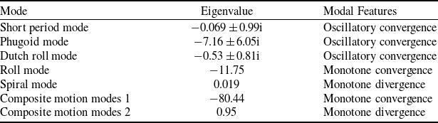
On the basis of equilibrium curve 1 and equilibrium curve 2 in Fig. 12, the multi-body dynamics model is linearised with the above theory. Firstly, the eigenvalues and eigenvectors of the two-body aircraft system matrix are calculated when the joint stiffness coefficient K=0, so as to analyse the stability of the free-hinged two-body aircraft. The analysis results of the main eigenvalues and eigenvectors of the free-hinged two-body aircraft are shown in Table 2.
Eigenvalue analysis of two-body aircraft

As can be seen from Table 2, due to the degree of freedom of relative motion of the two-body aircraft, in addition to the traditional flight mechanics modes that represent the overall rigid body motion characteristics, the two-body aircraft has a pair of composite motion modes that represent relative motion. One of the characteristic roots of the complex motion mode is a positive root and the other is a negative root. Thus, the equilibrium point is a saddle point. The convergent composite motion mode is dominated by the relative rolling motion of the two-body aircraft folding upwards relative to each other; the divergent composite motion mode is dominated by the relative rolling motion of a two-body aircraft folding downwards. The main reason is the torque generated by aerodynamic forces on the hinges, which causes the two-body aircraft to fold upwards relative to each other.
3.2.2 The stability of the equilibrium curve 1
Next, the paper will study the stability at the equilibrium point on equilibrium curve 1. The analysis of the stability of the equilibrium point on the equilibrium curve 1 is equivalent to the analysis of the change of the modal characteristic root of the two-body aircraft with the connection stiffness coefficient when the relative roll angle of the flight unit is equal to 0. The joint stiffness coefficient changes from 0 to 1000, and the characteristic root trajectories of rigid and composite motion modes of the two-body aircraft are shown in Figs. 13 and 14.
The variation of rigid-body motion modes with connection stiffness coefficients.

The influence of connection stiffness coefficient on composite motion modes.

From the variation of characteristic roots in Fig. 13, it can be seen that the connection stiffness coefficient does not affect the rigid motion mode of the multi-body aircraft. Because the moment generated by rotating elastic elements belongs to the internal forces of multi-body aircraft and does not affect the overall motion of the multi-body aircraft. From Fig. 14, it can be seen that the characteristic roots of the composite motion mode have changed from one positive root and one negative root to two negative roots, indicating that the connection stiffness coefficient between flight units has a stabilising effect on the composite motion mode of multi-body aircraft. Moreover, the larger the connection stiffness coefficient, the better the stabilising effect on the composite motion mode of multi-body aircraft. As the stiffness coefficient of the connection further increases, the characteristic roots of the composite motion mode move from the critical damping to the oscillating mode with two conjugate complex roots.
3.2.3 The stability of the equilibrium curve 2
After analysing the stability at the equilibrium point on the equilibrium curve 1, we will study the stability at the equilibrium point on the equilibrium curve 2. The equilibrium curve 2 corresponds to the steady glide of the two-body aircraft under different folding angles. By adjusting the joint stiffness coefficients, the two-body aircraft can achieve a stable glide at various folding angles. The roots and vectors of two-body aircraft under different folding angles are calculated by linearisation theory, so as to judge the stability of two-body aircraft under different folding angles. The folding angle of the two-body aircraft changes from 0rad to 1rad, and the root trajectory diagram is shown in Fig. 15.
Root locus diagram of feature roots. (a) Longitudinal modal characteristics root trace diagram. (b) Transverse and directional modal characteristics root trajectory diagram. (c) The composite motion mode 1 characteristic root trajectory diagram. (d) The composite motion mode 2 characteristic root trajectory diagram.

As can be seen from Fig. 15(c) and 15(d), with the change of folding angle of the two-body aircraft, the characteristic roots of the composite motion modes 1 and 2 move to the right along the real axis, and always maintain a negative real root and a positive real root. It can be seen that the equilibrium points on the equilibrium curve 2 are all dynamic unstable equilibrium points, and the main performance is that the compound motion mode is the saddle point.
3.2.3 Dynamic characteristics based on bifurcation analysis
Combined with the above dynamic stability analysis, the saddle-node bifurcation diagram shown in Fig. 16 can be obtained. In the figure, the solid line represents the dynamic stable equilibrium point, and the dashed line represents the dynamic unstable equilibrium point. The equilibrium point at the joint stiffness coefficient K = 0 is both saddle point and bifurcation point, and this bifurcation is saddle-node bifurcation. Equilibrium curve 2 divides the phase plane composed of joint stiffness coefficient and folding angle into stable region and unstable region. By analysing the stability in Fig. 16, it can be analysed that the two-body aircraft has the following dynamic characteristics during the collapse-delivery-development-glide process: (1) when the initial folding angle of the two-body aircraft is in the corresponding stable region as shown in Fig. 16, the two-body aircraft can deploy and slide steadily. When the initial folding angle of the two-body aircraft is too large, the two-body aircraft may not be able to deploy normally. (2) From balance curve 2, it can be seen that the smaller the stiffness coefficient of the connection, the smaller the folding angle corresponding to the dynamic unstable equilibrium point, and the larger the unstable region. It shows that the smaller the stiffness coefficient of the connection between the flight elements, the more unfavourable the stable deployment of the two-body aircraft. When the two-body aircraft accelerates to the critical speed under the influence of gravity, it fails to exhibit normal behaviour. Consequently, the flight state of the two-body aircraft will transition into an unstable region on equilibrium curve 2, leading to divergence in composite motion modes and preventing normal and stable development of the two-body aircraft.
The saddle-node bifurcation diagram.

3.3 Numerical results and performance analysis
In this section, numerical simulation is carried out based on the multi-body dynamics model. The effects of initial folding angle and joint stiffness coefficient on the dynamic characteristics of two-body aircraft during launch and unfold are analysed by the response curve. The simulation curve is integrated into the phase space diagram, and the influence of the stability region in Fig. 16 on the stable launch and unfold of the two-body aircraft is analysed. Where the response is calculated in the time domain, including the pitch angle response curve, roll angle response curve, and forward flight speed response curve.
3.3.1 The influence of initial folding angle on dynamic characteristics
The initial folding angles are 10 °, 20 °, and 30 °, respectively. Set the connection stiffness coefficient to 10 (N * m)/rad, initial velocity to 0.01m/s, initial pitch angle to -89.9 degrees, and thrust vector to 0N during the launching and unfolding process. Numerical simulation calculations were conducted under different initial folding angles to obtain the dynamic response curves of the two-body aircraft during the launching and unfolding process, as shown in Figs. 17–20.
Response curve of roll angle.

Response curve of pitch angle.

Response curve of forward flight speed.

Response curve of the angle-of-attack.

As can be seen from Fig. 17, when the initial folding angle is 30 degrees, the two-body aircraft begins to unfold under the action of spring recovery moment at the initial stage of launching. After about 2s, the two-body aircraft folds again under the action of aerodynamic force, which eventually causes the roll angle of each flight unit to diverge. When the initial folding angle is 20 degrees or 10 degrees, the rolling angle of each flight unit converges continuously under the action of the spring torque, and finally realises stable development. It can be seen that the smaller the initial folding angle is, the better the stable development of the two-body aircraft. As can be seen from the variation curve of the angle-of-attack in Fig. 20, the variation range of the angle-of-attack of each flight unit is not large and does not exceed the stall angle-of-attack during the launch and development of the two-body aircraft.
It can be seen from Figs. 18 and 19 that under the action of longitudinal stability, the pitch angle and forward flight speed of the two-body aircraft are constantly converging. After a period of movement, it eventually stabilises to the equilibrium point domain at equilibrium curve.
Figure 21 shows a schematic diagram of the first 6 seconds of the launching and unfolding process under three different initial folding angles. As can be seen from Fig. 21, when the initial folding angle is 30 degrees, the two-body aircraft will first unfold, but it will not fully unfold before the forward flight speed reaches the critical speed, and then the two-body aircraft will fold back again under the aerodynamic moment on the hinge. When the initial folding angle is 10 degrees and 20 degrees, respectively, the two-body aircraft enters the stable region before reaching the critical speed, so the stable deployment and transition to the stable long-period motion mode.
The launching and unfolding process under different initial folding angles.

By integrating the numerical simulation results into the phase diagram composed of folding angle and forward flight velocity, the manifold diagram shown in Fig. 22 can be obtained. When combined with the balance point on the equilibrium curve, it allows for a more intuitive analysis of the dynamic characteristics during launch and unfold.
Phase space diagram composed of forward flight velocity and folding angle.

As can be seen from Fig. 22, when the initial folding angle of the two-body aircraft is in the stable region, the two-body aircraft can unfold and slide steadily. When the two-body aircraft enters the stable area before the speed reaches the critical speed, it can also be stably unfolded. The equilibrium point 1 is the asymptotic stability point, and the two-body aircraft converges to the equilibrium point 1 under the action of its own stability. When the initial folding angle of the two-body aircraft is too large, the flight state cannot enter the stable area, which will cause the two-body aircraft to be unable to unfold normally, as shown by the dashed line in Fig. 22. This is consistent with conclusion 1.
3.3.2 The influence of connection stiffness coefficient on dynamic characteristics
The initial folding angle is 10 degrees, and the connection stiffness coefficients are set as 1(N * m)/rad, 10(N * m)/rad, 20(N * m)/rad, respectively. The initial velocity is 0.01m/s, the initial pitch angle is −89.9 degrees, and the thrust vector is 0 N during the launching and unfolding process. Numerical simulation calculations were conducted under different connection stiffness coefficient to obtain the dynamic response curves of the two-body aircraft during the launching and unfolding process, as shown in Figs. 23–26.
Response curve of roll angle.

Response curve of pitch angle.

Response curve of forward flight speed.

Response curve of the angle-of-attack.

As can be seen from Fig. 23, when the connection stiffness coefficient is 1(N * m)/rad, the two-body aircraft begins to deploy under the action of spring recovery torque at the early stage of launching. However, because the expansion rate is too slow, less than 1 second later, the two-body aircraft folds again under the action of aerodynamic force, which eventually leads to the divergence of the roll angle of each flight unit. When the connection stiffness coefficient is 10(N * m)/rad, the two-body aircraft completes the motion about 8 seconds after launching. When the connection stiffness coefficient is 20(N * m)/rad, the two-body aircraft completes the launch motion in 6 seconds after launching. It can be seen that the larger the connection stiffness coefficient, the faster the unfolding rate of the two-body aircraft, the more conducive to the stable unfolding of the two-body aircraft.
It can be seen from Figs. 24 and 25 that under the action of longitudinal stability, the pitch angle and forward flight speed of the two-body aircraft are constantly converging. After a period of movement, it eventually stabilises to the equilibrium point domain at equilibrium curve 1. Combined with Figs. 24 and 25, it can be seen that the launch and unfold motion of the two-body aircraft can be described as the high-frequency fast-unfolding motion and the low-frequency six-degree-of-freedom motion of the whole aircraft.
Figure 27 shows a schematic diagram of the first 6 seconds of the launching and unfolding process under three different connection stiffness coefficients. As can be seen from Fig. 27, when the connection stiffness coefficient is 1(N * m)/rad, the two-body aircraft is unfolded first. Due to the small spring connection stiffness coefficient, the expansion rate of the two-body aircraft is too slow, resulting in the forward flight speed reaching the critical speed before it is fully unfolded, and then the two-body aircraft folds back again under the aerodynamic moment on the hinge. When the stiffness coefficients of the connection are 10 (N * m)/rad and 20 (N * m)/rad, the two-body aircraft unfolds quickly and completes the deployment motion quickly. Therefore, it stably unfolds and transitions to a stable long-period motion mode.
Launching and unfolding process under different connection stiffness coefficients.

By integrating the numerical simulation results into the phase diagram composed of folding angle and forward flight velocity, a manifold diagram can be obtained as shown in Fig. 28. Combining the equilibrium points under different connection stiffness coefficients can provide a more intuitive analysis of the dynamic characteristics during the launching and unfolding process.
Phase space diagram composed of forward flight velocity and folding angle.

From Fig. 28, it can be seen that the larger the stiffness coefficient of the connection, the larger the dynamic stability region, which is more conducive to the stable deployment of the two-body aircraft and gradually converges to the stable state of equilibrium point 1. It can be clearly seen from the numerical simulation curve that the larger the connection stiffness coefficient, the faster the deployment rate of the two-body aircraft.
4.0 Two-body aircraft deployment experiment
Conduct deployment experiments on a two-body aircraft to investigate the correctness of the two inferences in Section 5.0 and the reliability of numerical simulations of multi-body dynamics models. The experimental aircraft adopts a normal layout, consisting of two wings, a single vertical tail, a flat tail and a fuselage. The main wing has a 1 m span and a 0.3 m chord with a cambered aerofoil (CLARK YS). The horizontal tail is 0.4 m in span with a 0.2 m chord. The vertical tail has a span of 0.2 m and a chord of 0.2 m. Both horizontal and vertical tails use symmetric aerofoils (NACA 0012) and are positioned 0.5 m from the centre of mass of the aircraft. The experimental principle aircraft and the delivery device are shown in Fig. 29.
The experimental aircraft and the delivery device.

The hinge mechanism, sensor and release mechanism are shown in Fig. 29. The axis of the hinged mechanism is parallel to the body axis of each flight unit during assembly, and the angle limit is added in the design of the hinged mechanism in order to prevent the flight unit from rolling excessively during the process of launching and developing. In addition, different number of springs are added into the groove of the hinge mechanism to control the joint stiffness coefficient of the two-body aircraft during the launching test. The sensor has a gyroscope and accelerometer to measure the quaternions of each flight unit in real time. The Euler angle of each flight unit and the folding angle between flight units can be obtained by solving. Install sensors at the centroids of each flight unit to detect real-time flight status information during the process of launching and developing. Three release mechanisms are used to suspend the two-body aircraft at three points, and the three points are simultaneously released through the ground remote control to achieve the purpose of deployment.
At the beginning of the deployment experiment, the initial height is about 15 meters, the initial pitch angle is 90 degrees, and the initial folding angle is 60 degrees. The deployment motion of a two-body aircraft in an open-loop state after deployment. The deployment process of the two-body aircraft is shown in Fig. 30. The attitude angles of each flight unit measured by the sensors and the calculated folding angles are shown in Figs. 31–32.
The launching and unfolding process of the two aircraft.

Experimental records of connected aircraft.

Experimental records of two-body aircraft (the process of launching and unfolding).

Comparison of experimental data and simulation calculations.

As can be seen from Fig. 30, it can be seen that the two-body aircraft began to unfold continuously under the action of spring recovery moment after launching. In the process of falling, in the role of its own stability, the two-body aircraft keeps pulling up, and finally flattening to achieve steady glide. Therefore, it is preliminarily verified that the folded two-body aircraft can realise the open-loop development movement after launching, and can actively pull up and finally transition to steady glide under the action of its own stability. However, due to the small stiffness coefficient and the large initial folding angle, the relative rolling motion modes of the two-body aircraft diverge when the speed accumulates to a certain extent. The final form of motion presented is the steady glide of the two-body aircraft as a whole, but the folding angle is increasing. Due to the existence of the limiting device, the two-body aircraft will maintain the shape of the maximum folding angle after folding to the maximum angle, until the stable landing.
The time constant in Fig. 31 is the time recorded by the sensor. As can be seen from the figure, the two-body aircraft began to release at 98 seconds, and the whole launching process maintained about 4 seconds. As can be seen from Fig. 32(b), the two-body aircraft keeps pulling up under the action of its own stability, so the pitch angle keeps increasing. From the perspective of the oscillation change of pitch angle, the two-body aircraft as a whole can sink and float, because the long-period mode of the two-body aircraft is stable, it can eventually converge to the equilibrium state. As can be seen from Fig. 32(d), the two-body aircraft was continuously deployed under the action of spring recovery torque in the first 1.8 seconds. When the sliding velocity reaches the critical velocity, it fails to unfold completely, and then under the action of aerodynamic force, the folding angle increases again, and finally diverges relative to the rolling motion mode. At approximately 102.5 seconds, the two-body aircraft touched down.
It can be seen from the time-varying data collected in the dropping experiment that when the connection stiffness is small or the initial folding angle is large, the two-body aircraft will first unfold, and when the speed reaches the critical point, the two-body aircraft will fold again under the action of aerodynamic force. This is consistent with the conclusion in Section 3.0. The correctness of the conclusion and the reliability of the numerical simulation of the multi-body dynamics model are verified.
As can be seen from the change curve of folding angle in Fig. 33, the change trend of folding angle calculated by numerical simulation of dynamics model is basically consistent with the change trend of experimental data of two-body aircraft launching and development. The maximum error of the folding angle amplitude is about 20%. The reliability of the calculation results of the dynamic model can be verified by comparing the numerical simulation with the experimental data.
5.0 Conclusions
In this paper, the absolute coordinate method and Lagrange multiplier method are used to establish the dynamics model of multi-body aircraft, and the crimped spring moment and damping moment models of flexible connection between flight units are added. The reference angle-of-attack, reference sideslip angle, relative attitude angle and relative attitude angular velocity of each flight unit are introduced as new variables, and the aerodynamic model of multi-body aircraft is established. Based on the force balance equation and moment balance equation, the equilibrium point of the multi-body aircraft is solved and the equilibrium curve of the two-body aircraft is obtained by taking the joint stiffness coefficient as the continuous variable parameter. The stability of the equilibrium point domain on the equilibrium curve with practical physical significance is analysed using linearisation theory. The dynamic characteristics of two-body aircraft during launch and development are analysed using bifurcation theory, and the stability region of initial folding angle and joint stiffness coefficient is determined. The effects of initial folding angle and joint stiffness coefficient on the dynamic characteristics and the reliability of stability region are analysed by numerical simulation. Finally, the effectiveness of the method in practical engineering application is proved by the experiment of two-body aircraft.
Through bifurcation branch analysis and numerical simulation calculation, the following conclusions can be drawn for airdrop folding two-body aircraft:
-
1) When the connection stiffness coefficient is 0, there is only one equilibrium point of the two-body aircraft, which is the saddle point. When the spring is added to the joint of the wing tip connecting multi-body aircraft, the balance point of the two-body aircraft is changed from one to two. Taking the joint stiffness coefficient as the continuous variable parameter, two equilibrium curves of the two-body aircraft are obtained. The equilibrium point on the equilibrium curve 1 corresponds to the steady glide flight of the two-body aircraft with the relative roll angle of 0 degree, which is the stable equilibrium point. The equilibrium point on the equilibrium curve 2 corresponds to the steady glide flight when the relative roll angle of the two-body aircraft is not equal to 0 degree, which is the unstable equilibrium point.
-
2) When the initial folding angle of the two-body aircraft is in the stable region, the two-body aircraft can be stably unfolded and stably slid. When the initial folding angle of the two-body aircraft is too large, the two-body aircraft may not be able to unfold normally.
-
3) For air-dropped folding two-body aircraft, the critical forward flight speed is the trim speed corresponding to the unstable equilibrium point. If the forward flight speed of the two-body aircraft reaches this critical speed and the folding angle does not enter the stable region, then it cannot be stably unfolded.
-
4) The smaller the stiffness coefficient is, the smaller the folding angle corresponding to the dynamic unstable equilibrium point is, and the larger the unstable region is. The main reason is that the smaller the connection stiffness coefficient between the flight units, the smaller the spring recovery moment, the more slower the deployment rate, the more unfavourable to the stable deployment of the two-body aircraft.