Introduction
Laser ablation is an effective and reliable technique for plasma formation and material modification due to small heat affected zone, controlled laser energy, non-contact nature, high precision, contamination free ablation process, and versatility (Liu et al., Reference Liu, Du and Mourou1997; Nolte et al., Reference Nolte, Momma, Jacobs, Tünnermann, Chichkov, Wellegehausen and Welling1997; Raheem and Abdurrahman, Reference Raheem and Abdurrahman2013; Saghebfar et al., Reference Saghebfar, Tehrani, Darbani and Majd2017; Lasemi et al., Reference Lasemi, Pacher, Zhigilei, Bomatí-Miguel, Lahoz and Kautek2018). Pulsed laser ablation of materials in the presence of ambient gas has extensive applications in different fields such as material processing, nanostructuring, industry, generation of nanoparticles, micromachining, laser-induced breakdown spectroscopy, and thin film deposition (Lippert et al., Reference Lippert, Stebani, Ihlemann, Nuyken and Wokaun1993; Krstulović et al., Reference Krstulović, Labazan, Milošević, Cvelbar, Vesel and Mozetič2006; Vikram et al., Reference Vikram, Wadadekar, Kembhavi and Vijayagovindan2010; Kalsoom et al., Reference Kalsoom, Bashir and Ali2013; Kumari and Khare, Reference Kumari and Khare2014; Mihailescu and Caricato, Reference Mihailescu and Caricato2018). In the process of laser ablation, the presence of ambient gas efficiently increases the ablation efficiency due to confinement effect, energy deposition of plasma ions, chemical reactivity of gases, and diffusion of ambient gases (Brosda et al., Reference Brosda, Castell-Munoz and Kunze1990; Chan and Hamilton, Reference Chan and Hamilton1998; Wu et al., Reference Wu, Wu, Zhang, Zhu, Ma and Zhigilei2018). Micro and nanostructuring of materials in the presence of various environmental gases has a vast range of applications in electronic, mechanical, fluidic, and optical devices (Duley, Reference Duley2006).
The sputtering yield measurement of laser ablated materials can be studied by using various techniques such as ion probes (Von Gutfeld and Dreyfus, Reference Von Gutfeld and Dreyfus1989), Faraday cups (Andersen and Bay, Reference Andersen and Bay1981), time of flight mass spectroscopy (Yar et al., Reference Yar, Ali and Baig2013), and Quartz Crystal Microbalance (QCM) (Hansen et al., Reference Hansen, Schou and Lunney1997). The QCM can be used to measure the amount of ablated material due to laser ablation and has various applications in surface sciences (Pérez and Weiner, Reference Pérez and Weiner1992). QCM works on the principle of piezoelectric effect which measures the mass in nanogram level and consists of a quartz crystal fixed between two electrodes (Pérez and Weiner, Reference Pérez and Weiner1992). The deposition of ablated material changes the resonance frequency of the quartz crystal which depends upon its mass, temperature, stress, and the exact position of the deposited material and is independent of the nature of material. By keeping all factors constant other than mass, the change in resonance frequency can be measured. The material deposited sensitivity of QCM is maximum in center and decreases as the radial distance from center is increased (Wajid, Reference Wajid1997).
Zirconium (Zr) has important applications in engineering and medical Physics (Sahasrabudhe and Bandyopadhyay, Reference Sahasrabudhe and Bandyopadhyay2018). Its good wear resistance, mechanical properties, corrosion resistance, thermal stability, minimum creep properties, and strong reactivity with oxygen at prominently high temperature makes it suitable for gas turbines, material crucibles, and motor tubes of rocket. It is also used in nuclear reactors for cladding of fuel rods because of its low neutron absorption cross-section. Investigation of the laser fluence effect on sputtering yield measurements and surface modification of Zr is significantly important (Ali et al., Reference Ali, Bashir, Rafique, Begum and Husinsky2017a, Reference Ali, Bashir, Rafique, Begum, Husinsky, Ajami and Natahala2017b; Hayat et al., Reference Hayat, Bashir, Strickland, Rafique, Wales, Tuairqi and Sanderson2019).
The present work is the continuation of sputtering yield measurements of metals by using QCM (Tehniat et al., Reference Tehniat, Bashir, Mahmood and Sharif2018). Tehniat et al. (Reference Tehniat, Bashir, Mahmood and Sharif2018) reported the laser ablation of Fe deposited on QCM at various fluences. The sputtering yield and surface structures are strongly dependent upon laser fluence, different environments and their pressures. Zhang et al. (Reference Zhang, Chu, Ho and Grigoropoulos1997) studied the laser ablation of thin gold film deposited on quartz crystal microbalance for different fluences and pressures under Ar gas. They studied that the ablation rate strongly depends on fluence and pressure. Cazzaniga et al. (Reference Cazzaniga, Ettlinger, Canulescu, Schou and Pryds2014) reported the laser ablation of metals (Ag, Cu, Sn, Zn) deposited on quartz crystal microbalance at a wavelength of 355 nm. They reported a strong dependence of deposition rate on fluence. Ursu et al. (Reference Ursu, Mihailescu, Nistor, Popa, Popescu, Teodorescu, Nanu, Prokhorov, Konov and Tokarev1985) reported the oxidizing and nitriding of Zr and Ti metals under oxygen and nitrogen environments. Hardness is increased due to the formation of oxides and nitrides. Ali et al. (Reference Ali, Bashir, Rafique, Begum, Husinsky, Ajami and Natahala2017b) studied the micro and nanostructuring of Zr in the presence of de-ionized water and propanol environments as a function of number of shots. Laser-induced periodic surface structures (LIPSS), pores, cavities, cracks, and cones-like structures are observed.
In this paper, the effect of fluence under constant pressure of two environments that is Ar and O2 on sputtering yield measurements and micro and nanostructuring of Zr metal has been investigated. Quartz crystal microbalance was employed to estimate the sputtering yield measurements. Different characterization techniques such as scanning electron microscope (SEM), optical microscope, UV-Visible spectroscopy, energy-dispersive X-ray spectroscopy (EDX), and micro hardness analyses have been employed to explore the surface morphology, crater depth, absorbance spectra, compositional analysis, and mechanical properties of laser ablated Zr respectively.
Experimental details
Zirconium is used as a target material with the purity of 99.999%. Squared shaped samples with a dimension of 2 cm × 2 cm × 0.3 cm were grinded, polished, and ultrasonically cleaned with acetone for 10 min. Prepared samples were positioned on the rotating target holder in a stainless steel vacuum chamber, which was evacuated to a base pressure of 10−3 mbar by using rotary pump.
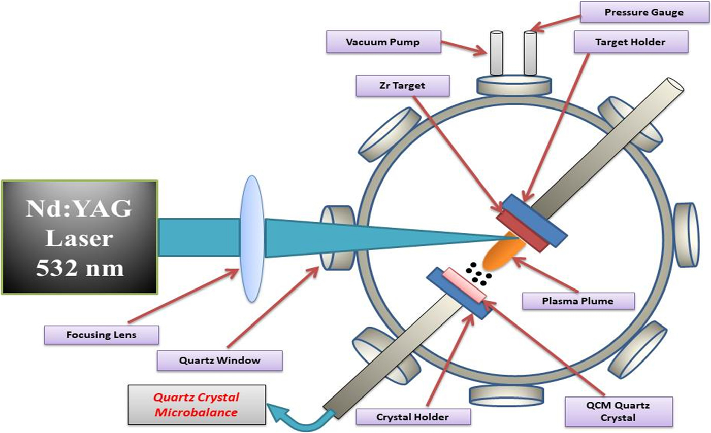
Q-switched Nd:YAG laser with second harmonic (Quantel 981C) of wavelength 532 nm, a pulse duration of 6 ns, and repetition rate of 10 Hz was employed for Zr target ablation. The targets were mounted on a continuously rotating sample stage with the help of motor. The fresh surface exposure was made to avoid crater formation and non-uniform pitting due to continuous laser pulses. A beam was focused on the target surface after passing through a lens of 50 cm focal length and hit at an angle of 45° with respect to target surface. The measured laser spot size was 0.003123 cm2. The QCM (QCM 200 Quartz Crystal Microbalance Digital Controller, SRS. Inc., Sunnyvale, California, USA) was used to measure the deposition rate. Figure 1 shows the schematic diagram of experimental setup. The quartz crystal oscillates at a frequency of 5 MHz with the help of oscillator and acts as a substrate placed parallel to target surface at a distance of 3 cm from target. Deposition on quartz crystal leads to a change in oscillation frequency. Two parts of the experiment were performed. The first part of the experiment was performed for sputtering yield measurements. Zr targets were exposed to 100 laser pulses at eight laser fluences of 16, 22.4, 28.8, 35.2, 41.6, 48, 54.4, 60.8 Jcm−2 corresponding to laser pulsed energies of 50, 70, 90, 110, 130, 150, 170, 190 mJ, respectively. To explore ambient gases effect all measurements were performed under two gases of Ar and O2 at a constant pressure of 10 Torr. The next part of the experiment was performed for SEM analysis for the same number of pulses, fluences, under the same environment at their corresponding constant pressure of 10 Torr.
The schematic diagram of experimental setup for the measurement of sputtering yield of laser ablated Zr.

SEM (JEOL JSM-6480 LV) was used to explore the surface morphology and EDX analysis of irradiated targets. Optical microscope (STM-6 Olympus) was used to measure the crater depth controlled by DPS-2 software. The UV-visible spectroscopy was employed to explore the oxide formation. The surface micro hardness analysis was performed by Vickers hardness tester (Zwick/Roell ZHU-5030).
Results and discussion
Sputtering yield measurements
To calculate the deposited mass on the quartz crystal the Sauerbrey equation is used (Sauerbrey, Reference Sauerbrey1959).
 $$\Delta f = -C_f\cdot \Delta {\rm m}$$
In the above relation, Δf is the change in frequency which is experimentally measured, C f is the sensitivity factor of quartz crystal and it is equal to 56.6 Hz μg−1cm2 and Δm is mass deposited on crystal.
The total ablation yield Y is measured from the deposited mass on quartz crystal placed at a distance of 3 cm parallel to target surface with angular distribution of cosnθ, as QCM is placed parallel to target surface so cosnθ = 1. (Svendsen et al., Reference Svendsen, Ellegaard and Schou1996)
 $$Y = 2{\rm \pi} r^2\mathop \int \limits_0^{{\rm \pi} /2} D\lpar {\rm \theta} \rpar \sin {\rm \theta} d{\rm \theta} \; $$
 $$ = 2{\rm \pi} r^2\displaystyle{{D\lpar {\rm \theta} \rpar } \over {n + 1}}$$
where D(θ) represents the area density of deposited mass on crystal and it is along the angle θ with respect to target surface normal. In the present study, the deposition rate is calculated in cm−2, where D(θ) is the mass deposited on QCM. The value of n = 3 is taken from Kool's analysis (Kools et al., Reference Kools, Van De Riet and Dieleman1993). According to this analysis the laser spot size area should be <1 mm for a single spot. In the present study the laser spot is 250 µm which is comparable to the value of Kool's analysis (Kools et al., Reference Kools, Van De Riet and Dieleman1993).
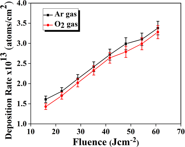
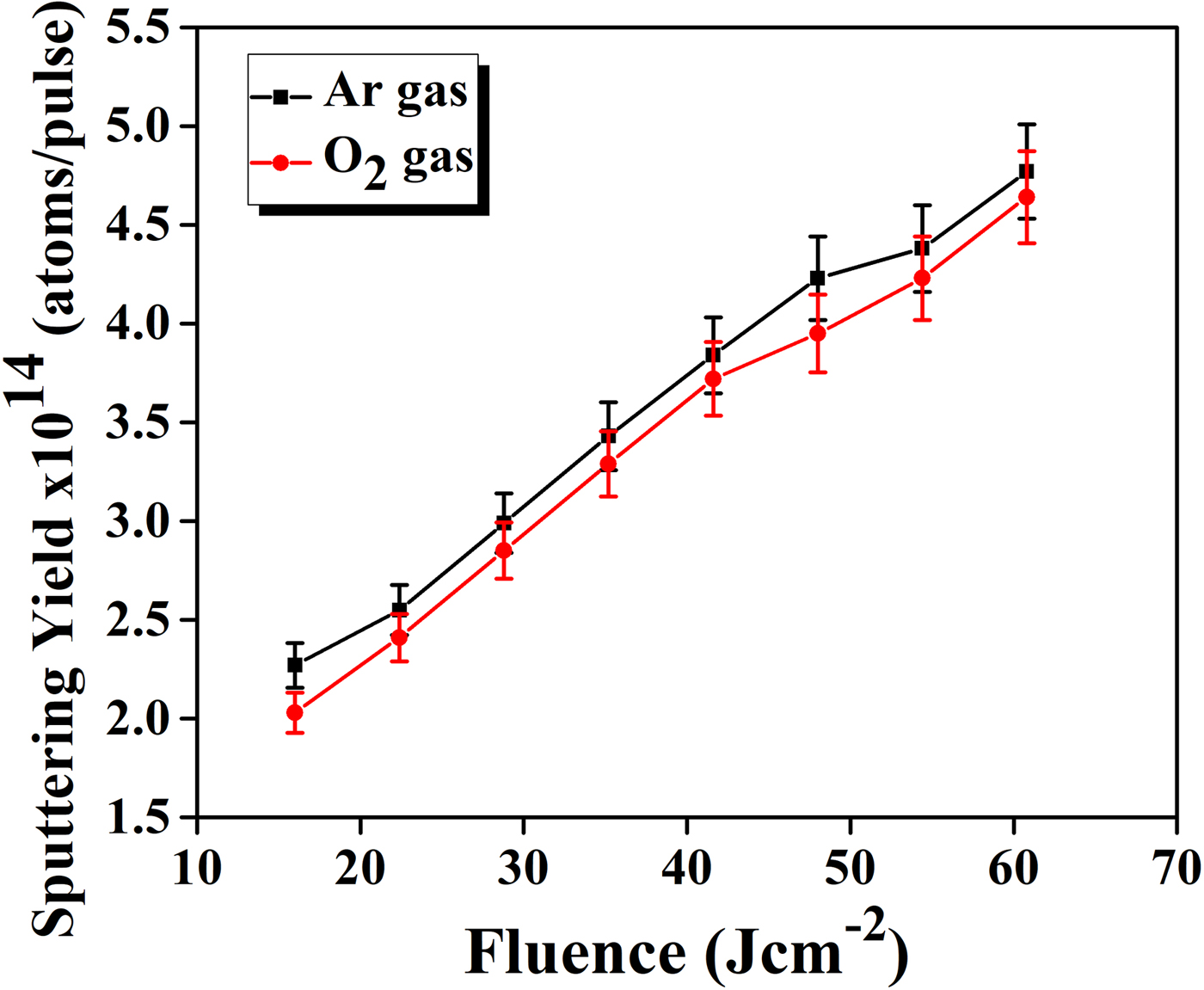
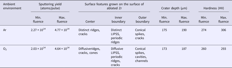
The dependence of deposition rate per pulse and sputtering yield per pulse on the laser fluences under two environments of Ar and O2 at constant pressure of 10 Torr are shown in graphs of Figures 2 and 3 respectively. These graphs show that the deposition rate and sputtering yield increase monotonically for all laser fluences under both environments. The deposition rate varies from 1.6 × 10¹³ to 3.38 × 10¹³ atoms/cm2 and 1.43 × 10¹³ to 3.28 × 10¹³ atoms/cm2, whereas, the sputtering yield varies from 2.27 × 10¹⁴ to 4.77 × 10¹⁴ atoms/pulse and from 2.03 × 10¹⁴ to 4.64 × 10¹⁴ atoms/pulse for Ar and O2 gases respectively. It is clearly seen from graphs of Figures 2 and 3 that the laser fluence is the controlling factor for the sputtering yield of Zr. Sputtering yield increases as the laser fluence increases irrespective of ambient conditions. However, both deposition rate and sputtering yield are higher in Ar as compared to O2.
The deposition rate of laser ablated Zr as a function of laser fluence ranging from 16 to 60.8 Jcm−2 under Ar and O2 environments measured by QCM.

The sputtering yield of laser ablated Zr as a function of laser fluence ranging from 16 to 60.8 Jcm−2 under Ar and O2 ambient environments measured by QCM.

Laser ablation of target metals results in heating, melting, and vaporization (Chichkov et al., Reference Chichkov, Momma, Nolte, Von Alvensleben and Tünnermann1996). Plasma plume is initiated when laser pulse interacts with the target material and heats the target surface to high temperature uptill tens of thousands Kelvin depending upon laser pulsed energy (Cristoforetti et al., Reference Cristoforetti, De Giacomo, Dell'Aglio, Legnaioli, Tognoni, Palleschi and Omenetto2010). The evolution of laser-induced plasma can be subdivided into three steps: Breakdown of target atoms, expansion, and confinement (Cristoforetti et al., Reference Cristoforetti, De Giacomo, Dell'Aglio, Legnaioli, Tognoni, Palleschi and Omenetto2010). In the present case the plasma evolution is only restricted to the first two steps. For laser ablation the laser fluence should be greater than the Zr threshold fluence. The threshold fluence of Zr is evaluated by the following relation (Cabalin and Laserna, Reference Cabalin and Laserna1998).
 $$F_{{\rm th}} = \rho L_v\sqrt {{\rm a}{\rm t}_{\rm e}} $$
where ρ is the density of Zr, L v represents the specific heat of vaporization per unit mass, a is the thermal diffusivity (K/ρC, where C is specific heat capacity and K is thermal conductivity), t e is the pulse duration of laser beam and their values are ρ = 6.52 gcm−3, L v = 6358 Jg−1, a = 0.127 cm2s−1, t e = 6 ns. By substituting these values, Zr threshold fluence comes out to be 1.14 Jcm−2. In present case laser fluence values are significantly higher than the Zr threshold fluence are able to cause ablation process.
Due to the interaction of the laser beam, the target material evaporates and ionizes and as a result the plasma plume is formed. In the start of laser–matter interaction, the plume is not affected by ambient gas properties and continues to expand freely (Cristoforetti et al., Reference Cristoforetti, Lorenzetti, Benedetti, Tognoni, Legnaioli and Palleschi2009). The expansion speed of plume is enhanced by continuous laser absorption into plume and produces a pile-up of vapor atoms at the vapor–ambient gas interface, called as snowplough effect, which generates shock waves (Cristoforetti et al., Reference Cristoforetti, Lorenzetti, Benedetti, Tognoni, Legnaioli and Palleschi2009). At the end of laser pulse, the plasma and shock wave are in contact and are able to ionize the ambient gas. As the shock wave weakens and plasma cools down during expansion, the shock-wave front and plasma detach at the times of order of hundreds of nanoseconds. The stopping radius of plasma is in mm (Cristoforetti et al., Reference Cristoforetti, Tognoni and Gizzi2013). The plasma expansion is considered isothermal, due to the interaction between laser beam and plasma species. The sputtering yield strongly depends upon the target material properties such as reflection, absorptivity, melting point, density, specific heat of vaporization, and work function (Iida, Reference Iida1990). As the fluence increases the laser energy deposition to the target material increases which results in enhancement of deposition rate and sputtering yield (graph of Figs 2 and 3).
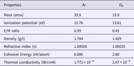
The deposition rate and sputtering yield are higher in case of Ar than O2 environment. The nature of environmental gases and their properties such as atomic mass, ionization potential, E/M ratio, cohesive energy, and thermal conductivity effect the plasma formation which in turn controls the sputtering yield of metallic Zr targets. Some important background gas properties are listed in Table 1. In the case of Ar the higher values of sputtering yield are due to the smaller E/M ratio, smaller thermal conductivity and higher atomic mass of Ar than O2 environment.
Some important physical properties of Ar and O2 environments

The background gas nature strongly influences the cascade growth of the electrons by absorption of laser pulse. The necessary condition for cascade-like growth is given by (George et al., Reference George, Kumar, Singh and Nampoori2010).
 $$\displaystyle{{{\rm d}{\rm {\it \epsilon}}} \over {{\rm d}t}} = \displaystyle{{4{\rm \pi} ^2e^2IV_{{\rm eff}}} \over {{\rm m}_{\rm e}{\rm c}{\rm \omega} ^2}}-\displaystyle{{2{\rm m}_{\rm e}V_{{\rm eff}}E} \over M}$$
where ε is the energy of the free electrons; e and m are the charge and the mass of an electron; M is the mass of the background gas neutral particles; E is the first ionization energy of the gas; V eff is the effective frequency of electron-neutral collision; I is the radiation intensity; and ω is the cyclic frequency of radiation.
The first term of equation expresses the rate of growth of energy by the absorption of laser photons. This part remains constant for all the gases. The second term represents the maximum rate of energy loss of the plasma due to elastic and inelastic collisions with neutral gas particles (Harilal et al., Reference Harilal, Bindhu, Nampoori and Vallabhan1998).
The E/M is the decisive factor for evaluating the energy loss in the cascade growth. The calculated value of E/M for Ar is 0.39 and for O2 is 0.43. This means that the cascade growth condition is more favorable for Ar as compared to O2 gas. Therefore , the Zr plasma formed in Ar gas is more absorptive than O2 gas, which is responsible for higher plasma parameters (electron temperature and electron number density) and correspondingly higher sputtering yield of Zr in Ar than O2.
The thermal conductivity of the background gas is also responsible for a higher sputtering yield of Zr in Ar than O2. The thermal conductivity (at 300 K) of Ar is 1.772 × 0−4 W/cmK which is smaller as compared to O2 which is 2.67 × 0−4 W/cmK. Therefore, the plasma in Ar environment cools slowly as compared to O2, thus resulting in high temperature of Zr plasma and correspondingly its high sputtering yield in the Ar atmosphere.
The rate of change of electron temperature in the plasma depends upon the sum of three terms viz., elastic collision, electron heating due to collisional excitation and de-excitation of metastable ions, and recombination of ions. The rate of loss of electron energy at short times is mainly influenced by the elastic collision term Q Δt and is given by (Khan et al., Reference Khan, Bashir, Hayat, Khaleeq-ur-Rahman and Haq2013).
 $$Q_{\Delta t} = \displaystyle{{2\,{\rm m}_{\rm e}} \over {M_{\rm B}}}{\rm \sigma} _{{\rm ea}}n_{\rm B}\left[ {\displaystyle{{5\,{\rm K}{\rm T}_{\rm e}} \over {{\rm \pi} {\rm m}_{\rm e}}}} \right]^{1/2}$$
where σea represents elastic scattering cross section between electrons and atoms; n B and M B are the density and mass of background gas atom; K is the Boltzmann constant; t e is the electron temperature; and m e is the mass of electron. Hence, the cooling process is inversely proportional to M B, so that the heavier gas is efficient for slow cooling of plasma. Therefore, the maximum value of plasma temperature is achieved for gas of maximum mass, that is Ar (Zehra et al., Reference Zehra, Bashir, Hassan, Ahmed, Akram and Hayat2017). It is concluded from the above results that laser-induced sputtering of materials is strongly influenced by the nature of background gas which in turn controls the micro/nanostructuring processes.
SEM analysis
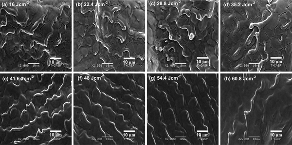
SEM images of Figures 4a–4h exhibit the surface morphology of centrally laser ablated areas of Zr under Ar environment at a pressure of 10 Torr for various fluences of (a) 16, (b) 22.4, (c) 28.8, (d) 35.2, (e) 41.6, (f) 48, (g) 54.4, and (h) 60.8 Jcm−2. For all laser fluences the distinct ridges, cones, and cracks are prominent features. Figure 4a represents Zr target surface at the lowest fluence of 16 Jcm−2 where the non-uniform melting, irregular ridges, and cracks are observed. Ridges are formed due to abrupt expulsion of molten material towards boundary by the recoil pressure of plasma (Ko et al., Reference Ko, Pan, Hwang, Chung, Ryu, Grigoropoulos and Poulikakos2007). During laser irradiation the loosely bound atoms of target react with gas particles and result the diffusion of gas particles into target that causes the non-equilibrium phase transformation processes. The transient melting, phase transformation, and rapid re-solidification are responsible for crack formation on the target surface (Khan et al., Reference Khan, Bashir, Hayat, Khaleeq-ur-Rahman and Haq2013). Another possible reason for crack formation can be thermal stresses that are generated by laser irradiation (Bashir et al., Reference Bashir, Vaheed and Mahmood2013). Increasing fluence from 16 to 22.4 Jcm−2, the ridges along with the conical protrusions and cracks are seen in Figure 4b. The coupling of laser irradiation to target surface and surface vaporization resistant impurities are basic cause for forward peaked cone evolution towards incoming laser irradiation (Kelly et al., Reference Kelly, Cuomo, Leary, Rothenberg, Braren and Aliotta1985; Sanchez et al., Reference Sanchez, Morenza, Aguiar, Delgado and Varela1996). For the fluence of 28.8 and 35.2 Jcm−2, the nonuniform ridges of conical protrusions and cracks are observed. The size of conical protrusions increases with increasing fluence. For fluence of 41.6 Jcm−2, the cracks and conical protrusions are vanished and extruded ridge-formation is seen. The elastic rebound of lattice during laser–matter interaction, incomplete melting of surface and the thermally expanded pushed away melted material from surface are responsible for such kind of features (Barmina et al., Reference Barmina, Barberoglu, Zorba, Simakin, Stratakis, Fotakis and Shafeev2009). The elevation of ridges decreases and regularity increases for the fluence values of 48 and 54.4 Jcm−2. This is attributed to the more laser energy deposition to the target surface and more melt flow towards boundary. For the highest fluence of 60.8 Jcm−2, the diffusive ridges are seen only in the central area. The density of ridges decreases due to their destruction which is attributed to more coupling of energy to target surface.
SEM images exhibiting the surface morphology of central area of laser ablated Zr under Ar environment at 10 Torr pressure for different laser fluences of (a) 16 Jcm−2, (b) 22.4 Jcm−2, (c) 28.8 Jcm−2, (d) 35.2 Jcm−2, (e) 41.6 Jcm−2, (f) 48 Jcm−2, (g) 54.4 Jcm−2, and (h) 60.8 Jcm−2.

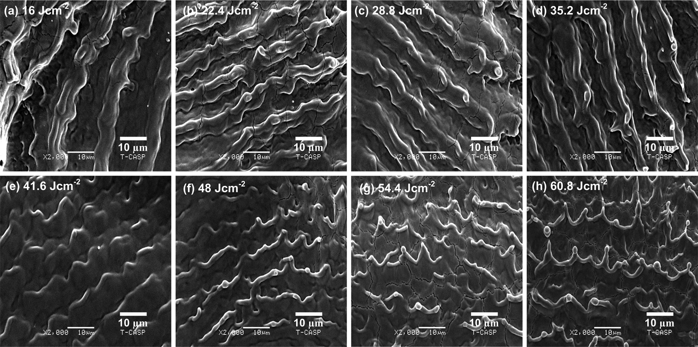
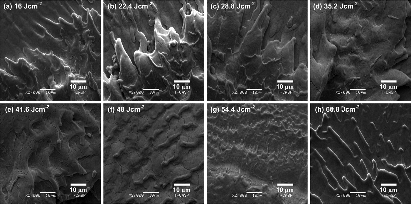
SEM images of Figures 5a–5h exhibit the modified inner boundaries of the laser ablated areas of Zr-metal under Ar environment at a pressure of 10 Torr for various fluences of (a) 16, (b) 22.4, (c) 28.8, (d) 35.2, (e) 41.6, (f) 48, (g) 54.4, and (h) 60.8 Jcm−2. LIPSS, periodic ridges, cracks, and cones are dominant characteristics for all laser fluences. The periodicity of periodic surface structures also called ripples is decreased from 16 to 12.5 µm as the fluence increases from 16 to 22.4 Jcm−2, respectively. From Figures 5b–5d, the periodicity of ripples decreases from 12.5 to 11.5 µm. Figures 5b–5d reveal that the regularity and smoothness of micro-sized ripples are significantly higher for fluences of 22.4, 28.8, and 35.2 Jcm−2 than other fluences. Another feature between the ripples is the remnants of turbulent melt flow. The cracking is also seen. By increasing further fluence up to 41.6 Jcm−2, the ripples are transformed into periodic ridges. In Figure 5f the periodic ridges with cones and droplets at their tops are observed for the fluence of 48 Jcm−2. From Figures 5e–5g, the periodicity of periodic ridges decreases from 11 to 9.5 µm. The evaporation of resistive impurities by preferential ablation, re-deposition of ablated material and hydrodynamic sputtering is considered for cone formation (Kalsoom et al., Reference Kalsoom, Bashir and Ali2013). By increasing the fluence up to 54.4 Jcm−2, the periodic ridge formation with cones, droplets at their heads is pronounced and crack formation is seen in Figure 5g. For the highest fluence of 60.8 Jcm−2, both the sharpness and height of cones are increased as shown in Figure 5h. The periodicity of periodic ridges increases from 9.5 to 11 µm as the fluence is increased from 54.4 to 60.8 Jcm−2.
SEM images exhibiting the surface morphology of inner boundary of laser ablated Zr under Ar environment at 10 Torr pressure for different laser fluences of (a) 16 Jcm−2, (b) 22.4 Jcm−2, (c) 28.8 Jcm−2, (d) 35.2 Jcm−2, (e) 41.6 Jcm−2, (f) 48 Jcm−2, (g) 54.4 Jcm−2, and (h) 60.8 Jcm−2.

The formation mechanism of ripples can be described by several theories such as generation of Surface Plasmon Polariton (SPP) (Garrelie et al., Reference Garrelie, Colombier, Pigeon, Tonchev, Faure, Bounhalli, Reynaud and Parriaux2011; Das et al., Reference Das, Khan, Parandhaman, Laffir, Guha, Sekaran and Mandal2013), interference model (Sipe et al., Reference Sipe, Young, Preston and Van Driel1983), Kelvin-Helmholtz instability (Ang et al., Reference Ang, Lau, Gilgenbach, Spindler, Lash and Kovaleski1998; Liu et al., Reference Liu, Jiang, Yang, Guan and Dai2011) and capillary waves (Shen et al., Reference Shen, Crouch, Carey, Younkin, Mazur, Sheehy and Friend2003). In laser–matter interaction process, the surface plasmons are generated by coupling of electric part of laser pulse to target surface which would stimulate oscillation in forefront of the target surface. The surface plasmons are produced during laser–matter interaction, when electric part of laser excites oscillations in forefront of target surface. The laser irradiation is dispersed normal to surface from generated surface defects and standing wave patterns arise. Plasma oscillations driven by combined electric field distribution of incident, reflected and diffracted waves result in the erosion and expulsion of material to form valleys and as a result the ripples are formed. The following relation is used to calculate the periodicity of ripples by SPP (Albu et al., Reference Albu, Dinescu, Filipescu, Ulmeanu and Zamfirescu2013).
 $${\rm \lambda} _{{\rm SP}} = {\rm \lambda} _0R_{\rm e}\left[ {{\left( {\displaystyle{{{\rm \varepsilon}_{\rm d} + {\rm \varepsilon}_{\rm m}} \over {{\rm \varepsilon}_{\rm d}{\rm \varepsilon}_{\rm m}}}} \right)}^{1/2}} \right]$$
where λSP represents the periodicity of LIPSS, λ0 is the laser beam wavelength, εd is the permittivity of dielectric medium and εm = εr + iεi refers to the complex dielectric constant of material. The periodicity of ripples by using the above relation comes out to be in the range of hundreds of nm (Albu et al., Reference Albu, Dinescu, Filipescu, Ulmeanu and Zamfirescu2013). The experimentally measured values of periodicity are significantly higher than this range (9–16 µm). Thus, the theory of SSP is not applicable in our case.
The ripples evolution is explainable by the interference between the incident laser light with “Surface Electromagnetic Waves” (Sipe et al., Reference Sipe, Young, Preston and Van Driel1983). For all fluences the incident laser light wavelength (0.532 µm) differs from the average periodicity of ripples (9.5–16 µm). This indicates that the interference effects are eliminated for ripple formation. The generation of hydrodynamic instabilities called Kelvin-Helmholtz instability is considered as the most probable cause for ripple formation (Liu et al., Reference Liu, Jiang, Yang, Guan and Dai2011). During laser–matter interaction, the molten surface of Zr is considered as fluid and high-pressure plasma plume behaves as a source of wind. The micro-sized ripples are generated, when the laser-induced surface waves are produced and after melting, these frozen structures are permanently imprinted in the form of LIPSS on the material surface (Ang et al., Reference Ang, Lau, Gilgenbach, Spindler, Lash and Kovaleski1998; Liu et al., Reference Liu, Jiang, Yang, Guan and Dai2011).
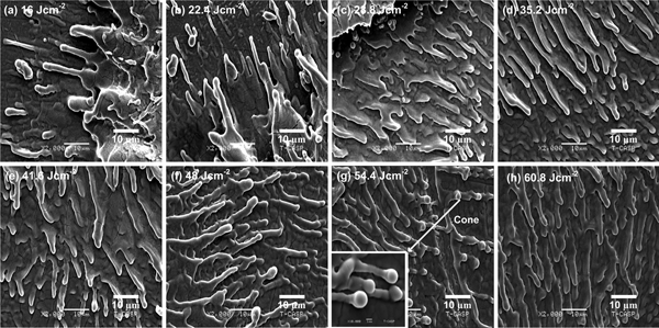
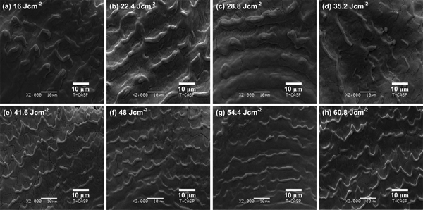
The SEM images of Figures 6a–6h reveal the outer boundaries of the laser ablated areas of Zr-metal under Ar environment at a pressure of 10 Torr for various fluences of (a) 16, (b) 22.4, (c) 28.8, (d) 35.2, (e) 41.6, (f) 48, (g) 54.4, and (h) 60.8 Jcm−2. For all fluences the spikes and cones are prominent features. Figure 6a represents non-uniform micro-sized spikes and droplets at the fluence of 16 Jcm−2. The spikes growth arises in two stages. In the first stage, incoming laser irradiation exerts pressure on target surface and the surface depressions as well as stresses are generated. In the second stage, when the laser pulse is over, relaxation of thermal stresses originate the formation of spikes (Mansour et al., Reference Mansour, Jamshidi-Ghaleh and Ashkenasi2006). In Figure 6b, on the top of some spikes, the tiny globules or round caps are seen at the fluence of 22.4 Jcm−2. The density of spikes increases and their size decreases. Non-uniform cones are observed in Figure 6c at the fluence of 28.8 Jcm−2. The growth of cones occurs in three steps: In the first step, before the material processing the generation of precursor sites, that is micro/nano scale laser-induced surface roughness and defects are generated. In the second step, the incident laser light scatters from these sites. The increased preferential absorption of fluence as well as enhanced ablation rate in these sites between the valleys finally evolves into cones. The growth and merging of conical structures occur in the third step (Bashir et al., Reference Bashir, Khurshid, Akram, Ali, Ahmad and Yousaf2015a). At a fluence of 35.2 Jcm−2, sharp and non-uniform cones are identified in Figure 6d. For the fluences of 41.6 and 48 Jcm−2, the sharp cones transform into wider based cones. The uniformity, size of globules, and their size are increased with increasing fluence. The inset of Figure 6g shows the magnified view of cluster of cones. The diameter of globules ranges 1–2 µm. For the highest fluence of 60.8 Jcm−2, the diffusive cones with uniform distribution are seen in Figure 6h. The increase in uniformity is attributed to more energy deposition to target surface.
SEM images exhibiting the surface morphology of outer boundary of laser ablated Zr under Ar environment at 10 Torr pressure for different laser fluences of (a) 16 Jcm−2, (b) 22.4 Jcm−2, (c) 28.8 Jcm−2, (d) 35.2 Jcm−2, (e) 41.6 Jcm−2, (f) 48 Jcm−2, (g) 54.4 Jcm−2, and (h) 60.8 Jcm−2.

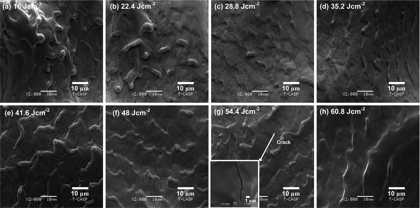
SEM micrographs of Figures 7a–7h show the centrally laser ablated areas of Zr-metal under O2 environment at a pressure of 10 Torr for various fluences of (a) 16, (b) 22.4, (c) 28.8, (d) 35.2, (e) 41.6, (f) 48, (g) 54.4, and (h) 60.8 Jcm−2. The dominant features for all the fluences are diffusive ridges, cracks, and cones. The appearance of structures is similar as has been observed under Ar environment. However, all the structures are diffusive under O2 environment as compared to Ar. For the fluence of 16 and 22.4 Jcm−2, the non-uniform melting of material and diffusive cones are observed. In Figure 7c, for the fluence of 28.8 Jcm−2 the diffusive ridges are observed. For the fluence of 35.2 and 41.6 Jcm−2, the distinctness and elevation of ridges are increased. Some ridges have the spherical top heads and wide bases. Further enhancement in fluence up to 48 Jcm−2, the ridges and cracks become diffusive. The elevation of ridges decreases. For the fluence of 54.4 Jcm−2, the ridges become more regular. Inset of Figure 5g shows the magnified view of crack formation with <1 µm width. For the highest fluence of 60.8 Jcm−2, the diffusive ridges are observed and cracks are completely vanished in Figure 7h.
SEM images exhibiting the surface morphology of central area of laser ablated Zr under O2 background environment at 10 Torr pressure for different laser fluences of (a) 16 Jcm−2, (b) 22.4 Jcm−2, (c) 28.8 Jcm−2, (d) 35.2 Jcm−2, (e) 41.6 Jcm−2, (f) 48 Jcm−2, (g) 54.4 Jcm−2, and (h) 60.8 Jcm−2.

SEM micrographs of Figures 8a–8h exhibit the inner boundaries of the laser ablated areas of Zr under O2 environment at a pressure of 10 Torr for various fluences of (a) 16, (b) 22.4, (c) 28.8, (d) 35.2, (e) 41.6, (f) 48, (g) 54.4, and (h) 60.8 Jcm−2. Ripples, cracks, and ridges are characteristic features for all fluences. For the lowest fluence of 16 Jcm−2, the non-uniform melting of material is observed. The diffusive ripples transform into distinct structures and their periodicity decreases from 13.5 µm to 13 µm when the fluence is increased from 22.4 to 28.8 Jcm−2 (Figs 8b and 8c). The remnant of turbulent melt flow is another feature between the ripples in Figure 8b. By increasing the fluence from 22.8 to 35.2 Jcm−2, both the distinctness and periodicity of ripples decreases from 13 to 12.5 µm. For the fluence of 41.6 Jcm−2, the sharp periodic ridges are observed in Figure 8e. The head or cap on the top of periodic ridges is also observed. In Figures 8e–8g, the elevation and smoothness of periodic ridges increases whereas, their periodicity decreases from 12 to 10 µm. Further enhancement in fluence upto 60.8 Jcm−2, leads to an increase in both the sharpness and periodicity from 10 to 11 µm of periodic ridges.
SEM images exhibiting the surface morphology of inner boundary of laser ablated Zr under O2background environment at 10 Torr pressure for different laser fluences of (a) 16 Jcm−2, (b) 22.4 Jcm−2, (c) 28.8 Jcm−2, (d) 35.2 Jcm−2, (e) 41.6 Jcm−2, (f) 48 Jcm−2, (g) 54.4 Jcm−2, and (h) 60.8 Jcm−2.

SEM micrographs of Figures 9a–9h reveal the outer boundaries of the laser ablated areas of Zr-metal under O2 environment at a pressure of 10 Torr for various fluences of (a) 16, (b) 22.4, (c) 28.8, (d) 35.2, (e) 41.6, (f) 48, (g) 54.4, and (h) 60.8 Jcm−2. Spikes, ripples, cavities, and channels are dominant features for all fluences. For the lowest fluence of 16 Jcm−2, the micro-sized spikes are observed. Figures 9b–9c exhibit that the size of spikes increases and their density decreases for the fluence 22.4 and 28.8 Jcm−2 respectively. The non-uniform melting and diffusive cavities are observed in Figure 9d which turns into distinct cavities in Figure 9e. Cavity formation is explainable on the basis of heating of subsurface layer and rapid volume expansion in the target surface (Lappalainen et al., Reference Lappalainen, Frantti and Lantto1998). The recoil pressure of plasma enhances deposited pressure on the target and molten material is expelled out explosively from the target surface that may also be accounted for the cavity formation (Körner et al., Reference Körner, Mayerhofer, Hartmann and Bergmann1996). By increasing the fluence, distinctness of cavities increases as more energy is transferred to lattice. The width of cracks increases as fluence increases from 41.6 to 48 Jcm−2. Figure 9f depicts the formation of ripples at 48 Jcm−2 and they are vanished as the fluence increases to the 54.4 Jcm−2. In Figure 9g, the cone formation is observed with the occurrence of splashed surface. For the highest fluence the non-uniform spikes and channels are observed in Figure 9h.
SEM images exhibiting the surface morphology of outer boundary of laser ablated Zr under O2background environment at 10 Torr pressure for different laser fluences of (a) 16 Jcm−2, (b) 22.4 Jcm−2, (c) 28.8 Jcm−2, (d) 35.2 Jcm−2, (e) 41.6 Jcm−2, (f) 48 Jcm−2, (g) 54.4 Jcm−2, and (h) 60.8 Jcm−2.

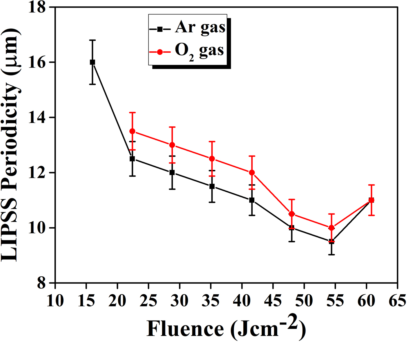
The graph of Figure 10 shows the periodicity of LIPSS as a function of laser fluence in Ar and O2 environments for laser ablated Zr. For both environments, the periodicity decreases with increasing fluence. However, for the highest fluence 60.8 Jcm−2, LIPSS formation is completely unorganized and broken, and their periodicity increases slightly. It is observed that periodicity of LIPSS on Zr in case of its ablation in Ar is smaller than O2 environment. It employs that not only the material and laser fluence but also the complicated energy-coupling phenomenon from the background gases also play a significant role in the growth of fine ripples. By increasing fluence the more laser energy deposition results into the rise of surface temperature. The rise of surface temperature generates the shear force due to surface tension gradient, which is responsible for the movement of hot regions to cold regions to minimize surface deformation and its energy. These effects may be accounted for the change in periodicity of LIPSS (Bashir et al., Reference Bashir, Rafique, Nathala, Ajami and Husinsky2015b). The decrease in the periodicity of LIPSS by increasing fluence is attributed to the extensive melting of material, resolidification due to thermal effects which result in merging of LIPSS (Iqbal et al., Reference Iqbal, Bashir, Rafique, Dawood, Akram, Mahmood, Hayat, Ahmad, Hussain and Mahmood2015).
The variation in LIPSS periodicity on Zr surface due to laser ablation for various fluences ranging from 16 to 60.8 Jcm 2 under Ar and O2 environments at constant pressure 10 Torr.

The surface morphology has strong correlation with sputtering yield of Zr after ablation in background gases of Ar and O2. In the case of Ar the higher values of sputtering yield are achieved along with the growth of well-defined and distinct surface features. This is explainable on the basis of properties of environmental gases such as E/M ratio, thermal conductivity and ionization potential (see Table 1). In the case of Ar, the choice of lower value of E/M ratio (0.39) corresponds to favorable cascade growth which is responsible of well distinct features and higher sputtering yield values as compared to O2 (0.43) gas. The lower value of thermal conductivity (1.772 × 10⁻⁴ W/cmK) and atomic mass (39.9 amu) of Ar than O2 (2.67 × 10⁻⁴ W/cmK), (15.9 amu) correspond to less heat dissipation and slow cooling of Zr plasma in Ar than O2. Also the K.E energy losses are less significant in the case of Ar than O2 (Dawood et al., Reference Dawood, Bashir, Akram, Hayat, Ahmed, Iqbal and Kazmi2015). The higher values of sputtering yield correspond to distinct features of laser ablated Zr.
Crater depth analysis
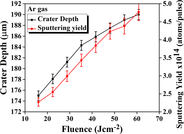
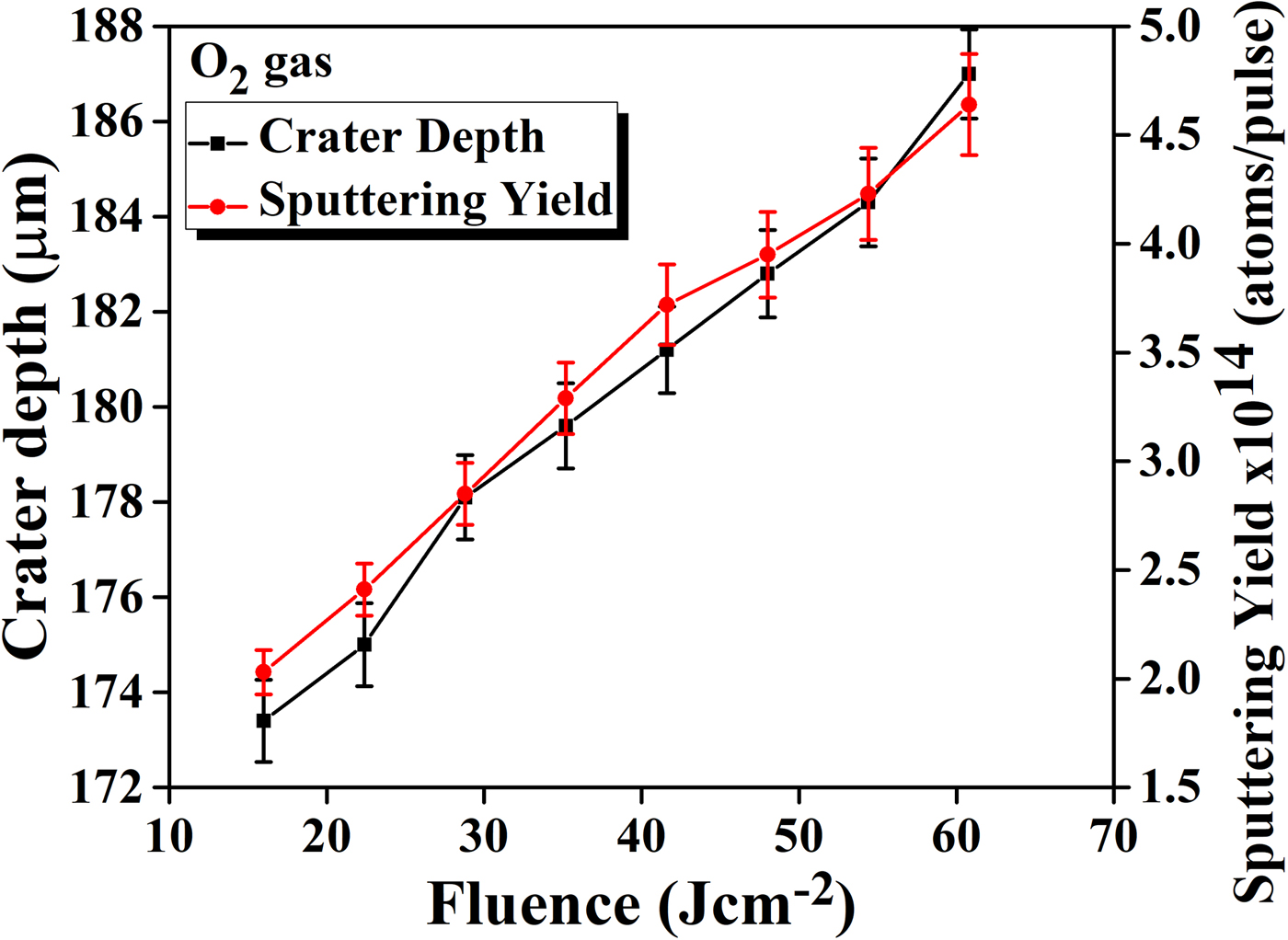
The graphs of Figures 11 and 12 show the relationship between measured crater depth and sputtering yield of laser ablated Zr as a function of laser fluence in Ar and O2 environments at 10 Torr pressure respectively. For both environments the crater depth shows the monotonically increasing trend. For all fluences, the crater depth is in μm range. The measured value of crater depth in case of Ar varies from 175 to 190 µm and in O2 it varies from 173 to 187 µm. The higher crater depths of Zr measured in Ar gas are exactly in accordance with sputtering yield values.
The comparison of crater depth and sputtering yield of laser ablated Zr as a function of laser fluence under Ar environment at 10 Torr pressure.

The comparison of crater depth and sputtering yield of laser ablated Zr as a function of laser fluence under O2background environment at 10 Torr pressure.

The influence of environmental gases is also pronounced on crater depth analysis. The increasing trend of crater depth with increasing fluence is explained on the basis of more energy deposition which results in enhanced mass removal of Zr target (Zehra et al., Reference Zehra, Bashir, Hassan, Hayat and Akram2018). The lower crater depth values in case of O2 gas are attributed to utilization of laser energy in different mechanisms such as chemical reactions occurring among reactive species and dissociation of gas molecules (Bogaerts et al., Reference Bogaerts, Chen and Bleiner2006).The observed crater depths for both environments are exactly in accordance with the sputtering yield results obtained from QCM. Therefore, the suitable combination of laser fluence and background gases can optimize the surface structuring and micromachining of Zr target.
EDX analysis
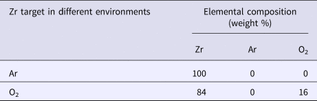
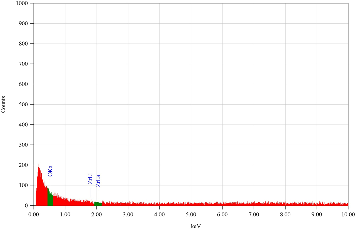
Table 2 represents the EDX analysis of the laser irradiated Zr target under Ar and O2 environments at a constant pressure of 10 Torr for compositional analysis at a fluence of 16 Jcm−2. The presence of oxygen is attributed to the oxide formation of Zr due to laser irradiation in O2 environment as shown in Figure 13.
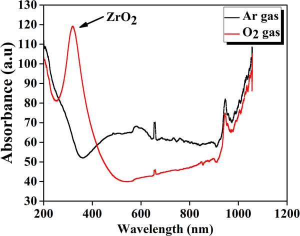
UV visible absorbance spectra of laser ablated Zr at a fluence of 16 Jcm−2 under Ar and O2 environments.

Energy-dispersive X-ray spectroscopy (EDX) analysis of laser irradiated Zr targets for the fluence of 16 Jcm−2 at 10 Torr pressure of Ar and O2 environments

UV-visible spectroscopy
The effect of ambient environments on the absorbance of laser ablated Zr is shown in graph of Figure 14. The lowest fluence of 16 Jcm−2 is selected for optical absorption spectra. The irradiated Zr target is more absorptive in visible region as compared to UV region. In UV region no band is formed in the case of Ar gas, whereas a broad band is formed in the case of O2 gas at 320 nm due to the formation of ZrO2. Zhang et al. (Zhang and Lin, Reference Zhang and Lin2011) reported the peak formation of ZrO2 at 320 nm in absorption spectra which is similar to the peak observed in the present case. The oxide formation in O2 gas influences the surface morphology and makes the surface features diffusive and also reduces the crater depth as compared to Ar gas.
The energy-dispersive X-ray graph exhibiting the percentage composition of laser irradiated Zr target at laser fluence of 16 Jcm−2 under 10 Torr pressure in O2.

Micro hardness
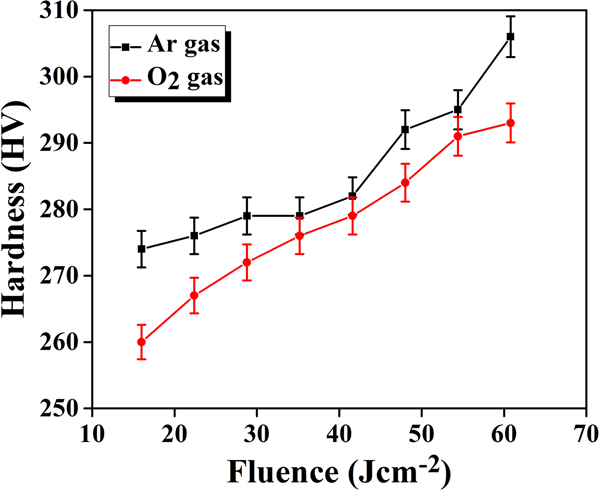
The graph of Figure 15 depicts the change in micro hardness of laser ablated Zr at 10 Torr pressure under two ambient environments of Ar and O2 for various fluences ranging from 16 to 60.8 Jcm−2. It is observed that the micro hardness monotonically increases as the laser fluence increases under both environments. For different laser fluences the micro hardness values vary from 274–306 HV and 260–293 HV under Ar and O2 respectively. It is clear from Figure 15 that the micro hardness of laser ablated Zr is higher in case of Ar than O2 environment. The increasing trend in micro hardness is attributed to lattice disorder. Due to laser induced heating, the thermal compressive stresses and changes in crystal structure are produced in material that are responsible for increasing micro hardness (Hull and Bacon, Reference Hull and Bacon2011). Another possible reason for increase in hardness is more diffusion of O2 atoms into the material by increasing the fluence. Many factors are responsible for the increase in hardness such as lattice defects, phase composition, oxide formation and crystal structure (Warcholinski and Gilewicz, Reference Warcholinski and Gilewicz2009).These micro hardness results are well correlated with sputtering yield, SEM and crater depth analyses. In the case of Ar the higher values of sputtering yield and crater depth are achieved, and similarly the distinct and well-defined surface features are observed which lead to higher values of hardness as shown in Table 3.
The micro hardness analysis of laser ablated Zr for different fluences under Ar and O2 background gases at constant pressure 10 Torr.

Summary describing the effect of laser fluence and environmental gases on sputtering yield measurements, surface modifications, crater depth, and hardness of laser irradiated Zr

Conclusions
The significant effects of laser fluence and nature of ambient environment on the sputtering yield measurements, surface morphology, crater depth analysis, UV-visible spectroscopy, EDX analysis, and micro hardness of Zr has been revealed. It was found that the sputtering yield was strongly dependent upon laser fluence and nature of ambient environment. The sputtering yield increased monotonically with increasing fluence and attained its maxima at the maximum fluence under both environments. However, its values are higher in Ar than O2 for all fluences. SEM investigations reveal the formation of different surface features such as ridges, cones, and cracks on central areas, whereas; LIPSS, periodic ridges, and cones were observed at inner boundaries and also the spikes, cavities, and channels were observed at outer boundaries of laser ablated Zr under both environments (Ar and O2). The distinct surface features were observed in the case of Ar than O2 environment and were found to be strongly dependent upon fluence and nature of environment. The crater depth revealed the monotonically increasing trend with increasing fluence under both environments and strong dependence upon fluence and ambient environment. The EDX analysis revealed the oxide formation and percentage increase in O2 content for laser irradiated Zr in O2 environment. UV-visible Spectroscopy showed that the visible light is more absorptive than UV light and ZrO2 is formed at 320 nm. The hardness of Zr was found to be increased after laser irradiation and showed an increasing trend with increasing fluence. In the case of Ar, the higher values of sputtering yield, crater depth, and micro-hardness were observed and are well correlated with distinct surface features in Ar than O2 environment.