





1. Introduction
Autophoretic motion comprises the propulsion of particles due to self-generated gradients (Anderson Reference Anderson1989; Paxton et al. Reference Paxton, Sundararajan, Mallouk and Sen2006; Ebbens & Howse Reference Ebbens and Howse2010; Moran & Posner Reference Moran and Posner2017), typically on an energy scale comparable to that of thermal fluctuations (Batchelor Reference Batchelor1976; Graham Reference Graham2018). This self-propulsion mechanism allows systems of phoretic particles to mimic the locomotion of microorganisms (Brennen & Winet Reference Brennen and Winet1977; Goldstein Reference Goldstein2015), making them useful in the study of the fundamental principles of motility and collective behaviour (Palacci et al. Reference Palacci, Sacanna, Steinberg, Pine and Chaikin2013; Illien, Golestanian & Sen Reference Illien, Golestanian and Sen2017; Shaebani et al. Reference Shaebani, Wysocki, Winkler, Gompper and Rieger2020; Zöttl & Stark Reference Zöttl and Stark2023; Kumar et al. Reference Kumar, Murali, Subramaniam, Singh and Thutupalli2024). In particular, the study of interactions of autophoretic particles with nearby boundaries is relevant in micro-fluidics, biophysics and surface science (Kreuter et al. Reference Kreuter, Siems, Nielaba, Leiderer and Erbe2013; Ibrahim & Liverpool Reference Ibrahim and Liverpool2015; Uspal et al. Reference Uspal, Popescu, Dietrich and Tasinkevych2015; Shen, Würger & Lintuvuori Reference Shen, Würger and Lintuvuori2018; Thutupalli et al. Reference Thutupalli, Geyer, Singh, Adhikari and Stone2018; Singh, Adhikari & Cates Reference Singh, Adhikari and Cates2019).
Our goal is thus to formulate an effective description in which Brownian motion and autophoresis of active particles can be studied when suspended in a complex environment. Models for self-diffusiophoresis typically assume that chemical gradients generated by the particle induce an osmotic pressure, which is balanced by viscous stresses driving an effective slip flow confined to a thin layer at the surface of the particle (Anderson, Lowell & Prieve Reference Anderson, Lowell and Prieve1982). This sets the surrounding fluid in motion, with fluid stresses reacting back on the particle and setting it in motion. To compute the particle dynamics usually requires solving for the concentration field and the fluid flow in the bulk, and subsequently obtaining the stresses on the particle by matching all relevant boundary conditions (Golestanian, Liverpool & Ajdari Reference Golestanian, Liverpool and Ajdari2005, Reference Golestanian, Liverpool and Ajdari2007). Instead, by using a boundary-domain integral approach, we directly obtain the concentration distribution and the resulting traction (force per unit area) on the surface of the particle, obviating the need for solving the governing equations in the bulk. Compared with more conventional kinematic approaches (Lighthill Reference Lighthill1952; Pak & Lauga Reference Pak and Lauga2014), it is then straightforward to incorporate thermal fluctuations in the surrounding fluid as Brownian stresses on the particle. The latter have been studied extensively for suspensions of colloidal particles (Einstein Reference Einstein1905; Zwanzig Reference Zwanzig1964; Chow Reference Chow1973; Hinch Reference Hinch1975; Ermak & McCammon Reference Ermak and McCammon1978; Ladd Reference Ladd1994; Cichocki et al. Reference Cichocki, Jones, Kutteh and Wajnryb2000; Keaveny Reference Keaveny2014; Delmotte & Keaveny Reference Delmotte and Keaveny2015; Singh & Adhikari Reference Singh and Adhikari2017; Bao et al. Reference Bao, Rachh, Keaveny, Greengard and Donev2018; Mozaffari et al. Reference Mozaffari, Sharifi-Mood, Koplik and Maldarelli2018; Elfring & Brady Reference Elfring and Brady2022; Turk, Singh & Adhikari Reference Turk, Singh and Adhikari2022; Westwood, Delmotte & Keaveny Reference Westwood, Delmotte and Keaveny2022), highlighting that any acceptable approximation of the colloidal diffusion matrix in Brownian dynamics modelling must remain positive–definite for all physical configurations (Wajnryb, Szymczak & Cichocki Reference Wajnryb, Szymczak and Cichocki2004; Wajnryb et al. Reference Wajnryb, Mizerski, Zuk and Szymczak2013). Based on a Galerkin–Jacobi iterative method, the analytical expressions we provide naturally satisfy this condition.
The fields generated by and the resulting stresses on autophoretic particles are well known in an unbounded fluid (Golestanian et al. Reference Golestanian, Liverpool and Ajdari2007; Ebbens & Howse Reference Ebbens and Howse2010; Illien et al. Reference Illien, Golestanian and Sen2017; Lisicki, Reigh & Lauga Reference Lisicki, Reigh and Lauga2018), or when confined either by no-slip walls that are impermeable to the solutes (Crowdy Reference Crowdy2013; Ibrahim & Liverpool Reference Ibrahim and Liverpool2015; Uspal et al. Reference Uspal, Popescu, Dietrich and Tasinkevych2015; Ibrahim & Liverpool Reference Ibrahim and Liverpool2016; Mozaffari et al. Reference Mozaffari, Sharifi-Mood, Koplik and Maldarelli2016; Daddi-Moussa-Ider et al. Reference Daddi-Moussa-Ider, Lisicki, Hoell and Löwen2018; Kanso & Michelin Reference Kanso and Michelin2019; Singh et al. Reference Singh, Adhikari and Cates2019), or by chemically patterned boundaries (Uspal et al. Reference Uspal, Popescu, Dietrich and Tasinkevych2019). In this paper we formulate a general framework for finding the full chemo-hydrodynamics of a particle in an arbitrary complex environment in terms of chemical and hydrodynamic Green's functions (the fields generated by Dirac delta function sources; Ladyzhenskaia Reference Ladyzhenskaia1969). Using this, we provide analytically the dynamics of a phoretic particle in the proximity of a chemically permeable liquid–liquid interface separating the suspending domain from a second, immiscible liquid phase. Assuming a large capillary number, we restrict our considerations to a planar interface. This is particularly relevant for studies on particle aggregation near fluid–fluid interfaces and free surfaces (Chen et al. Reference Chen, Yang, Yang and Zhang2015; Hokmabad et al. Reference Hokmabad, Nishide, Ramesh, Krüger and Maass2022), with a permeable interface being a plausible model of biofilms and hydrogels (Wichterle & Lím Reference Wichterle and Lím1960; Berke et al. Reference Berke, Turner, Berg and Lauga2008).
The rest of the paper is organised as follows. In § 2, we review the chemo-hydrodynamic problem of autophoresis in a fluctuating environment and its formal solution via the boundary-domain integral representation of Laplace and Stokes equations. In § 3, we then use a Galerkin discretisation to project the formal solution onto a basis of tensor spherical harmonics (TSH), finding an exact and an approximate solution to the full chemo-hydrodynamic problem far away from and near boundaries, respectively. We provide the stochastic update equations for thermally agitated autophoresis in complex environments. In § 4, we apply these equations to the study of three representative examples. First, we consider systematically patterned particle surfaces, which we confirm can lead to complex phoretic motion even in the absence of boundaries (Lisicki et al. Reference Lisicki, Reigh and Lauga2018). We study the effect of thermal fluctuations on the resulting particle motion in a bulk fluid. In the vicinity of the particle we then introduce the presence of a plane surface of two immiscible liquids that is permeable to the solutes. For this system, we obtain explicit forms of the relevant chemical and hydrodynamic connectors. We demonstrate our analytical results by numerically investigating the chemo-hydrodynamic effects the interface has on the dynamics of a nearby autophoretic particle. This includes an analysis of the hovering state of a phoretic particle above an interface as a function of particle activity, and interfacial properties. We conclude with a brief discussion of our results and potential future applications thereof in § 5.
2. Chemo-hydrodynamics
We consider a spherical autophoretic particle of radius  $b$, suspended in an incompressible fluid (
 $\boldsymbol {\nabla }\boldsymbol {\cdot }\boldsymbol {v}=0$, where
 $\boldsymbol {v}$ is the flow field) of viscosity
 $\eta$ at low Reynolds number. Thermal fluctuations of the fluid at equilibrium are modelled by a zero-mean Gaussian random field
 $\boldsymbol {\xi }$, the thermal force acting on the particle, whose variance is given by a fluctuation–dissipation relation (Zwanzig Reference Zwanzig1964; Fox & Uhlenbeck Reference Fox and Uhlenbeck1970; Hauge & Martin-Löf Reference Hauge and Martin-Löf1973; Bedeaux & Mazur Reference Bedeaux and Mazur1974; Roux Reference Roux1992). In table 1, we summarise the differential laws governing the chemo-hydrodynamics of this system. We denote fields defined on the surface of spherical particles as functions of the radius vector
 $\boldsymbol {b}$ of the sphere, where
 $\hat {\boldsymbol {b}}=\boldsymbol {b}/b$ is the unit outward normal to the surface, pointing into the fluid and with
 $b=|\boldsymbol{b}|$. We assume a negligibly small Péclet number, thus ignoring distortions induced by the flow on the solute concentration (Michelin, Lauga & Bartolo Reference Michelin, Lauga and Bartolo2013; Morozov & Michelin Reference Morozov and Michelin2019). Additionally, we assume that solute diffusion takes place on much shorter time scales than Brownian motion of the autophoretic particle, which in turn takes place on much shorter time scales than its rigid-body motion. The chemical problem is then represented by the Laplace equation for the concentration field
 $c$, for ideal solutions equivalent to a divergence-free chemical flux
 $\boldsymbol {j}$ in (Ia), where
 $D$ is the solute diffusivity in the fluid. In (Ic) the normal component of the flux at the surface of the particle
 $j^{\mathcal {A}}(\boldsymbol {b})$ is specified.
Governing differential laws. This table summarises the chemo-hydrodynamic coupling at the surface of an autophoretic particle, an example of two three-dimensional partial differential equations, namely the Laplace equation for the concentration field (Ia) and the Stokes equation for the fluid flow and pressure in a fluid with thermal force density  $\boldsymbol {\xi }$ (Id), coupling on a two-dimensional surface only (Melcher & Taylor Reference Melcher and Taylor1969). The chemo-hydrodynamic coupling (Ig) leads to the specified active flux
 $j^{\mathcal {A}}$ driving a slip flow
 $\boldsymbol {v}^{\mathcal {A}}$ in a thin layer at the surface of the particle with specified phoretic mobility
 $\mu _{c}$, finally driving the fluid surrounding the particle and causing self-propulsion. A passive particle is a rigid sphere of radius
 $b$ with the boundary condition:
 $\boldsymbol {v}^{\mathcal {D}}(\boldsymbol {b})=\boldsymbol {V}+\boldsymbol {\varOmega }\times \boldsymbol {b}$, where
 $\boldsymbol {V}$ is the velocity and
 $\boldsymbol {\varOmega }$ is the angular velocity of the particle. An active particle is modelled as a sphere with boundary condition (If), which comprises both slip
 $\boldsymbol {v}^{\mathcal {A}}(\boldsymbol {b})$ and rigid-body motion
 $\boldsymbol {v}^{\mathcal {D}}(\boldsymbol {b})$ (Anderson Reference Anderson1989; Ebbens & Howse Reference Ebbens and Howse2010).

Surface gradients of the generated concentration field induce a mass transport of solute, thus driving a fluid flow confined to a thin layer at the surface of the particle. This is modelled by a slip  $\boldsymbol {v}^{\mathcal {A}}$ in the chemo-hydrodynamic coupling in (Ig). Here,
 $\mu _{c}$ is the particle-specific phoretic mobility, which incorporates the solute–colloid interactions. We assume that the solute is uncharged (neutral diffusiophoresis) (Prieve et al. Reference Prieve, Anderson, Ebel and Lowell1984; Velegol et al. Reference Velegol, Garg, Guha, Kar and Kumar2016; Yang, Rallabandi & Stone Reference Yang, Rallabandi and Stone2019). The slip is incorporated in the velocity boundary condition in (If), alongside rigid-body motion
 $\boldsymbol {v}^{\mathcal {D}}$ of the particle. Finally, the particle sets the surrounding fluid in motion (via the slip or rigid-body motion due to external forces and torques), hydrodynamically interacting with its surroundings via the Stokes equation (Id). Therein, we have defined the Cauchy stress tensor
 $\boldsymbol {\sigma }$, containing contributions from the isotropic fluid pressure
 $p$ and from spatial variations in the flow field. Here
 $\boldsymbol {I}$ is the identity tensor.
In table 2, we summarise the boundary-domain integral equations (BIEs) corresponding to the Laplace and Stokes equations, and their formal solution in terms of integral linear operators. The BIE (IIa) for the concentration at the surface of the particle is given in terms of a background concentration field  $c^{\infty }(\boldsymbol {r})$, the single-layer operator
 $\mathcal {H}[j^{\mathcal {A}}]$ and the double-layer operator
 $\mathcal {L}[c]$. This naming convention of the integral operators is by analogy with potential theory (Jackson Reference Jackson1962; Kim & Karrila Reference Kim and Karrila2005). The integral kernels contain the concentration Green's function
 $H$ and its gradient
 $\boldsymbol {L}$. Due to linearity of the Laplace equation, we can find the solution in (IId) for the concentration, containing the operator
 $\zeta$ for the linear response to a background chemical field and the so-called elastance operator
 $\mathcal {E}$. The naming convention of the latter originates from Maxwell, who in his study of the capacitance of a system of spherical conductors coined the term elastance for the isotropic part of the tensor
 $\boldsymbol {\mathcal {E}}$ (Maxwell Reference Maxwell1881).
Governing integral laws. This table summarises the formal solutions to the boundary-domain integral equations corresponding to the Laplace equation for the concentration  $c$ (IIa) and the Stokes equation for the traction (force per unit area)
 $\boldsymbol {f}$ (IIf) on the surface of the particle. Here,
 $\boldsymbol {r},\tilde {\boldsymbol {r}}\in S$, where
 $\boldsymbol {r}=\boldsymbol {R}+\boldsymbol {b}$ and
 $\tilde {\boldsymbol {r}}=\boldsymbol {R}+\boldsymbol {b}'$ are the field and source points at the surface
 $S$ of the particle centred at
 $\boldsymbol {R}$, respectively, and
 $\int \mathrm {d}S'$ implies an integration over
 $\tilde {\boldsymbol {r}}$. In (IId) and (IIj) we give the solutions for the concentration and the traction in terms of integral linear operators. We have used the fact that rigid-body motion
 $\boldsymbol {v}^{\mathcal {D}}$ lies in the eigenspectrum of the double-layer operator (IIh) with an eigenvalue
 $-1/2$ (Kim Reference Kim2015). In the formal solutions we have introduced operators representing the linear response to a background concentration field
 $\zeta$, the so-called elastance
 $\mathcal {E}$, the rigid-body friction
 $\boldsymbol {\gamma }$ and the friction due to surface slip
 $\hat {\boldsymbol {\gamma }}$. Inserting the operator solution for the concentration in (IIe) into (Ig) in table 1 for the chemo-hydrodynamic coupling at the surface of an autophoretic particle, we find (IIl) for the surface slip
 $\boldsymbol {v}^{\mathcal {A}}(\boldsymbol {b})$.

The corresponding BIE of fluctuating Stokes flow (IIf) is a sum of the single-layer operator  $\boldsymbol {\mathcal {G}}[\boldsymbol {f}]$ acting on the surface traction (force per unit area) on the particle, given by
 $\boldsymbol {f}=\boldsymbol {\sigma }\boldsymbol {\cdot }\hat {\boldsymbol {b}}$, the double-layer operator
 $\boldsymbol {\mathcal {K}}[\boldsymbol {v}]$ (Lorentz Reference Lorentz1896; Odqvist Reference Odqvist1930; Ladyzhenskaia Reference Ladyzhenskaia1969; Youngren & Acrivos Reference Youngren and Acrivos1975; Zick & Homsy Reference Zick and Homsy1982; Pozrikidis Reference Pozrikidis1992; Muldowney & Higdon Reference Muldowney and Higdon1995; Cheng & Cheng Reference Cheng and Cheng2005; Leal Reference Leal2007; Singh, Ghose & Adhikari Reference Singh, Ghose and Adhikari2015) and the Brownian velocity field
 $\boldsymbol {u}[\boldsymbol {\xi }]$ (Singh & Adhikari Reference Singh and Adhikari2017). The integral kernels contain the Green's function
 $\boldsymbol {G}$ of the Stokes equation and the stress tensor
 $\boldsymbol {K}$ associated with it. Linearity of the Stokes equation allows us to formally solve the BIE, introducing the friction operators
 $\boldsymbol {\gamma }$ and
 $\hat {\boldsymbol {\gamma }}$ due rigid-body motion and slip, respectively. They can be distinguished by a non-trivial contribution of the double-layer integral to the latter (Turk et al. Reference Turk, Singh and Adhikari2022). Finally, the solutions to the chemical and hydrodynamic problems are coupled via the boundary condition (IIl).
In the following, an autophoretic particle is fully specified by its surface flux  $j^{\mathcal {A}}$ and phoretic mobility
 $\mu _{c}$, as indicated in table 1. Our aim is to find its dynamics, governed by Newton's laws
 \begin{equation} m\dot{\boldsymbol{V}}=\boldsymbol{F}^{H}+\boldsymbol{F}^{P}+\hat{\boldsymbol{F}},\quad I\dot{\boldsymbol{\varOmega}}=\boldsymbol{T}^{H}+\boldsymbol{T}^{P}+\hat{\boldsymbol{T}}.\end{equation}
Here,  $m$ and
 $I$ are the particle mass and moment of inertia, respectively, and a dotted variable implies a time derivative. Body forces and torques are denoted by
 $\boldsymbol {F}^{P}$ and
 $\boldsymbol {T}^{P}$, and the hydrodynamic and fluctuating contributions are defined in terms of the traction on the particle
 \begin{equation} \boldsymbol{F}^{H}=\int\boldsymbol{f}^{H}\,{\rm d}S,\quad\boldsymbol{T}^{H}= \int\boldsymbol{b}\times\boldsymbol{f}^{H}\,{\rm d}S,\quad \hat{\boldsymbol{F}}=\int\hat{\boldsymbol{f}}\,{\rm d}S,\quad \hat{\boldsymbol{T}}=\int\boldsymbol{b}\times\hat{\boldsymbol{f}}\,{\rm d}S,\end{equation}
where the total surface traction on the particle is the sum  $\boldsymbol {f}=\boldsymbol {f}^{H}+\hat {\boldsymbol {f}}$. We define the hydrodynamic traction due to rigid-body and active interactions as
 $\boldsymbol {f}^{H}$ and the Brownian traction due to thermal fluctuations in the fluid as
 $\hat {\boldsymbol {f}}$ such that
 \begin{equation} \boldsymbol{f}^{H} ={-}\boldsymbol{\gamma}\left[\boldsymbol{v}^{\mathcal{D}}\right]-\hat{\boldsymbol{\gamma}} \left[\boldsymbol{v}^{\mathcal{A}}\right],\quad\hat{\boldsymbol{f}}=\boldsymbol{\gamma}\left[\boldsymbol{u}\left[\boldsymbol{\xi}\right]\right]. \end{equation}
It is known that the latter are zero-mean random variables with variances fixed by a fluctuation–dissipation relation (Zwanzig Reference Zwanzig1964; Chow Reference Chow1973). By linearity of the governing equations, the hydrodynamic and Brownian contributions can be solved for independently and the fluid degrees of freedom can be eliminated exactly, yielding the Brownian dynamics of the active particle.
3. Solution in an irreducible basis
In this section, we write the formal solutions to Laplace and Stokes equations in table 2, (IIe) and (IIk), in an irreducible basis, thus transforming the integral operator equations into linear systems, for which we give explicit solutions. We choose a basis of TSH, defined by
 \begin{equation} Y_{\alpha_{1}\dots\alpha_{l}}^{(l)}(\hat{\boldsymbol{b}})=(2l-1)!!\varDelta_{\alpha_{1}\dots\alpha_{l}, \beta_{1}\dots\beta_{l}}^{(l)}\hat{b}_{\beta_{1}}\dots\hat{b}_{\beta_{l}}=({-}1)^{l}\,b^{l+1}\, \boldsymbol{\nabla}_{\alpha_{1}}\dots\boldsymbol{\nabla}_{\alpha_{l}}\frac{1}{b}, \end{equation}
where  $\boldsymbol {\varDelta }{}^{(l)}$ is a rank-
 $2l$ tensor, which projects a tensor of rank-
 $l$ onto its symmetric and traceless part (Hess Reference Hess2015).
3.1. Chemical problem
To project (IIe) for the concentration at the surface of the particle onto a linear system, we expand the boundary fields
 \begin{equation} c(\boldsymbol{b})=\sum_{q=0}^{\infty}w_{q}\boldsymbol{C}^{(q)}\odot\boldsymbol{Y}^{(q)}(\hat{\boldsymbol{b}}),\quad j^{\mathcal{A}}(\boldsymbol{b})=\sum_{q=0}^{\infty}\tilde{w}_{q}\boldsymbol{J}^{(q)} \odot\boldsymbol{Y}^{(q)}(\hat{\boldsymbol{b}}).\end{equation}
The product denoted by  $\odot$ implies a maximal contraction of Cartesian indices (a
 $\boldsymbol {q}$-fold contraction between a tensor of rank-
 $q$ and another one of higher rank) and we have defined
 \begin{equation} w_{q}=\frac{1}{q!\left(2q-1\right)!!},\quad\tilde{w}_{q}=\frac{2q+1}{4{\rm \pi} b^{2}}. \end{equation}
The expansion coefficients  $\boldsymbol {C}^{(q)}$ and
 $\boldsymbol {J}^{(q)}$ are symmetric and traceless tensors of rank-
 $q$. The background concentration field
 $c^{\infty }(\boldsymbol {b})$ at the surface of the particle is expanded in an analogous manner to
 $c(\boldsymbol {b})$, with coefficients denoted by
 $\boldsymbol {C}^{\infty (q)}$. Linearity of the Laplace equation implies that the general solution in a basis of TSH can be written as
 \begin{equation} \boldsymbol{C}^{(q)}=\boldsymbol{\zeta}^{(q,q')}\odot\boldsymbol{C}^{\infty(q')}+\boldsymbol{\mathcal{E}}^{(q,q')}\odot\boldsymbol{J}^{(q')},\end{equation}
corresponding to (IIe), where the task now is to find the connecting tensors  $\boldsymbol {\zeta }^{(q,q')}$ and
 $\boldsymbol {\mathcal {E}}^{(q,q')}$. In Appendix A, starting from the BIE for the surface concentration and using a Galerkin–Jacobi iterative method, we outline how to find approximate solutions, in leading powers of distance between the particle and surrounding boundaries, for these tensors in terms of a given Green's function
 $H$ of Laplace equation (Singh et al. Reference Singh, Adhikari and Cates2019).
Any Green's function  $H$ of Laplace equation can be written as the sum
 \begin{equation} H(\boldsymbol{R},\tilde{\boldsymbol{R}})=H^{o}(\boldsymbol{r})+H^{*}(\boldsymbol{R},\tilde{\boldsymbol{R}}),\end{equation}
with  $\boldsymbol {r}=\boldsymbol {R}-\tilde {\boldsymbol {R}}$, where
 $\boldsymbol {R}$ and
 $\tilde {\boldsymbol {R}}$ are the field and the source point, respectively. Here,
 $H^{o}(\boldsymbol {r})=1/4{\rm \pi} Dr$ is the fundamental solution of Laplace equation in an unbounded domain. On the other hand,
 $H^{*}$ is an extra contribution needed to satisfy additional boundary conditions in the system. For the unbounded case, where
 $H=H^{o}(\boldsymbol {r})$, the single-layer and double-layer operators in (IIb) and (IIc) have singular integral kernels. However, due to translational invariance they can be evaluated using Fourier techniques, see Appendix A.1. We find that both integral operators diagonalise simultaneously in a basis of TSH, yielding
 \begin{equation} \boldsymbol{\zeta}^{(q,q')}=\zeta_{q}\,\boldsymbol{I}^{(q,q')},\quad \boldsymbol{\mathcal{E}}^{(q,q')}=\mathcal{E}_{q}\,\boldsymbol{I}^{(q,q')},\end{equation}
where
 \begin{equation} \zeta_{q}=\frac{2q+1}{q+1},\quad\mathcal{E}_{q}=\frac{b}{D}\frac{\tilde{w}_{q}}{w_{q}}\frac{1}{q+1},\end{equation}
and  $\boldsymbol {I}^{(q,q')}$ is a tensor with elements
 $\delta _{qq'}$, where the latter denotes a Kronecker delta. The expression for the elastance
 $\mathcal {E}_{q}$ is confirmed by previous results obtained by first solving the Laplace equation in the fluid volume and subsequently matching the boundary condition (Ic) for the surface flux (Jackson Reference Jackson1962; Golestanian et al. Reference Golestanian, Liverpool and Ajdari2007). If the system contains additional boundaries, we find corrections to these diagonal expressions in terms of derivatives of
 $H^{*}$. To leading order, this yields
 \begin{equation} \boldsymbol{\zeta}^{(q,q')}=\zeta_{q}\left(\boldsymbol{I}^{(q,q')}+4{\rm \pi} bDw_{q'}\frac{q'}{q'+1}b^{q+q'}\boldsymbol{\nabla}^{(q)} \tilde{\boldsymbol{\nabla}}^{(q')}H^{*}(\boldsymbol{R},\tilde{\boldsymbol{R}})\right),\end{equation}
where  $\boldsymbol {\nabla }_{\alpha _{1}\dots \alpha _{q}}^{(q)}=\boldsymbol {\nabla }_{\alpha _{1}}\dots \boldsymbol {\nabla }_{\alpha _{q}}$, and where we have introduced the short-hand notation
 $\boldsymbol {\nabla }_{\boldsymbol {R}}=\boldsymbol {\nabla }$ for derivatives with respect to the field point and
 $\boldsymbol {\nabla }_{\tilde {\boldsymbol {R}}}=\tilde {\boldsymbol {\nabla }}$ for the source point. Similarly, we find for the elastance
 \begin{equation} \boldsymbol{\mathcal{E}}^{(q,q')}=\mathcal{E}_{q}\left(\boldsymbol{I}^{(q,q')}+4{\rm \pi} bDw_{q}\frac{2q'+1}{q'+1}b^{q+q'}\boldsymbol{\nabla}^{(q)}\tilde{\boldsymbol{\nabla}}^{(q')}H^{*} (\boldsymbol{R},\tilde{\boldsymbol{R}})\right).\end{equation}
In these expressions, the point of evaluation,  $\boldsymbol {R}=\tilde {\boldsymbol {R}}$, for the one-body problem, is left implicit for brevity.
3.2. Hydrodynamic problem and Brownian motion
Using the linearity of Stokes flow we solve for the hydrodynamic traction  $\boldsymbol {f}^{H}$ in a basis of TSH. Upon eliminating the hydrodynamic problem, Newton's equations (1.1a,b) will reveal the Brownian motion of an active particle. First, to find the linear system corresponding to (IIk), we expand the slip and the hydrodynamic traction in a basis of TSH
 \begin{equation} \boldsymbol{v}^{\mathcal{A}}(\boldsymbol{b})=\sum_{l=1}^{\infty}w_{l-1}\boldsymbol{V}^{(l)}\odot\boldsymbol{Y}^{(l-1)}(\hat{\boldsymbol{b}}),\quad \boldsymbol{f}^{H}(\boldsymbol{b})=\sum_{l=1}^{\infty}\tilde{w}_{l-1}\boldsymbol{F}^{(l)}\odot\boldsymbol{Y}^{(l-1)}(\hat{\boldsymbol{b}}).\end{equation}
The coefficients  $\boldsymbol {V}^{(l)}$ and
 $\boldsymbol {F}^{(l)}$ are rank-
 $l$ tensors, symmetric and traceless in their last
 $l-1$ indices. They can be decomposed into irreducible representations, denoted by
 $\boldsymbol {V}^{(l\sigma )}$ (or
 $\boldsymbol {F}^{(l\sigma )}$ for the traction moments), where
 $\boldsymbol {V}^{(ls)}$ (symmetric and traceless),
 $\boldsymbol {V}^{(la)}$ (anti-symmetric) and
 $\boldsymbol {V}^{(lt)}$ (trace) are irreducible tensors of ranks
 $l$,
 $l-1$ and
 $l-2$, respectively (Singh et al. Reference Singh, Ghose and Adhikari2015). For slip restricted by mass conservation only, obeying
 $\int \boldsymbol {v}^{\mathcal {A}}\boldsymbol {\cdot }\hat {\boldsymbol {b}}\,{\rm d}S=0$, these irreducible components of
 $\boldsymbol {V}^{(l)}$ (and
 $\boldsymbol {F}^{(l)}$) are independent of each other. In terms of the common definitions for the velocity and angular velocity of an active particle in an unbounded domain (Anderson & Prieve Reference Anderson and Prieve1991; Stone & Samuel Reference Stone and Samuel1996; Ghose & Adhikari Reference Ghose and Adhikari2014)
 \begin{equation} \boldsymbol{V}^{\mathcal{A}}={-}\frac{1}{4{\rm \pi} b^{2}}\int\boldsymbol{v}^{\mathcal{A}}(\boldsymbol{b})\,{\rm d}S,\quad \boldsymbol{\varOmega}^{\mathcal{A}}={-}\frac{3}{8{\rm \pi} b^{3}}\int\hat{\boldsymbol{b}}\times\boldsymbol{v}^{\mathcal{A}} (\boldsymbol{b})\,{\rm d}S,\end{equation}
we have  $\boldsymbol {V}^{(1s)}=-\boldsymbol {V}^{\mathcal {A}}$ and
 $\boldsymbol {V}^{(2a)}/2b=-\boldsymbol {\varOmega }^{\mathcal {A}}.$ Similarly, we have, for the hydrodynamic force and torque defined in (1.1a,b),
 $\boldsymbol {F}^{(1s)}=\boldsymbol {F}^{H}$ and
 $\boldsymbol {F}^{(2a)}=({1}/{b})\boldsymbol {T}^{H}$.
Linearity of the Stokes equation then allows us to write down the deterministic part of (IIk) in a basis of TSH
 \begin{equation} \boldsymbol{F}^{(l\sigma)} ={-}\boldsymbol{\gamma}^{(l\sigma,1s)}\boldsymbol{\cdot}\boldsymbol{V}-\boldsymbol{\gamma}^{(l\sigma,2a)} \boldsymbol{\cdot}\boldsymbol{\varOmega}-\hat{\boldsymbol{\gamma}}^{(l\sigma,l'\sigma')} \odot\boldsymbol{V}^{(l'\sigma')},\end{equation}
where  $\boldsymbol {\gamma }^{(l\sigma,l'\sigma ')}$ and
 $\hat {\boldsymbol {\gamma }}^{(l\sigma,l'\sigma ')}$ are generalised friction tensors for rigid-body motion and slip, respectively. For the modes corresponding to rigid-body motion, it is known that
 $\boldsymbol {\gamma }^{(l\sigma,1s)}=\hat {\boldsymbol {\gamma }}^{(l\sigma,1s)}$ and
 $\boldsymbol {\gamma }^{(l\sigma,2a)}=\hat {\boldsymbol {\gamma }}^{(l\sigma,2a)}$ (Singh & Adhikari Reference Singh and Adhikari2018; Turk et al. Reference Turk, Singh and Adhikari2022). Therefore, we can write for the hydrodynamic force and torque
 \begin{multline}
\begin{pmatrix}\boldsymbol{F}^{H}\\
\boldsymbol{T}^{H}
\end{pmatrix}=-\boldsymbol{\varGamma}\boldsymbol{\cdot}\begin{pmatrix}\boldsymbol{V}-\boldsymbol{V}^{\mathcal{A}}\\
\boldsymbol{\varOmega}-\boldsymbol{\varOmega}^{\mathcal{A}}
\end{pmatrix}-\sum_{l\sigma=2s}\hat{\boldsymbol{\varGamma}}^{(l\sigma)}\odot\boldsymbol{V}^{(l\sigma)},\\
\text{with}\quad\boldsymbol{\varGamma}=\begin{pmatrix}\boldsymbol{\gamma}^{TT} & \boldsymbol{\gamma}^{TR}\\
\boldsymbol{\gamma}^{RT} & \boldsymbol{\gamma}^{RR}
\end{pmatrix},\quad\hat{\boldsymbol{\varGamma}}^{(l\sigma)}=\begin{pmatrix}\hat{\boldsymbol{\gamma}}^{(T,l\sigma)}\\
\hat{\boldsymbol{\gamma}}^{(R,l\sigma)}
\end{pmatrix}\end{multline}
where the superscripts  $T$ and
 $R$ imply
 $l\sigma =1s,2a$, respectively, to confirm with existing literature (Ladd Reference Ladd1988). The matrix
 $\boldsymbol {\varGamma }$ contains the friction on the particle due to rigid-body motion, and
 $\hat {\boldsymbol {\varGamma }}^{(l\sigma )}$ contains the friction due to higher modes of slip. This concludes the solution of the hydrodynamic problem without fluctuations.
In a thermally fluctuating fluid, the Brownian forces and torques obey the fluctuation–dissipation relations (Einstein Reference Einstein1905; Zwanzig Reference Zwanzig1964; Chow Reference Chow1973; Singh & Adhikari Reference Singh and Adhikari2017)
 \begin{equation} \left\langle \begin{pmatrix}\hat{\boldsymbol{F}}(t)\\ \hat{\boldsymbol{T}}(t) \end{pmatrix}\right\rangle =\boldsymbol{0},\quad\left\langle \begin{pmatrix}\hat{\boldsymbol{F}}(t)\\ \hat{\boldsymbol{T}}(t) \end{pmatrix}\begin{pmatrix}\hat{\boldsymbol{F}}(t')\\ \hat{\boldsymbol{T}}(t') \end{pmatrix}^{\text{tr}}\right\rangle =2k_{B}T\,\boldsymbol{\varGamma}\,\delta(t-t'),\end{equation}
where angled brackets denote ensemble averages,  $k_{B}$ is the Boltzmann constant and
 $T$ is the temperature, while the transpose is defined as
 $(A_{\alpha \beta })^{\textrm {tr}}=A_{\beta \alpha }$. Inserting the above equations for the deterministic and stochastic forces and torques into Newton's equations (1.1a,b) yields the Langevin equation
 \begin{align} \begin{pmatrix}m\dot{\boldsymbol{V}}\\ I\dot{\boldsymbol{\varOmega}} \end{pmatrix}=\begin{pmatrix}\boldsymbol{F}^{P}\\ \boldsymbol{T}^{P} \end{pmatrix}-\boldsymbol{\varGamma}\boldsymbol{\cdot}\begin{pmatrix}\boldsymbol{V}-\boldsymbol{V}^{\mathcal{A}}\\ \boldsymbol{\varOmega}-\boldsymbol{\varOmega}^{\mathcal{A}} \end{pmatrix}-\sum_{l\sigma=2s}\hat{\boldsymbol{\varGamma}}^{(l\sigma)}\odot\boldsymbol{V}^{(l\sigma)}+\sqrt{2k_{B}T\,\boldsymbol{\varGamma}} \boldsymbol{\cdot}\begin{pmatrix}\boldsymbol{\xi}^{T}\\ \boldsymbol{\xi}^{R} \end{pmatrix}.\end{align}
The parameters  $\boldsymbol {\xi }^{\alpha }$ are random variables with zero mean and unit variance. In the inertial equation (3.15) the noise is not multiplicative since
 $\boldsymbol {\varGamma }$ is configuration dependent, but not velocity dependent. With the particle centre of mass
 $\boldsymbol {R}$ and its unit orientation vector
 $\boldsymbol {e}$ (its orientation is governed by the rotational dynamics
 $\dot {\boldsymbol {\varTheta }}=\boldsymbol {\varOmega }$, where
 $\boldsymbol {\varTheta }$ is an arbitrary set of angles), we can find its Brownian trajectory by integrating
 \begin{equation} \dot{\boldsymbol{R}}=\boldsymbol{V},\quad\dot{\boldsymbol{e}}=\boldsymbol{\varOmega}\times\boldsymbol{e},\end{equation}
over time. In colloidal systems the inertia of both the particles and the fluid are typically negligible. This corresponds to the Smoluchowski limit of (3.15). Adiabatic elimination of the momentum variables in phase space then directly leads to the following update equations in Itô form (Ermak & McCammon Reference Ermak and McCammon1978; Gardiner Reference Gardiner1984; Wajnryb et al. Reference Wajnryb, Szymczak and Cichocki2004; Volpe & Wehr Reference Volpe and Wehr2016):
 \begin{align}
&\boldsymbol{R}(t+\Delta t) =\boldsymbol{R}(t)+\Delta\hat{\boldsymbol{R}}\nonumber\\
&\quad+\Big\{\boldsymbol{V}^{\mathcal{A}}+\boldsymbol{\mu}^{TT}\boldsymbol{\cdot}\boldsymbol{F}^{P}+\boldsymbol{\mu}^{TR}\boldsymbol{\cdot}\boldsymbol{T}^{P}+\sum_{l\sigma=2s}\boldsymbol{\rm \pi}^{(T,l\sigma)}\odot\boldsymbol{V}^{(l\sigma)}+k_{B}T\,\tilde{\boldsymbol{\nabla}}\boldsymbol{\cdot}\boldsymbol{\mu}^{TT}\Big\}\Delta t,
\end{align}
 \begin{align}
&\boldsymbol{e}(t+\Delta t) =\boldsymbol{e}(t)+\Delta\hat{\boldsymbol{e}}\nonumber\\
&+\Big\{\boldsymbol{\varOmega}^{\mathcal{A}}+\boldsymbol{\mu}^{RT}\boldsymbol{\cdot}\boldsymbol{F}^{P}+\boldsymbol{\mu}^{RR}\boldsymbol{\cdot}\boldsymbol{T}^{P}+\sum_{l\sigma=2s}\boldsymbol{\rm \pi}^{(R,l\sigma)}\odot\boldsymbol{V}^{(l\sigma)}+k_{B}T\,\tilde{\boldsymbol{\nabla}}\boldsymbol{\cdot}\boldsymbol{\mu}^{RT}\Big\}\Delta t\times\boldsymbol{e}(t),
\end{align}
with  $\Delta \hat {\boldsymbol {e}}=\Delta \hat {\boldsymbol {\varTheta }}(t)\times \boldsymbol {e}(t)+\tfrac {1}{2} \Delta \hat {\boldsymbol {\varTheta }}(t)\boldsymbol {\cdot }[\boldsymbol {e}(t) \Delta \hat {\boldsymbol {\varTheta }}(t)-\Delta \hat {\boldsymbol {\varTheta }}(t)\boldsymbol {e}(t)]$, while
 \begin{equation} \left\langle \begin{pmatrix}\Delta\hat{\boldsymbol{R}}\\ \Delta\hat{\boldsymbol{\varTheta}} \end{pmatrix}\right\rangle =\boldsymbol{0},\quad\left\langle \begin{pmatrix}\Delta\hat{\boldsymbol{R}}\\ \Delta\hat{\boldsymbol{\varTheta}} \end{pmatrix}\begin{pmatrix}\Delta\hat{\boldsymbol{R}}\\ \Delta\hat{\boldsymbol{\varTheta}} \end{pmatrix}^{\text{tr}}\right\rangle =2k_{B}T\,\mathbb{M}\,\Delta t.\end{equation}
It is clear that the grand mobility matrix  $\mathbb {M}$ and the grand propulsion tensor
 $\boldsymbol {\varPi }^{(l\sigma )}$ satisfy
 \begin{equation} \mathbb{M}=\begin{pmatrix}\boldsymbol{\mu}^{TT} & \boldsymbol{\mu}^{TR}\\ \boldsymbol{\mu}^{RT} & \boldsymbol{\mu}^{RR} \end{pmatrix}=\boldsymbol{\varGamma}^{{-}1},\quad\boldsymbol{\varPi}^{(l\sigma)}=\begin{pmatrix} \boldsymbol{\rm \pi}^{(T,l\sigma)}\\ \boldsymbol{\rm \pi}^{(R,l\sigma)} \end{pmatrix}={-}\mathbb{M}\boldsymbol{\cdot}\hat{\boldsymbol{\varGamma}}^{(l\sigma)}. \end{equation}
Onsager–Casimir symmetry implies symmetry of the mobility matrix, and we can identify the so-called propulsion tensors as  $\boldsymbol {{\rm \pi} }^{(\alpha,l\sigma )}=-\boldsymbol {\mu }^{\alpha T}\boldsymbol {\cdot }\hat {\boldsymbol {\gamma }}^{(T,l\sigma )}-\boldsymbol {\mu }^{\alpha R}\boldsymbol {\cdot }\hat {\boldsymbol {\gamma }}^{(R,l\sigma )},$ with
 $\alpha \in \{T,R\}$ (Singh & Adhikari Reference Singh and Adhikari2018). The convective terms in the update equations constitute the thermal drift, which arises from a simple forward Euler integration scheme of the Langevin equations. The occurring derivative
 $\tilde {\boldsymbol {\nabla }}$ is the standard spatial gradient (with respect to the source point). If the mobilities depend on the particle orientation, additional orientational convective terms must be included. For the spherical particles considered here, however, these terms do not contribute. The quadratic term in
 $\Delta \boldsymbol {\varTheta }$ in
 $\Delta \hat {\boldsymbol {e}}$ is needed to preserve the condition
 $|\boldsymbol {e}|=1$, as discussed in Makino & Doi (Reference Makino and Doi2004) and De Corato et al. (Reference De Corato, Greco, D'Avino and Maffettone2015).
As the Stokes equation defines a dissipative system, any acceptable approximation of  $\mathbb {M}$ must remain positive–definite for all physical configurations, e.g. when a simulated particle does not overlap with nearby boundaries (Cichocki et al. Reference Cichocki, Jones, Kutteh and Wajnryb2000). In Appendix B, starting from the BIE of Stokes flow and using a Galerkin–Jacobi iterative method, we outline how to find such solutions, in principle to arbitrary accuracy in the distance between the particle and surrounding boundaries, for the mobility and propulsion tensors in terms of the Green's function
 $\boldsymbol {G}$ of Stokes flow. For this, we write the Green's function as the sum (Smoluchowski Reference Smoluchowski1911)
 \begin{equation} \boldsymbol{G}(\boldsymbol{R},\tilde{\boldsymbol{R}})=\boldsymbol{G}^{o}(\boldsymbol{r})+\boldsymbol{G}^{*}(\boldsymbol{R},\tilde{\boldsymbol{R}}),\end{equation}
where  $\boldsymbol {r}=\boldsymbol {R}-\tilde {\boldsymbol {R}}$, and
 $\boldsymbol {G}^{o}(\boldsymbol {r})=(\boldsymbol {I}+\hat {\boldsymbol {r}}\hat {\boldsymbol {r}})/8{\rm \pi} \eta r$ is the Oseen tensor for unbounded Stokes flow (Oseen Reference Oseen1927; Pozrikidis Reference Pozrikidis1992). The term
 $\boldsymbol {G}^{*}$ is the correction necessary to satisfy additional boundary conditions in the system. In the unbounded domain, where
 ${\boldsymbol {G}=\boldsymbol {G}^{o}(\boldsymbol {r})}$, the mobility matrix
 $\mathbb {M}$ diagonalises and the propulsion tensors vanish identically,
 \begin{equation} \boldsymbol{\mu}^{TT}=\mu_{T}\,\boldsymbol{I},\quad\boldsymbol{\mu}^{R}=\mu_{R}\,\boldsymbol{I}, \quad\boldsymbol{\mu}^{TR}=\boldsymbol{\mu}^{RT}=\boldsymbol{0},\quad \boldsymbol{\rm \pi}^{(\alpha,l\sigma)}=\boldsymbol{0}. \end{equation}
Here,  $\mu _{T}=(6{\rm \pi} \eta b)^{-1}$ and
 $\mu _{R}=(8{\rm \pi} \eta b^{3})^{-1}$ are the well-known mobility coefficients for translation and rotation of a sphere of radius
 $b$ in an unbounded fluid of viscosity
 $\eta$ (Stokes Reference Stokes1850). For a system containing additional boundaries, we obtain corrections to the above expressions in terms of derivatives of
 $\boldsymbol {G}^{*}$. As shown in the Appendix, to leading order in the Jacobi iteration the mobilities are
 \begin{align} \boldsymbol{\mu}^{TT}=\mu_{T}\left(\boldsymbol{I}+6{\rm \pi}\eta b\,\mathcal{F}^{0}\tilde{\mathcal{F}}^{0}\boldsymbol{G}^{*}\right),\quad \boldsymbol{\mu}^{TR}=\tfrac{1}{2}\mathcal{F}^{0}\,\tilde{\boldsymbol{\nabla}}\times\boldsymbol{G}^{*}, \quad\boldsymbol{\mu}^{RR}=\mu_{R}\,\boldsymbol{I}+\tfrac{1}{2}\boldsymbol{\nabla}\times\boldsymbol{\mu}^{TR}, \end{align}
where we have defined the differential operators  $\mathcal{F}^{l}=\big(1+b^{2}/(4l+6)\nabla^{2}\big)$ and
 $\tilde{\mathcal{F}}^{l}=\big(1+b^{2}/(4l+6)\tilde{\nabla}^{2}\big)$.
Governed by the particle's activity, we choose to retain the leading symmetric and polar modes of the slip. As demonstrated in the next section, this requires the following propulsion tensors:
 \begin{align}
\boldsymbol{\rm \pi}^{(T,2s)}=\tfrac{10{\rm \pi}\eta b^{2}}{3}\mathcal{F}^{0}\tilde{\mathcal{F}}^{1}\left[\tilde{\boldsymbol{\nabla}}\boldsymbol{G}^{*}\right.&\left.+(\tilde{\boldsymbol{\nabla}}\boldsymbol{G}^{*})^{\text{tr}}\right],\qquad\boldsymbol{\rm \pi}^{(T,3t)}=-\tfrac{2{\rm \pi}\eta b^{3}}{5}\mathcal{F}^{0}\tilde{\nabla}^{2}\boldsymbol{G}^{*},\nonumber\\[1em]
&\boldsymbol{\rm \pi}^{(T,4t)}=-\tfrac{2{\rm \pi}\eta b^{4}}{63}\mathcal{F}^{0}\tilde{\boldsymbol{\nabla}}\tilde{\nabla}^{2}\boldsymbol{G}^{*},\end{align}
given to leading order in the Jacobi iteration. The structure of the problem implies that  $\boldsymbol {{\rm \pi} }^{(R,l\sigma )}=\tfrac {1}{2}(\boldsymbol {\nabla }\times \boldsymbol {{\rm \pi} }^{(T,l\sigma )}).$ To the given order these have been first obtained in Singh & Adhikari (Reference Singh and Adhikari2018).
3.3. Chemo-hydrodynamic coupling and resulting propulsion
We now consider the boundary condition (IIl), coupling the hydrodynamic to the chemical problem. We observe that the differential operator  $\boldsymbol {\chi }$ defined in (Ig) implies tangential slip such that
 $\hat {\boldsymbol {b}}\boldsymbol {\cdot }\boldsymbol {v}^{\mathcal {A}}=0$, i.e. chemical gradients at the surface of the particle can only drive tangential slip flows. Satisfying this condition, we write the tangential modes in the expansion of the slip in (3.10a,b) with a subscript
 $s$ as
 $\boldsymbol {V}_{s}^{(l\sigma )}$. In order to obey the tangential slip condition, the symmetric and trace modes of the slip expansion coefficients have to satisfy
 \begin{equation} \boldsymbol{V}_{s}^{([l+2]t)}={-}l(2l+3)\boldsymbol{V}_{s}^{(ls)}.\end{equation}
This means that, whenever a  $\boldsymbol {V}_{s}^{(ls)}$ mode is generated, a
 $\boldsymbol {V}_{s}^{([l+2]t)}$ mode of strength given by (3.24) will be generated too. For the anti-symmetric modes
 $\boldsymbol {V}_{s}^{(la)}$ there is no such condition as they produce tangential slip flow by definition (Singh et al. Reference Singh, Ghose and Adhikari2015).
Finally, to express the boundary condition (Ig) in a basis of TSH, we expand the phoretic mobility as
 \begin{equation} \mu_{c}(\boldsymbol{b})=\sum_{q=0}^{\infty}\tilde{w}_{q}\boldsymbol{M}^{(q)}\odot\boldsymbol{Y}^{(q)}(\hat{\boldsymbol{b}}).\end{equation}
The coefficients  $\boldsymbol {M}^{(q)}$ are symmetric and traceless tensors of rank-
 $q$. This yields the linear system corresponding to (IIl)
 \begin{equation} \boldsymbol{V}_{s}^{(l\sigma)} =\boldsymbol{\chi}^{(l\sigma,q)}\odot\boldsymbol{C}^{(q)}.\end{equation}
The coupling tensor  $\boldsymbol {\chi }^{(l\sigma,q)}$ is given in Appendix A.3, and satisfies
 $\boldsymbol {\chi }^{(l\sigma,0)}=\boldsymbol {0}$, i.e. a uniform surface concentration does not induce slip.
In principle, any form of tangential slip can be generated by the chemo-hydrodynamic coupling in (3.26). Here, we only consider the leading polar ( $\boldsymbol {V}_{s}^{(3t)}$), chiral (
 $\boldsymbol {V}_{s}^{(2a)}$) and symmetric (
 $\boldsymbol {V}_{s}^{(2s)}$) modes. Using (3.24), we can identify
 \begin{equation} \boldsymbol{V}^{\mathcal{A}}={-}\boldsymbol{V}_{s}^{(1s)}=\tfrac{1}{5}\boldsymbol{V}_{s}^{(3t)},\quad 2b\boldsymbol{\varOmega}^{\mathcal{A}}={-}\boldsymbol{V}_{s}^{(2a)},\quad \boldsymbol{V}_{s}^{(2s)}={-}\tfrac{1}{14}\boldsymbol{V}_{s}^{(4t)}.\end{equation}
In the following, we therefore parametrise polar, chiral and symmetric slip by  $\boldsymbol {V}^{\mathcal {A}}$,
 $\boldsymbol {\varOmega }^{\mathcal {A}}$ and
 $\boldsymbol {V}_{s}^{(2s)}$, respectively. With this, the propulsion terms in the update equations (3.17) are
 \begin{equation} \sum_{l\sigma=2s}\boldsymbol{\varPi}^{(l\sigma)}\odot\boldsymbol{V}^{(l\sigma)}=5\begin{pmatrix} \boldsymbol{\rm \pi}^{(T,3t)}\\ \boldsymbol{\rm \pi}^{(R,3t)} \end{pmatrix}\boldsymbol{\cdot}\boldsymbol{V}^{\mathcal{A}}+\begin{pmatrix}\boldsymbol{\rm \pi}^{(T,2s)}-14\boldsymbol{\rm \pi}^{(T,4t)}\\ \boldsymbol{\rm \pi}^{(R,2s)}-14\boldsymbol{\rm \pi}^{(R,4t)} \end{pmatrix}\boldsymbol{\colon}\boldsymbol{V}_{s}^{(2s)},\end{equation}
for an autophoretic particle, and (3.26) yields
 $$\begin{gather} \boldsymbol{V}^{\mathcal{A}} ={-}\frac{1}{4{\rm \pi} b^{3}}\sum_{q=1}^{\infty}\left[\frac{q+1}{2q+1} \boldsymbol{M}^{(q-1)}-q(q+1)\boldsymbol{M}^{(q+1)}\right]\odot\boldsymbol{C}^{(q)}, \end{gather}$$
 $$\begin{gather}\boldsymbol{\varOmega}^{\mathcal{A}} ={-}\frac{3}{8{\rm \pi} b^{4}}\sum_{q=1}^{\infty}q \boldsymbol{M}^{(q)}\times'\boldsymbol{C}^{(q)}, \end{gather}$$
 $$\begin{gather}\boldsymbol{V}_{s}^{(2s)} =\frac{3}{4{\rm \pi} b^{3}}\sum_{q=1}^{\infty}\left[\frac{q+1}{4q^{2}-1} \boldsymbol{M}^{(q-2)}+\frac{3q}{2q+3}\boldsymbol{M}_{{sym}}^{(q)}-q(q+1)(q+2) \boldsymbol{M}^{(q+2)}\right]\odot\boldsymbol{C}^{(q)}. \end{gather}$$
For brevity, we have left the solution for  $\boldsymbol {C}^{(q)}$ of (3.4) implicit. Here, we have defined a cross-product for irreducible tensors as
 $(\boldsymbol {M}^{(q)}\times '\boldsymbol {C}^{(q)}){}_{\alpha }=\epsilon _{\alpha \beta \gamma }M_{\beta ({\scriptscriptstyle Q-1})}^{(q)}C_{\gamma ({\scriptscriptstyle Q-1})}^{(q)}$ and a symmetric and traceless product contracting
 $(q-1)$ indices,
 $(\boldsymbol {M}_{{sym}}^{(q)}\odot \boldsymbol {C}^{(q)})_{\alpha \beta }=\varDelta _{\alpha \beta,\alpha '\beta '}^{(2)}M_{\alpha '({\scriptscriptstyle Q-1})}^{(q)}C_{\beta '({\scriptscriptstyle Q-1})}^{(q)}$, where we have used the short-hand notation
 $Q=\gamma _{1}\gamma _{2}\dots \gamma _{q}$ for Cartesian indices (Damour & Iyer Reference Damour and Iyer1991).
4. Applications
In this section, we demonstrate the methodology introduced thus far with the help of three examples. First, we discuss model design to achieve certain types of motion and the effect of thermal fluctuations in the bulk fluid. With the help of the appropriate Green's functions, we then provide the chemical and hydrodynamic connectors necessary to describe the dynamics of a phoretic particle near a plane, chemically permeable surface of two immiscible liquids. In a representative example, we investigate some of the chemo-hydrodynamic effects this interface has on the motion of a self-rotating autophoretic particle. Finally, we discuss the hovering state of an isotropic chemical source particle above an interface as a function of particle activity, and the chemo-hydrodynamic properties of the interface.
We use the following notation for the uniaxial parameterisation of the  $q$th modes of the phoretic mobility and surface flux:
 \begin{equation} \boldsymbol{M}^{(q)}=M_{q}\boldsymbol{Y}^{(q)}(\boldsymbol{p}_{q}),\quad \boldsymbol{J}^{(q)}=J_{q}\boldsymbol{Y}^{(q)}(\boldsymbol{e}_{q}).\end{equation}
Here,  $M_{q}$ and
 $J_{q}$ are constants representing the strength of the
 $q$th mode, while
 $\boldsymbol {p}_{q}$ and
 $\boldsymbol {e}_{q}$ are unit vectors.
4.1. Programmed Brownian motion in the bulk
In the bulk, far away from boundaries, we can simplify (3.17). First, we non-dimensionalise the equations by rescaling velocities by the speed of a particle with constant phoretic mobility, namely  $4{\rm \pi} b^{2}\,V=\mu _{c}J_{1}/D$. Angular velocities are rescaled by
 $V/b$. Renaming rescaled variables such that (3.16a,b) reads the same, we obtain
 \begin{equation} \partial_{t}\boldsymbol{R}=\boldsymbol{V}^{\mathcal{A}}+\sqrt{2D_{T}}\,\boldsymbol{\xi}_{T}, \quad\partial_{t}\boldsymbol{e}=\left(\boldsymbol{\varOmega}^{\mathcal{A}}+\sqrt{2D_{R}}\, \boldsymbol{\xi}_{R}\right)\times\boldsymbol{e},\end{equation}
where for a spherical body in an unbounded fluid the translational diffusivity  $D_{T}=\mathcal {B}/6$ and the rotational diffusivity
 $D_{R}=\mathcal {B}/8$ are isotropic and defined in terms of the Brown number
 \begin{equation} \mathcal{B}=\frac{k_{B}T}{{\rm \pi}\eta b^{2}V}, \end{equation}
the ratio of Brownian to hydrodynamic forces. Analogously, a particle Péclet number can be defined by  ${Pe}=1/\mathcal {B}$ (Mozaffari et al. Reference Mozaffari, Sharifi-Mood, Koplik and Maldarelli2018). For a model including modes up to second order in both the phoretic mobility and the flux expansion, the velocity and angular velocity read
 $$\begin{gather} \boldsymbol{V}^{\mathcal{A}} ={-}\boldsymbol{e}_{1}+3m_{2}\left[3\boldsymbol{p}_{2}\left(\boldsymbol{p}_{2} \boldsymbol{\cdot}\boldsymbol{e}_{1}\right)-\boldsymbol{e}_{1}\right]-6m_{1}j_{2} \left[3\boldsymbol{e}_{2}\left(\boldsymbol{e}_{2}\boldsymbol{\cdot}\boldsymbol{p}_{1}\right)- \boldsymbol{p}_{1}\right], \end{gather}$$
 $$\begin{gather}\boldsymbol{\varOmega}^{\mathcal{A}} ={-}\tfrac{9}{4}m_{1} \left(\boldsymbol{p}_{1}\times\boldsymbol{e}_{1}\right)-270m_{2}j_{2}\left(\boldsymbol{p}_{2} \boldsymbol{\cdot}\boldsymbol{e}_{2}\right)\left(\boldsymbol{p}_{2}\times\boldsymbol{e}_{2}\right), \end{gather}$$
where  $m_{i}=M_{i}/M_{0}$ and
 $j_{2}=J_{2}/J_{1}$. As will be convenient later, we define the angles
 $\boldsymbol {e}_{1}\boldsymbol {\cdot }\boldsymbol {p}_{i}=\cos \alpha _{i}$,
 $\boldsymbol {e}_{1}\boldsymbol {\cdot }\boldsymbol {e}_{2}=\cos \beta$ and
 $\boldsymbol {e}_{2}\boldsymbol {\cdot }\boldsymbol {p}_{2}=\cos \gamma$. Without loss of generality, we choose
 $\boldsymbol {e}_{1}$ as the orientation of the particle. This constitutes a minimal model capable of modelling the five distinct types of motion (Lisicki et al. Reference Lisicki, Reigh and Lauga2018): (i) pure translation, (ii) pure rotation (spinning), (iii) parallel rotation and translation, (iv) perpendicular rotation and translation (circular swimming) and (v) helical motion. In the following we briefly discuss particle designs for each type of motion and analyse how thermal noise affects the dynamics by computing the mean-squared displacement (MSD)
 $\left\langle \Delta\boldsymbol{}{r}^{2}(t)\right\rangle = \left\langle [\boldsymbol{r}(t)-\boldsymbol{r}(0)]^2\right\rangle$ of selected examples.
Pure translation is the simplest kind of motion and is achieved by choosing  $m_{1}=m_{2}=j_{2}=0$. The update equations are those of an active Brownian particle (ABP) with swimming direction
 $-\boldsymbol {e}_{1}$
 $$\begin{gather} \boldsymbol{R}(t+\Delta t) =\boldsymbol{R}(t)-\boldsymbol{e}_{1}\Delta t+\sqrt{2D_{T}}\Delta\boldsymbol{W}_{T}, \end{gather}$$
 $$\begin{gather}\boldsymbol{e}_{1}(t+\Delta t) =\boldsymbol{e}_{1}(t)+\sqrt{2D_{R}}\Delta\boldsymbol{W}_{R}\times\boldsymbol{e}_{1}(t), \end{gather}$$
where  $\Delta \boldsymbol {W}_{T}$ and
 $\Delta \boldsymbol {W}_{R}$ are increments of mutually independent Wiener processes (Gardiner Reference Gardiner1985). In figure 1(a), we show the simulated (markers) and theoretical (dashed lines) MSDs for such a particle at various temperatures. The MSD for an ABP is known exactly and is given by (Fodor & Marchetti Reference Fodor and Marchetti2018)
 \begin{equation} \left\langle \Delta\boldsymbol{r}^{2}(t)\right\rangle _{{tra}}=6\left(D_{T}+D_{A}\right)t+2(V\tau)^{2}\left({\rm e}^{{-}t/\tau}-1\right), \end{equation}
where  $D_{A}=\mu _{T}V^{2}\tau /3$ is the active diffusion coefficient and
 $\tau ^{-1}=2D_{R}$ is the persistence time due to rotational noise. The persistence time indicates a transition from a ballistic to a diffusive dynamics, clearly visible in the figure. In the limit of zero temperature, i.e.
 $\mathcal {B}=0$, the MSD reduces to
 \begin{equation} \left\langle \Delta\boldsymbol{r}^{2}(t)\right\rangle _{{tra}}^{\mathcal{B}=0}=(Vt)^{2}, \end{equation}
as indicated in the figure.
Mean-squared displacement of the programmed Brownian motion of an autophoretic particle. In panels (a–c) we compare the non-dimensionalised MSDs of translational, circular and helical swimming computed for Brownian simulations with their theoretical predictions (see the main text for the latter) at various temperatures characterised by a particle Péclet number  ${Pe}$. We define
 ${Pe}=\infty$ (no noise),
 ${Pe}=100$ (moderate noise) and
 ${Pe}=10$ (strong noise) following Mozaffari et al. (Reference Mozaffari, Sharifi-Mood, Koplik and Maldarelli2018). For all three types of motion a diffusive regime
 ${\sim }t$ can be identified above a certain persistence time broadly determined by the amount of rotational diffusivity. The insets show the respective trajectories over an arbitrary time
 $T$ in the limit of zero temperature.

A spinning particle (pure rotation) can be modelled by choosing  $\alpha _{2}={\rm \pi} /2$,
 $m_{2}=-1/3$ and
 $j_{2}=0$ while
 $\sin \alpha _{1}\neq 0$. This is captured by the update equations
 $$\begin{gather} \boldsymbol{R}(t+\Delta t) =\boldsymbol{R}(t)+\sqrt{2D_{T}}\Delta\boldsymbol{W}_{T}, \end{gather}$$
 $$\begin{gather}\boldsymbol{e}_{1}(t+\Delta t) =\boldsymbol{e}_{1}(t)+\tfrac{9}{4}m_{1}\left(\boldsymbol{p}_{1}(t)-\boldsymbol{e}_{1}(t) \cos\alpha_{1}\right)\Delta t+\sqrt{2D_{R}}\Delta\boldsymbol{W}_{R}\times\boldsymbol{e}_{1}(t). \end{gather}$$
Additional translation parallel to rotation, on the other hand, occurs for the parameter values  $\alpha _{1}=0$,
 $\alpha _{2}=\beta ={\rm \pi} /2$ and
 $\sin (2\gamma )\neq 0$, with
 $\boldsymbol {e}_{1}$ as the translation and rotation axis of the update equations
 $$\begin{gather} \boldsymbol{R}(t+\Delta t) =\boldsymbol{R}(t)-\boldsymbol{e}_{1}\left[1+3m_{2}-6m_{1}j_{2}\right]\Delta t+ \sqrt{2D_{T}}\Delta\boldsymbol{W}_{T}, \end{gather}$$
 $$\begin{gather}\boldsymbol{e}_{1}(t+\Delta t) =\boldsymbol{e}_{1}(t)+\sqrt{2D_{R}}\Delta\boldsymbol{W}_{R}\times \boldsymbol{e}_{1}(t). \end{gather}$$
Circular swimming (perpendicular rotation and translation) is obtained by choosing  $m_{2}=j_{2}=0$ and
 $\sin \alpha _{1}\neq 0$. For such a self-rotating circle swimmer one can compute the MSD exactly if the Brownian motion is confined to the plane perpendicular to
 $\boldsymbol {\varOmega }^{\mathcal {A}}$ (van Teeffelen & Löwen Reference van Teeffelen and Löwen2008)
 \begin{align} &\left\langle \Delta\boldsymbol{r}^{2}(t)\right\rangle _{{circ}}\nonumber\\ &\quad =2\lambda^{2}\left\{ \varOmega^{2}-D_{R}^{2}+D_{R}(D_{R}^{2}+\varOmega^{2})t+{\rm e}^{{-}D_{R}t}\left[(D_{R}^{2}-\varOmega^{2})\cos\varOmega t-2D_{R}\varOmega\sin\varOmega t\right]\right\}\nonumber\\ &\qquad +4D_{T}t, \end{align}
where  $\lambda =V/(D_{R}^{2}+\varOmega ^{2})$. Here,
 $\varOmega$ represents the circular frequency. In the limit of zero temperature, this reduces to
 \begin{equation} \left\langle \Delta\boldsymbol{r}^{2}(t)\right\rangle _{{circ}}^{\mathcal{B}=0}=2\left(\frac{V}{\varOmega}\right)^{2}(1-\cos\varOmega t), \end{equation}
where  $V/\varOmega$ is the radius of the circular motion. Since in this case we can restrict our attention to the
 $x$–
 $z$ plane, we can define the planar polar angle
 $\vartheta$ such that
 $\boldsymbol {e}_{1}=\cos \vartheta \,\hat {\boldsymbol {x}}+\sin \vartheta \,\hat {\boldsymbol {z}}.$ The update equations then take the simplified form
 $$\begin{gather} x(t+\Delta t) =x(t)-\cos\vartheta\Delta t+\sqrt{2D_{T}}\Delta W_{x}, \end{gather}$$
 $$\begin{gather}z(t+\Delta t) =z(t)-\sin\vartheta\Delta t+\sqrt{2D_{T}}\Delta W_{z}, \end{gather}$$
 $$\begin{gather}\vartheta(t+\Delta t) =\vartheta(t)+\tfrac{9}{4}m_{1}\sin\alpha_{1}\Delta t+\sqrt{2D_{R}}\Delta W_{\vartheta}, \end{gather}$$
where  $\Delta W_{x}$,
 $\Delta W_{z}$ and
 $\Delta W_{\vartheta }$ are increments of mutually independent Wiener processes. In figure 1(b) we compare the MSD obtained from simulations with the theoretical expressions.
Helical motion occurs for all other parameter values, representing a general non-axisymmetric phoretic particle. A simple example is given by choosing  $j_{2}=0$ and
 $\cos \beta \neq 0$. The corresponding update equations are
 $$\begin{gather} \boldsymbol{R}(t+\Delta t) =\boldsymbol{R}(t)+\left(9m_{2}\boldsymbol{p}_{2}\cos\beta-\boldsymbol{e}_{1} \left(1+3m_{2}\right)\right)\Delta t+\sqrt{2D_{T}}\Delta\boldsymbol{W}_{T}, \end{gather}$$
 $$\begin{gather}\boldsymbol{e}_{1}(t+\Delta t) =\boldsymbol{e}_{1}(t)+\tfrac{9}{4}m_{1}\left(\boldsymbol{p}_{1}(t)- \boldsymbol{e}_{1}(t)\cos\alpha_{1}\right)\Delta t+\sqrt{2D_{R}}\Delta\boldsymbol{W}_{R}\times\boldsymbol{e}_{1}(t). \end{gather}$$
At zero temperature, the pitch angle  $\psi$ of the resulting helix is given by the simple expression
 \begin{equation} \frac{\boldsymbol{V}^{\mathcal{A}}}{\left|\boldsymbol{V}^{\mathcal{A}}\right|}\boldsymbol{\cdot} \frac{\boldsymbol{\varOmega}^{\mathcal{A}}}{\left|\boldsymbol{\varOmega}^{\mathcal{A}}\right|}={-}\frac{9m_{2}\sin(2\beta)}{2\sqrt{1+m_{2}(6-\cos^{2}\beta)+3m_{2}^{2}(3-26\cos^{2}\beta)}}=\cos\psi. \end{equation}
In figure 1(c) we approximate the corresponding MSD by a superposition of translational and circular Brownian motion discussed in the previous paragraphs such that
 \begin{equation} \left\langle \Delta\boldsymbol{r}^{2}(t)\right\rangle _{{hel}}=\left\langle \Delta\boldsymbol{r}^{2}(t)\right\rangle _{{tra}}^{V_{{\perp}}}+\left\langle \Delta\boldsymbol{r}^{2}(t)\right\rangle _{{circ}}^{V_{{\parallel}}}-4D_{T}t, \end{equation}
where the last term is introduced to avoid accounting for translational noise twice. The superscripts of the MSD terms indicate which component of the velocity enters the respective terms. Here,  $V_{\perp }$ is the component of the velocity perpendicular to the plane of the circular motion, and
 $V_{\parallel }$ the component within that plane. Naturally, in the limit of zero temperature this reduces to the exact deterministic MSD for a helix
 \begin{equation} \left\langle \Delta\boldsymbol{r}^{2}(t)\right\rangle_{{hel}}^{{det}}=(V_{{\perp}}t)^{2}+2\left(\frac{V_{{\parallel}}}{\varOmega} \right)^{2}(1-\cos\varOmega t). \end{equation}
There is good agreement between this approximation and the MSD computed from simulated Brownian trajectories. Compared with the MSD of an ABP in figure 1(a), a kink indicating the period  $2{\rm \pi} /\varOmega$ of the circular part of the motion is clearly visible.
4.2. Autophoresis near a permeable interface
We now introduce a plane surface of two immiscible liquids of viscosity ratio  $\lambda ^{f}=\eta _{2}/\eta _{1}$ and solute diffusivity ratio
 $\lambda ^{c}=D_{2}/D_{1}$ in the vicinity of the particle, see figure 2. The interface is characterised by the Green's functions in table 3. Here,
 $H$ satisfies the boundary condition of continuous normal flux
 $\hat {\boldsymbol {z}}\boldsymbol {\cdot }\boldsymbol {j}^{(1)}=\hat {\boldsymbol {z}} \boldsymbol {\cdot }\boldsymbol {j}^{(2)}$ across the interface, and
 $\boldsymbol {G}$ arises from the boundary conditions of continuous tangential flow
 $v_{\rho }^{(1)}=v_{\rho }^{(2)},$ vanishing normal flow
 $v_{z}^{(1)}=v_{z}^{(2)}=0$ and continuous tangential stress
 $\eta _{1}\sigma _{\rho z}^{(1)}=\eta _{2}\sigma _{\rho z}^{(2)}$ across the interface, where the index
 $\rho =x,y$ lies in the plane of the interface (Jones, Felderhof & Deutch Reference Jones, Felderhof and Deutch1975; Aderogba & Blake Reference Aderogba and Blake1978). The superscripts label whether the quantity of interest is above or below the interface, where
 $(1)$ refers to the positive half-space
 $z>0$.
Half-coated phoretic particle near the surface of two immiscible liquids. Schematic representation of a half-coated phoretic particle (Janus particle) of radius  $b$ and with orientation
 $\boldsymbol {e}_{1}$ at a height
 $h$ above an interface of viscosity ratio
 $\lambda ^{f}=\eta _{2}/\eta _{1}$ and diffusivity ratio
 $\lambda ^{c}=D_{2}/D_{1}$. The latter effectively measures how permeable the interface is to the solutes, where
 $\lambda ^{c}=0$ implies an impermeable and
 $\lambda ^{c}=1$ a perfectly permeable interface. Due to the cylindrical symmetry of the system we can restrict our attention to the
 $x$–
 $z$ plane, where the symbols
 $\parallel$ and
 $\perp$ imply motion parallel and perpendicular to the interface, respectively.

Green's functions for a plane interface. The Green's functions for the concentration (Laplace equation, left) and velocity (Stokes equation, right) fields near a plane, chemically permeable fluid–fluid interface of solute diffusivity ratio  $\lambda ^{c}=D_{2}/D_{1}$ and viscosity ratio
 $\lambda ^{f}=\eta _{2}/\eta _{1}$ at
 $z=0$ are given. The particle is in the positive half-space
 $z>0$, where the solute diffusivity is
 $D_{1}$ and the fluid viscosity is
 $\eta _{1}$. We use
 $\boldsymbol {r}=\boldsymbol {R}-\tilde {\boldsymbol {R}}$ and
 $\boldsymbol {r}^{*}=\boldsymbol {R}-\tilde {\boldsymbol {R}}^{*}$, with the field point
 $\boldsymbol {R}=(x,y,z)^{\textrm {tr}}$ , the source point
 $\tilde {\boldsymbol {R}}=(\tilde {x},\tilde {y},\tilde {z})^{\textrm {tr}}$ and the relation
 $\tilde {\boldsymbol {R}}^{*}=\boldsymbol {\mathcal {M}}\boldsymbol {\cdot }\tilde {\boldsymbol {R}}$ between the physical position vector
 $\tilde {\boldsymbol {R}}$ and the position vector of the image singularities
 $\tilde {\boldsymbol {R}}^{*}$. The height of the centre of the particle above the interface is
 $\tilde {z}=h$. With this, we have
 $\tilde {\boldsymbol {R}}-\tilde {\boldsymbol {R}}^{*}=(0,0,2h)^{\textrm {tr}}.$ We define
 $\boldsymbol {\nabla }^{*}=\boldsymbol {\nabla }_{\boldsymbol {r}^{*}}$,
 $\mathcal {M}_{\beta \gamma }^{f}=(({1-\lambda ^{f}})/({1+\lambda ^{f}}))\delta _{\beta \rho }\delta _{\rho \gamma }-\delta _{\beta z}\delta _{z\gamma }$, the mirroring operator
 $\mathcal {M}_{\beta \gamma }=\delta _{\beta \rho }\delta _{\rho \gamma }-\delta _{\beta z}\delta _{z\gamma }$ and the index
 $\rho =x,y$ in the plane of the interface.

To discuss the chemo-hydrodynamic effect a plane interface has on autophoresis and Brownian motion, we choose a simple non-axisymmetric particle model. We truncate the expansions of the phoretic mobility and surface flux each at linear order and choose  $J_{0}/3=J_{1}=J$, so that the particle has one inert pole (
 $j^{\mathcal {A}}=0$) and one active pole (
 $j^{\mathcal {A}}>0$ (
 $j^{\mathcal {A}}<0$) for
 $J>0$ (
 $J<0$), corresponding to a source (sink) of chemical reactants). This is a first-order approximation to a Janus swimmer so that for
 $J>0$ we have an inert-side-forward swimmer. We define
 $\boldsymbol {e}_{1}\boldsymbol {\cdot }\boldsymbol {p}_{1}=\cos \alpha$, where as before,
 $\boldsymbol {e}_{1}$ shall serve as the orientation of the particle. For
 $\sin \alpha \neq 0$ the particle is capable of phoretic self-rotation, see the discussion on circular swimming in the previous section.
We choose to truncate the generated concentration field at the surface of the particle at second order with the coefficients determined by (3.4). Since slip is proportional to gradients in the surface concentration we can ignore the terms  $\boldsymbol {\zeta }^{(0,q)}$,
 $\boldsymbol {\zeta }^{(q,0)}$ and
 $\boldsymbol {\mathcal {E}}^{(0,q)}$. Cylindrical symmetry of the system can then be used to write the remaining non-zero chemical tensors in terms of scalar coefficients, which are given in table 4. For simplicity, we assume the absence of any background concentration field.
Chemical coefficients. Scalar coefficients for the linear response to a background concentration field and for the elastance tensors with  $\varLambda ^{c}=(1-\lambda ^{c})/(1+\lambda ^{c})$, where
 $\lambda ^{c}=D_{2}/D_{1}$, and the height above the interface
 $\hat {h}=h/b$. We have used the exact unbounded coefficients in (3.6a,b) such that
 $\zeta _{1}=3/2$,
 $\mathcal {E}_{1}=3/8{\rm \pi} bD_{1}$ and
 $\mathcal {E}_{2}=5/2{\rm \pi} bD_{1}$. Cylindrical symmetry of the system implies, for the coupling to a linear background concentration field,
 $\boldsymbol {\zeta }^{(1,1)}=(\boldsymbol {I}-\hat {\boldsymbol {z}}\hat {\boldsymbol {z}})\,\zeta _{\parallel }^{(1,1)}+\hat {\boldsymbol {z}}\hat {\boldsymbol {z}}\, \zeta _{\perp }^{(1,1)}$. The relevant elastance tensors are
 $\boldsymbol {\mathcal {E}}^{(1,0)}=\hat {\boldsymbol {z}}\,\mathcal {E}^{(1,0)},$
 $\boldsymbol {\mathcal {E}}^{(1,1)}=(\boldsymbol {I}-\hat {\boldsymbol {z}}\hat {\boldsymbol {z}})\, \mathcal {E}_{\parallel }^{(1,1)}+\hat {\boldsymbol {z}}\hat {\boldsymbol {z}}\,\mathcal {E}_{\perp }^{(1,1)},$
 $\boldsymbol {\mathcal {E}}^{(2,0)}=-(3\hat {\boldsymbol {z}}\hat {\boldsymbol {z}}-\boldsymbol {I})\,\mathcal {E}^{(2,0)}$ and
 $\mathcal {E}_{\alpha \beta \gamma }^{(2,1)}=\mathcal {E}^{(2,1)}[(\delta _{\gamma \alpha }-\delta _{\gamma z}\delta _{\alpha z})\delta _{\beta z}+(\delta _{\gamma \beta }-\delta _{\gamma z}\delta _{\beta z})\delta _{\alpha z}+(3\delta _{\beta z}\delta _{\alpha z}-\delta _{\alpha \beta })\delta _{\gamma z}]$.

The induced slip sets the surrounding fluid in motion. The fluid then reacts back on the particle and causes rigid-body motion, governed by the equations of motion in (3.17), mediated by mobility and propulsion tensors. Again, the cylindrical symmetry of the system allows us to write the mobility and propulsion tensors in terms of scalar coefficients, summarised in table 5.
Hydrodynamic coefficients. Scalar coefficients for the mobility matrices and the relevant propulsion tensors with  $\lambda ^{f}=\eta _{2}/\eta _{1}$ and the height above the interface
 $\hat {h}=h/b$. Cylindrical symmetry of the system allows us to write, for the translational mobilities,
 $\boldsymbol {\mu }^{TT}\!=(\boldsymbol {I}-\hat {\boldsymbol {z}}\hat {\boldsymbol {z}})\mu _{\parallel }^{TT}+ \hat {\boldsymbol {z}}\hat {\boldsymbol {z}}\mu _{\perp }^{TT}$ and
 $\boldsymbol {\mu }^{TR}\!=(\boldsymbol {\mu }^{RT})^{\textrm {tr}}\!=\mu ^{TR}\boldsymbol {\epsilon }\boldsymbol {\cdot }\hat {\boldsymbol {z}}$. The mobility
 $\boldsymbol {\mu }^{RR}$ has the same structure as
 $\boldsymbol {\mu }^{TT}$ with the corresponding coefficients
 $\mu _{\parallel }^{RR}$ and
 $\mu _{\perp }^{RR}$. The propulsion tensor for the leading symmetric slip mode is
 ${{\rm \pi} _{\alpha \beta \gamma }^{(T,2s)}}={\rm \pi} _{1}^{(T,2s)}[(\delta _{\gamma \alpha }-\delta _{\gamma z}\delta _{\alpha z})\delta _{\beta z}+(\delta _{\beta \alpha }-\delta _{\beta z}\delta _{\alpha z})\delta _{\gamma z}]+{\rm \pi} _{2}^{(T,2s)}(\delta _{\gamma \beta }-3\delta _{\gamma z}\delta _{\beta z})\delta _{\alpha z}$. The propulsion tensor
 $\boldsymbol {{\rm \pi} }^{(T,4t)}$ is of the same structure as
 $\boldsymbol {{\rm \pi} }^{(T,2s)}$ with the corresponding coefficients
 ${\rm \pi} _{1}^{(T,4t)}$ and
 ${\rm \pi} _{2}^{(T,4t)}$. Since
 $\boldsymbol {{\rm \pi} }^{(T,3t)}$ has the same structure as
 $\boldsymbol {\mu }^{TT}$, we adopt an analogous notation with
 ${\rm \pi} _{\parallel }^{(T,3t)}$ and
 ${\rm \pi} _{\perp }^{(T,3t)}$. For the propulsion tensors contributing to the particle's rotational dynamics we obtain
 ${\rm \pi} _{\alpha \beta \gamma }^{(R,2s)}={\rm \pi} ^{(R,2s)}(\delta _{\beta z}\epsilon _{z\gamma \alpha }+\delta _{\gamma z}\epsilon _{z\beta \alpha })$ and
 $\boldsymbol {{\rm \pi} }^{(R,3t)}={\rm \pi} ^{(R,3t)}\boldsymbol {\epsilon }\boldsymbol {\cdot }\hat {\boldsymbol {z}}$. The propulsion tensor
 $\boldsymbol {{\rm \pi} }^{(R,4t)}$ is of the same structure as
 $\boldsymbol {{\rm \pi} }^{(R,2s)}$ with the corresponding coefficient
 ${\rm \pi} ^{(R,4t)}$.

The full set of mobility coefficients for a wall, a free surface or, indeed, a fluid–fluid interface have been obtained in the literature to a high degree of accuracy (Brenner Reference Brenner1961; Goldman, Cox & Brenner Reference Goldman, Cox and Brenner1967; Felderhof Reference Felderhof1976; Lee, Chadwick & Leal Reference Lee, Chadwick and Leal1979; Lee & Leal Reference Lee and Leal1980; Perkins & Jones Reference Perkins and Jones1990, Reference Perkins and Jones1992). In Appendix C we show that, for the plane boundary, the diffusion terms  $\propto \sqrt {2k_{B}T\,\mathbb {M}}$ in (3.17) take a particularly simple analytic form and that, with the coefficients given in table 5, this diffusion matrix is inherently positive–definite for all physical configurations. The propulsion tensors are a unique feature of active particles and have not been obtained in this form in the literature before.
Assuming there is no external torque rotating the particle out of plane, i.e.  $\boldsymbol {T}^{P}\boldsymbol {\cdot }\hat {\boldsymbol {z}}\,{=}\,0$, we can once again restrict our attention to the
 $x$–
 $z$ plane for which we define the planar polar angle
 $\vartheta$ such that
 $\boldsymbol {e}_{1}=\cos \vartheta \,\hat {\boldsymbol {x}}+\sin \vartheta \,\hat {\boldsymbol {z}}$. Autophoretic particles in typical experiments are neither force nor torque free due to mismatches between particle and solvent densities and between gravitational and geometric centres (Drescher et al. Reference Drescher, Goldstein, Michel, Polin and Tuval2010; Ebbens & Howse Reference Ebbens and Howse2010; Palacci et al. Reference Palacci, Cottin-Bizonne, Ybert and Bocquet2010, Reference Palacci, Sacanna, Steinberg, Pine and Chaikin2013; Buttinoni et al. Reference Buttinoni, Bialké, Kümmel, Löwen, Bechinger and Speck2013). Since the resulting forces and torques become dominant, at long distances, over active contributions, it is crucial to include their effects in our analysis. In simulating (3.16a,b) we therefore assume a bottom-heavy Janus particle (the chemically active coating, blue in figures, is assumed to be slightly heavier than the inert side, white in figures). Therefore, we have to take into account gravity in negative
 $z$-direction and a gravitational torque given by
 \begin{equation} \boldsymbol{F}^{P}={-}mg\hat{\boldsymbol{z}},\quad\boldsymbol{T}^{P}=\kappa(\hat{\boldsymbol{z}}\times \boldsymbol{e})=\kappa\cos\vartheta\,\hat{\boldsymbol{y}}, \end{equation}
with  $m$ the buoyancy-corrected mass of the particle,
 $g$ the gravitational constant and
 $\kappa$ a constant parametrising bottom heaviness. Inserting this into the update equations (3.17) with
 $\boldsymbol {R}=(x,y,h)^{\textrm {tr}}$, where
 $h(t)$ is the height of the particle above the boundary, we can now simulate the time evolution of this bottom-heavy, non-axisymmetric phoretic particle. In figure 3 we show typical trajectories near a free surface (e.g. an air–water surface) and a fluid–fluid interface of
 $\lambda ^{f}=50$ (e.g. an oil–water interface). We probe the effect of the nearby boundary on the dynamics of the autophoretic particle by truncating the dynamical system in (3.16a,b) at various orders in
 $h^{-1}$ and comparing the results; see Appendix C for the truncated expressions.
Chemo-hydrodynamic effects of a boundary. We compare typical trajectories of a bottom-heavy non-axisymmetric active particle (see the main text for the chosen particle specifications) near two types of chemically impermeable ( $\lambda ^{c}=0$) liquid–liquid interfaces. In panels (a,b) the interface is chosen to be a free air–water surface (
 $\lambda ^{f}=0$) and a water–oil interface (
 $\lambda ^{f}\approx 50$), respectively. The temperature in these panels is zero and the starting point (orientation) of the particle is indicated by a grey disk (line). In the upper panels we compare the trajectories of the particle obtained to various orders in the inverse distance to the wall
 $h^{-1}$, thus gradually including more interactions with the wall. Here, ‘simulation’ refers to the full dynamical system at the accuracy obtained in this paper. The lower panels show the orientational evolution of the particle in the various approximations in a polar plot, parametrised by the angle
 $\vartheta$ and the distance to the starting point. There are two main features to be observed when comparing (a,b). First, the particle tends to stay further away from the water–oil interface when compared with the air–water surface. This is expected as the particle's mobility perpendicular to the interface will be reduced with increasing viscosity ratio, see table 5. Second, the approximations are better for higher viscosity ratios. Again, this can be understood intuitively when considering the example that fluid flows produced near a wall decay faster in the far field when compared with fluid flows produced near a free surface (Aderogba & Blake Reference Aderogba and Blake1978). The slower decay of the latter means that, to achieve the same quality of approximation as with interfaces of higher viscosity ratios, higher orders in
 $h^{-1}$ are necessary. Panel (c) shows the same system as in panel (b) but with a finite particle Péclet number of
 ${Pe}=100$, representing experimentally relevant noise levels. It is clear that the translational as well as the rotational diffusion is affected by the presence of the interface. Thermal diffusion also induces a net repulsive effect between the particle and the interface.

At order  $h^{-1}$ only hydrodynamic interactions with the boundary due to the gravitational force manifest themselves. It is at the next order,
 $h^{-2}$, that the gravitational torque and active effects become apparent. The latter comprise hydrodynamic interactions from symmetric propulsion via
 $\boldsymbol {{\rm \pi} }^{(T,2s)}$ and a purely monopolar chemical interaction with the interface. At this order in the approximation, fore–aft symmetry breaking of the particle is no longer necessary for self-propulsion near a boundary; see Appendix C. An isotropic particle with uniform phoretic mobility
 $\mu _{c}$ and surface flux
 $j^{\mathcal {A}}$ will get repelled (attracted) to the interface depending on whether it is a source or sink of chemical reactants and depending on the diffusivity ratio
 $\lambda ^{c}$ of the interface, see § 4.3 for a detailed discussion. Furthermore, at this order in the approximation the thermal advective term in (3.17) proportional to
 $\boldsymbol {\nabla }\boldsymbol {\cdot }\mathbb {M}$ starts to affect the dynamics. It is worth noting that, at order
 $h^{-3}$, our analytical results match those obtained in Ibrahim & Liverpool (Reference Ibrahim and Liverpool2015), using a method of reflections, for a Janus particle of trivial phoretic mobility near an inert no-slip wall.
The system parameters in figure 3 are chosen as follows. The starting position of the particle is at a height  $\hat {h}_{0}=h(t=0)/b=2$ and an angle
 $\vartheta _{0}=-3{\rm \pi} /4$ to the wall. For the surface flux of the particle we choose the dimensionless control parameter
 $j_{1}=J_{1}/J_{0}=1/3$, modelling a source particle. Its phoretic mobility distribution is specified by the dimensionless parameter
 $m_{1}=M_{1}/M_{0}=0.7$, implying a significant non-isotropy (
 $m_{1}=0$ specifies a trivial phoretic mobility). The angle between the axes of surface flux and phoretic mobility is chosen such that
 $\alpha ={\rm \pi} /2$. In figure 3(c) the Brown number is set to
 $\mathcal {B}\sim 10^{-2}$, roughly matching a set of experiments on Janus colloids (Jiang, Yoshinaga & Sano Reference Jiang, Yoshinaga and Sano2010; Palacci et al. Reference Palacci, Sacanna, Steinberg, Pine and Chaikin2013) with a bead size
 $b\sim 1\ \mathrm {\mu } \textrm {m}$ and speed
 $v_{s}\sim 10\ \mathrm {\mu } \textrm {m}\ \textrm {s}^{-1}$. The ratios of gravitational to active forces and torques are chosen such that
 $mg/F_{A}\sim 10^{-1}$ and
 $\kappa /T_{A}\sim 10^{-2}$, respectively. Finally, inertial effects decay on the time scale of momentum relaxation, typically
 $\tau _{T}=m/6{\rm \pi} \eta b$ and
 $\tau _{R}=I/8{\rm \pi} \eta b^{3}=m/20{\rm \pi} \eta b$ for translational and rotational effects, respectively. The time step
 $\Delta t$ in our simulation is chosen such that
 $\tau _{T}/\Delta t\sim 10^{-4}$ and
 $\tau _{R}/\Delta t\sim 10^{-4}$, ensuring that the Smoluchowski limit of the dynamics provides an appropriate description.
4.3. Hovering above a permeable interface
As mentioned in the previous section, if chemo-hydrodynamic particle–boundary interactions of order  $h^{-2}$ and higher are considered, fore–aft symmetry breaking of the particle is no longer necessary for self-propulsion near a boundary. Indeed, self-propulsion of isotropic particles near a boundary has been observed in light-activated phoretic swimmers (Palacci et al. Reference Palacci, Sacanna, Steinberg, Pine and Chaikin2013). We therefore consider a particle that is an isotropic source of reactants (
 $\mu _{c}=\textrm {const.}>0, j^{\mathcal {A}}=\textrm {const.}>0$) and investigate how its dynamics is affected by the viscosity ratio
 $\lambda^f$ and the diffusivity ratio
 $\lambda^c$ of the nearby interface in the limit of zero temperature. The particle is assumed to be driven towards the interface due to gravity. With the rotational dynamics and the translational dynamics parallel to the plane vanishing by symmetry, the particle is expected to hover above the interface at a height that can be found by solving
 $\dot {h}=0$, where
 $\dot {h}$ is given in Appendix C. Rescaling heights by
 $b$, mobilities by
 $\mu _{T}$ and velocities by
 $\mu _{T}mg$ and renaming the thus non-dimensionalised variables such that they read the same, we obtain the hovering condition
 \begin{equation} 0={-}\mu_{{\perp}}^{TT}+\tfrac{1}{4}\varLambda^{c}\mathcal{A}_{G}\left[h^{{-}2}(1+5{\rm \pi}_{{\perp}}^{(T,3t)})-3h^{{-}3}({\rm \pi}_{2}^{(T,2s)}-14{\rm \pi}_{2}^{(T,4t)})\right].\end{equation}
Hovering is thus characterised by only one dimensionless number,  $\mathcal {A}_{G}=\mu _{c}j^{\mathcal {A}}/D\mu _{T}mg$, defined as the ratio of the speed of a uniformly coated phoretic particle in a uniform concentration gradient
 $j^{\mathcal {A}}/D$, namely
 $\mu _{c}j^{\mathcal {A}}/D$, to the settling velocity under gravity
 $\mu _{T}mg$. This is a measure of activity.
In figure 4, we show how in our approximation the hovering height  $h$ of the isotropic particle is affected by its activity, the diffusivity ratio and the viscosity ratio of the boundary. We limit our results to
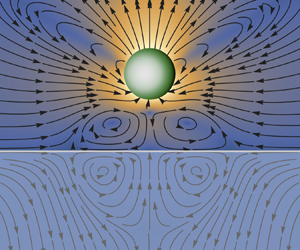
 $h>h_{{min}}=1.3$. This is because, very close to the interface, other effects such as electric double-layer and Van der Waals interactions are expected to dominate (Wu & Bevan Reference Wu and Bevan2005; Verweij et al. Reference Verweij, Ketzetzi, De Graaf and Kraft2020). As expected, a higher chemical diffusivity ratio of the interface, and thus decreased chemical repulsion from it, requires higher particle activities for hovering to remain possible; see figure 5 for an illustration of this effect using the method of images for the concentration field. It is also evident that lower levels of activity are sufficient for hovering above a free surface as compared with a solid wall. This is intuitive when considering that due to increased fluid internal friction flows near a wall decay faster than near a free surface (Aderogba & Blake Reference Aderogba and Blake1978) and so it is easier for a particle near a free surface to drive flows that make it hover. Using the method of images for Stokes flows this is illustrated in figure 6.
Hovering above an interface. We show the hovering height  $h$ (pseudo-colour map) for an active particle at zero temperature as a function of its activity
 $\mathcal {A}_{G}$ and the diffusivity ratio
 $\lambda ^{c}$ or the viscosity ratio
 $\lambda ^{f}$ of the interface. In panel (a) we consider the particle hovering above a wall (
 $\lambda ^{f}\rightarrow \infty$) that is permeable to the solutes. For a boundary between regions of equal solute diffusivity (
 $\lambda ^{c}=1$) there exists no chemical repulsion, leading to the particle inevitably crashing into the boundary. Therefore, we only consider values
 $\lambda ^{c} \, \leq 0.99$. The red line shows the particle's minimum activity to hover at a minimum height of
 $h_{{min}}=1.3$ as a function of the diffusivity ratio. The white region below the red line indicates physics that is not accessible in our simplified model and we assume that the particle crashes into the boundary due to gravity, i.e. we set
 $h=1$. The two dashed grey lines indicate the limiting values
 $\mathcal {A}_{G}^{1}\approx 500$ and
 $\mathcal {A}_{G}^{2}\approx 10^{5}$ that are required to hover above an impermeable and a highly permeable wall. In panel (b) we consider the particle hovering above an impermeable (
 $\lambda ^{c}=0$) interface of varying viscosity ratio. The two horizontal dashed grey lines indicate the limiting values
 $\mathcal {A}_{G}^{3}\approx 3$ and
 $\mathcal {A}_{G}^{1}$ that are required to hover above a free surface and a solid wall, respectively.

Solute concentration for a particle hovering above a permeable boundary. The chemical field generated by a hovering source particle (green) is shown above ( $z>0$) and below (
 $z<0$) the permeable (
 $\lambda ^{c}=0.3$) boundary as a pseudo-colour map, where contours indicate regions of constant concentration. We emphasise that the net concentration (right panel) in the region containing the particle is a superposition of the source without the boundary present (a) and its image below the boundary (b). The net concentration below the permeable boundary is then generated by the appropriate boundary conditions. To imply a change in the chemical diffusivity
 $D_{2}=\lambda ^{c}D_{1}$ the colour map for the region
 $z<0$ is shown with slightly reduced opacity. Since source particles want to move down chemical gradients (anti-chemotaxis), it is clear that the image creates a repulsive concentration field in
 $z>0$, making it possible for the particle to hover above the boundary. It is worth noting that, for an impermeable boundary (
 $\lambda ^{c}=0$), the contour lines meet the boundary at a right angle and the corresponding vector field (
 $\boldsymbol {\nabla }c$) becomes purely tangential to this ‘no-flux’ boundary. In the limit of rapid solute diffusion the viscosity ratio of the interface has no influence on the chemical field.

Fluid flow for a particle hovering above a fluid–fluid interface. The fluid flow (laboratory frame) generated by a hovering source particle (green) is shown above ( $z>0$) and below (
 $z<0$) a chemically permeable fluid–fluid interface (
 $\lambda ^{c}=0.3, \lambda ^{f}=10$). The direction of the fluid flow is indicated by black arrows, while its relative magnitude is implied by the overlaid pseudo-colour map. The net flow (c) in the region containing the particle is a superposition of the source without the boundary conditions on the fluid flow and stress (a) and its image below the boundary (b). Note that for the source the chemical boundary conditions must still be satisfied (see the net chemical field in figure 5), inducing a non-trivial slip on the otherwise isotropic particle. The net flow below the interface is then driven by the appropriate velocity and stress boundary conditions. To imply a change in the viscosity
 $\eta _{2}=\lambda ^{f}\eta _{1}$ the colour map for the region
 $z<0$ is shown with slightly reduced opacity. It is clear that the image produces an upwards flow in
 $z>0$ which balances gravity and makes the particle hover away from the interface. In the net flow this creates convection rolls between the particle and the interface which in turn drive convection rolls below the interface.

5. Discussion
In this paper, we have presented a simultaneous solution of the BIEs describing the chemical and the fluid flow around an autophoretic particle in a fluctuating environment. This has been achieved in a basis of TSH. Compared with the common squirmer model approach to active particles (Lighthill Reference Lighthill1952; Blake Reference Blake1971; Pak & Lauga Reference Pak and Lauga2014; Pedley, Brumley & Goldstein Reference Pedley, Brumley and Goldstein2016), our boundary-domain integral method offers the distinct advantage of obtaining the traction on the particle directly in a complete orthonormal basis. This provides a naturally kinetic approach via Newton's equations in which thermal fluctuations manifest themselves as fluctuating stresses. The Brownian motion of an autophoretic particle is obtained in terms of coupled roto-translational stochastic update equations containing mobility and propulsion tensors. The latter are found to arise from chemical activity of the particle and the chemo-hydrodynamic coupling at the particle's surface, inducing a coupling of slip modes. We have obtained exact and leading-order solutions for both the chemical and the fluctuating hydrodynamic problems far away from and in the vicinity of boundaries, respectively. Studying the Brownian motion of particles in the bulk, some of the flexibility of our method in particle design has been demonstrated. In the case of autophoresis near a plane interface, characterised by its solute diffusivity and viscosity ratios, we have provided analytical expressions for the chemo-hydrodynamic coupling tensors. The given mobilities ensure a positive–definite diffusion matrix in stochastic simulations. Finally, we have studied the hovering state of an isotropic phoretic particle above an interface as a function of particle activity, and the diffusivity and viscosity ratios of the interface. In doing so, we have provided numerical results as well as physical insights into the repulsive chemo-hydrodynamic particle–interface interactions.
We have given the leading-order results for the chemical and hydrodynamic coupling tensors. In principle, these can be obtained to arbitrary accuracy, and the general iterative solutions are given in the Appendix. This non-trivial computation will be the topic of future work. While our results in § 3.2 are guaranteed to provide dissipative motion for physical configurations, in Brownian simulations, unphysical situations with a non-zero particle–boundary overlap may occur on occasion (the probability of which can be lowered by imposing a short-range repulsive potential between the particle and the boundary). In this case, one can either impose an ad hoc regularisation on the mobility (Wajnryb et al. Reference Wajnryb, Mizerski, Zuk and Szymczak2013; Balboa Usabiaga, Delmotte & Donev Reference Balboa Usabiaga, Delmotte and Donev2017; Singh & Adhikari Reference Singh and Adhikari2017) or use a bounce-back condition, effectively implementing a reflective boundary condition in the simulation (Volpe, Gigan & Volpe Reference Volpe, Gigan and Volpe2014).
It is helpful to compare our results with previous work on chemical and hydrodynamic interactions of an active particle in a fluctuating fluid. We have shown that simultaneous harmonic expansions of the surface fields provide a high degree of flexibility in particle design, comparable to previous models capable of motion in three dimensions (Lisicki et al. Reference Lisicki, Reigh and Lauga2018). Additionally, our framework has been shown to provide a straightforward way of studying the Brownian dynamics of particles that, even in the limit of zero temperature, perform complex motion (van Teeffelen & Löwen Reference van Teeffelen and Löwen2008; Mozaffari et al. Reference Mozaffari, Sharifi-Mood, Koplik and Maldarelli2018; Bailey et al. Reference Bailey, Gutiérrez, Martín-Roca, Niggel, Carrasco-Fadanelli, Buttinoni, Pagonabarraga, Isa and Valeriani2024). To the best of our knowledge, this is the first work to obtain the elastance for an active particle near an interface separating two fluids of arbitrary diffusivity ratios. The corresponding Green's function, which is given in table 3, does not appear anywhere in the literature, although its derivation is straightforward given the correct boundary conditions. This paper is also the first to simultaneously study the chemo-hydrodynamics of an autophoretic particle near a planar surface of two immiscible fluids of arbitrary ratio of viscosities and diffusivities. While previous works have studied phoretic particles hovering above a chemically impermeable solid wall as a function of particle coverage (Uspal et al. Reference Uspal, Popescu, Dietrich and Tasinkevych2015; Ibrahim & Liverpool Reference Ibrahim and Liverpool2016), we investigated the hovering state as a function of the properties of the interface, relevant for studies on particle aggregation near fluid–fluid or free surfaces (Chen et al. Reference Chen, Yang, Yang and Zhang2015; Hokmabad et al. Reference Hokmabad, Nishide, Ramesh, Krüger and Maass2022).
We briefly discuss the level of approximation of explicit results provided in this paper. For a passive particle, the mobility of sedimentation towards a plane interface is known exactly (Brenner Reference Brenner1961). In the absence of an exact solution for motion parallel to a boundary, careful examination of the case when the particle–interface gap distance is much smaller than the particle radius is necessary. In 1967, Goldman et al. (Goldman, Cox & Brenner Reference Goldman, Cox and Brenner1967) used a lubrication approximation to derive an asymptotic solution for this case. However, matching the asymptotic solutions for the near- ( $h/b\ll 1$) and far-field (
 $h/b\gg 1$) limits can be challenging in dynamic simulations (Brady & Bossis Reference Brady and Bossis1988; Ichiki Reference Ichiki2002). It has been confirmed experimentally that, for parallel motion, the order to which the mobilities are given in this paper provides a good approximation even when the particle–interface gap distance is only a fraction of the particle radius (Choudhury et al. Reference Choudhury, Straube, Fischer, Gibbs and Höfling2017). So while an approach using lubrication theory is appropriate for general motion very close to a plane (Villa et al. Reference Villa, Boniello, Stocco and Nobili2020, Reference Villa, Blanc, Daddi-Moussa-Ider, Stocco and Nobili2023), the given approximation in the mobilities arising from a series expansion can still be expected to be of interest to a wide range of experimental settings in which colloidal particles are studied near a plane boundary. Thus, our work also adds to the existing literature on the mobility (Brenner Reference Brenner1961; Goldman et al. Reference Goldman, Cox and Brenner1967; Felderhof Reference Felderhof1976; Lee et al. Reference Lee, Chadwick and Leal1979; Lee & Leal Reference Lee and Leal1980; Perkins & Jones Reference Perkins and Jones1990, Reference Perkins and Jones1992; Swan & Brady Reference Swan and Brady2007; Michailidou et al. Reference Michailidou, Petekidis, Swan and Brady2009; Daddi-Moussa-Ider et al. Reference Daddi-Moussa-Ider, Lisicki, Hoell and Löwen2018) and diffusion (Ermak & McCammon Reference Ermak and McCammon1978; Wajnryb et al. Reference Wajnryb, Szymczak and Cichocki2004; Rogers et al. Reference Rogers, Lisicki, Cichocki, Dhont and Lang2012; Delong, Balboa Usabiaga & Donev Reference Delong, Balboa Usabiaga and Donev2015; Lisicki, Cichocki & Wajnryb Reference Lisicki, Cichocki and Wajnryb2016) of a sedimenting particle near a boundary. Explicit expressions for propulsion tensors and mobility matrices are given in table 5, while table 4 contains the corresponding chemical connectors near an interface. These will be helpful in Langevin simulations of autophoretic particles in various experimentally realisable settings and for studying fluctuating trajectories of an active particle including both chemical and hydrodynamic interactions.
Aside from its intrinsic theoretical significance, the single-body solution (exact away from boundaries and approximate in complex environments) holds potential value in numerically solving the BIE for multiple particles. This is due to the ability to initiate numerical iterations with the single-body solution. For problems falling under this category, discretised versions of the BIEs result in diagonally dominant linear systems. Notably, the one-body solution serves as the solution in cases where hydrodynamic interactions are disregarded. This implies that starting iterations from the one-body solution can lead to rapid convergence towards diagonally dominant numerical solutions (Singh & Adhikari Reference Singh and Adhikari2018). In scenarios involving multiple interacting particles, utilising a basis of TSH for expanding surface fields offers distinct advantages over other bases like spherical or vector spherical harmonics, including reduced computational cost due to covariance under rotations (Greengard & Rokhlin Reference Greengard and Rokhlin1987; Damour & Iyer Reference Damour and Iyer1991; Applequist Reference Applequist2002; Turk Reference Turk2023). The condition for tangential slip flow in terms of TSH in (3.24) now connects in a straightforward way the formalism for general slip (restricted by mass conservation only) used in previous works (Ghose & Adhikari Reference Ghose and Adhikari2014; Singh et al. Reference Singh, Ghose and Adhikari2015; Singh & Adhikari Reference Singh and Adhikari2018; Singh et al. Reference Singh, Adhikari and Cates2019; Turk et al. Reference Turk, Singh and Adhikari2022) to the present and other problems in which tangential slip is considered, e.g. active drops.
In future work we will analytically and numerically build upon the theoretical results contained in this paper. A detailed analysis of the dynamical system in (3.17) governing autophoresis near an interface might reveal features such as intricate, thermally limited bound states (Mozaffari et al. Reference Mozaffari, Sharifi-Mood, Koplik and Maldarelli2018; Bolitho, Singh & Adhikari Reference Bolitho, Singh and Adhikari2020) potentially relevant to the study of biofilm formation in bacteria (Wilking et al. Reference Wilking, Angelini, Seminara, Brenner and Weitz2011; Persat et al. Reference Persat, Nadell, Kim, Ingremeau, Siryaporn, Drescher, Wingreen, Bassler, Gitai and Stone2015). Removing the assumption of rapid diffusion gives rise to nonlinear advection–diffusion coupling, uncovering a range of potential applications such as the intricate dynamics of active droplets (Herminghaus et al. Reference Herminghaus, Maass, Krüger, Thutupalli, Goehring and Bahr2014; Michelin Reference Michelin2023). These and more provide exciting avenues for future research.
Acknowledgements
We thank Professors M.E. Cates, I. Pagonabarraga and H.A. Stone for many helpful discussions. We also thank two anonymous referees for their feedback and constructive criticism, which led to an improvement in the presentation of our results.
Funding
G.T. was funded in part by NSF through the Princeton University (PCCM) Materials Research Science and Engineering Center DMR-2011750 (co-PI is H.A. Stone), a David Crighton Fellowship by the Department of Applied Mathematics and Theoretical Physics at the University of Cambridge to conduct research in the Department of Physics at the Indian Institute of Technology, Madras, India, and by the Engineering and Physical Sciences Research Council (project reference no. 2089780). R.S. acknowledges support from the Indian Institute of Technology, Madras, India and their seed and initiation grants as well as a Start-up Research Grant, SERB, India (SERB file number: SRG/2022/000682).
Declaration of interests
The authors report no conflict of interest.
Appendix A. Chemical problem
A.1. Exact solution for integral equations
As discussed in a previous work (Singh et al. Reference Singh, Adhikari and Cates2019) using Galerkin's method, the BIE (IIa) can be expressed as the linear system
 \begin{equation} \tfrac{1}{2}\boldsymbol{C}^{(q)}=\boldsymbol{C}^{\infty(q)}+\boldsymbol{\mathcal{H}}^{(q,q')}\odot\boldsymbol{J}^{(q')}+\boldsymbol{\mathcal{L}}^{(q,q')}\odot\boldsymbol{C}^{(q')},\end{equation}
with the matrix elements
 $$\begin{gather} \boldsymbol{\mathcal{H}}^{(q,q')}(\boldsymbol{R},\tilde{\boldsymbol{R}})= \tilde{w}_{q}\tilde{w}_{q'}\int\boldsymbol{Y}^{(q)}(\hat{\boldsymbol{b}})H(\boldsymbol{R}+\boldsymbol{b},\tilde{\boldsymbol{R}}+\boldsymbol{b}') \boldsymbol{Y}^{(q')}(\hat{\boldsymbol{b}}')\,{\rm d}S\,{\rm d}S', \end{gather}$$
 $$\begin{gather}\boldsymbol{\mathcal{L}}^{(q,q')}(\boldsymbol{R},\tilde{\boldsymbol{R}})=\tilde{w}_{q}w_{q'}\int\boldsymbol{Y}^{(q)}(\hat{\boldsymbol{b}})\hat{\boldsymbol{b}}'\boldsymbol{\cdot}\boldsymbol{L}(\boldsymbol{R}+\boldsymbol{b},\tilde{\boldsymbol{R}}+\boldsymbol{b}')\boldsymbol{Y}^{(q')}(\hat{\boldsymbol{b}}')\,{\rm d}S\,{\rm d}S'. \end{gather}$$
Here, we evaluate these integrals for an unbounded domain, when  $H=H^{o}(\boldsymbol {r})$ (see (3.5)) and
 $\boldsymbol {L}=\boldsymbol {L}^{o}(\boldsymbol {r})$, given by
 $\boldsymbol {L}^{o}(\boldsymbol {r})=\hat {\boldsymbol {r}}/4{\rm \pi} r^{2}$. The matrix elements for the unbounded domain have singular but integrable kernels. Due to their translational invariance they can be solved using Fourier techniques. The derivation follows analogous steps to the one of the exact solution for the Stokes traction for an isolated active particle in Turk et al. (Reference Turk, Singh and Adhikari2022). Writing
 $\boldsymbol {\mathcal {H}}^{o(q,q')}$ and
 $\boldsymbol {\mathcal {L}}^{o(q,q')}$ for the corresponding matrix elements, we find
 \begin{align} \mathcal{H}_{QQ'}^{o(q,q')}&=\sum_{n,n'=0}^{\infty}\tau_{nn'qq'}\int{\rm d}S\,Y_{Q}^{(q)}(\hat{\boldsymbol{b}})Y_{N}^{(n)}(\hat{\boldsymbol{b}})\int{\rm d}S\,'Y_{Q'}^{(q')}(\hat{\boldsymbol{b}}')Y_{N'}^{(n')}(\hat{\boldsymbol{b}}')\nonumber\\ &\quad\times\int{\rm d}k\,j_{n}(kb)j_{n'}(kb)\int{\rm d}\varOmega_{k}\,Y_{N}^{(n)}(\hat{\boldsymbol{k}})k^{2}\hat{H}^{o}(\boldsymbol{k})Y_{N'}^{(n')}(\hat{\boldsymbol{k}}), \end{align}
for the single layer and similarly for the double layer
 \begin{align} \mathcal{L}_{QQ'}^{o(q,q')}&=\sum_{l,l'=0}^{\infty}\tau_{nn'qq'}\int{\rm d}S\,Y_{Q}^{(q)} (\hat{\boldsymbol{b}})Y_{N}^{(n)}(\hat{\boldsymbol{b}})\int{\rm d}S'\ Y_{Q'}^{(q')}(\hat{\boldsymbol{b}}')Y_{N'}^{(n')} (\hat{\boldsymbol{b}}')\boldsymbol{Y}^{(1)}(\hat{\boldsymbol{b}}')\nonumber\\ &\quad \times\int{\rm d}k\,kj_{n}(kb)j_{n'}(kb)\int{\rm d}\varOmega_{k}\,Y_{N}^{(n)}(\hat{\boldsymbol{k}})k\hat{\boldsymbol{L}}^{o}(\boldsymbol{k})Y_{N'}^{(n')} (\hat{\boldsymbol{k}}). \end{align}
Here, we have defined  $\tau _{nn'qq'}=({2b^{4}}/{{\rm \pi} })i^{n+3n'}\tilde {w}_{q}\tilde {w}_{q'}w_{n}\tilde {w}_{n}w_{n'}\tilde {w}_{n'}$ and used the Fourier transforms of the Green's functions for the unbounded domain
 \begin{equation} \hat{H}^{o}(\boldsymbol{k})=\frac{1}{D}\frac{1}{k^{2}},\quad \hat{\boldsymbol{L}}^{o}(\boldsymbol{k})=i\frac{\hat{\boldsymbol{k}}}{k}. \end{equation}
The functions  $j_{n}(kb$) are spherical Bessel functions,
 $b=|\boldsymbol {b}|$ and
 $i=\sqrt {-1}$ is the imaginary unit. Further,
 $\int \textrm {d}S$ implies an integral over the surface of a sphere with radius
 $b$,
 $\int \textrm {d}\varOmega$ the integral over the surface of a unit sphere and
 $\int \textrm {d}k$ a scalar definite integral from
 $0$ to
 $\infty$. Evaluating these expressions, we find that the single- and double-layer matrix elements diagonalise simultaneously in a basis of TSH such that
 \begin{equation} \boldsymbol{\mathcal{H}}^{o(q,q')}\odot\boldsymbol{J}^{(q')}=\frac{1}{4{\rm \pi} bDw_{q}}\boldsymbol{J}^{(q)},\quad\boldsymbol{\mathcal{L}}^{o(q,q')}\odot\boldsymbol{C}^{(q')}={-}\frac{1}{2(2q+1)}\boldsymbol{C}^{(q)}. \end{equation}
The linear system in (A1) can then be solved trivially. We find the exact result, valid for an arbitrary mode index  $q$
 \begin{equation} \boldsymbol{C}^{(q)}=\zeta_{q}\boldsymbol{C}^{\infty(q)}+\mathcal{E}_{q}\boldsymbol{J}^{(q)},\end{equation}
with  $\zeta _{q}$ and
 $\mathcal {E}_{q}$ given in (A7). In deriving this result, we corrected an error in the double-layer calculation given in Singh et al. (Reference Singh, Adhikari and Cates2019).
For the matrix elements due to additional boundary conditions with the propagator  $H^{*}$ and the corresponding double layer
 $L^{*}$ it is known that (A2) evaluate to (Singh et al. Reference Singh, Adhikari and Cates2019)
 \begin{align} \boldsymbol{\mathcal{H}}^{*(q,q')}=b^{q+q'}\boldsymbol{\nabla}^{(q)}\tilde{\boldsymbol{\nabla}}^{(q')}H^{*} (\boldsymbol{R},\tilde{\boldsymbol{R}}),\quad\boldsymbol{\mathcal{L}}^{*(q,q')}=\frac{4{\rm \pi} bD}{(q'-1)!(2q'+1)!!}\boldsymbol{\mathcal{H}}^{*(q,q')},\end{align}
where we have left the point of evaluation,  $\boldsymbol {R}=\tilde {\boldsymbol {R}}$ for the one-body problem, implicit for brevity, and where
 $\boldsymbol {\mathcal {L}}^{*(q,q')}$ is defined for
 $q'\geq 1$.
A.2. Iterative solution in complex environments
The formal solution of the BIE for the concentration field in (IId) in a basis of TSH gives the following for the linear response to a background concentration field:
 \begin{equation} \boldsymbol{\zeta}^{(q,q')}=\left[\boldsymbol{A}^{{-}1}\right]^{(q,q')},\quad{\rm where}\ \boldsymbol{A}^{(q,q')}=\left(\tfrac{1}{2}\boldsymbol{I}-\boldsymbol{\mathcal{L}}\right)^{(q,q')}. \end{equation}
This can be computed using Jacobi's iterative method of matrix inversion. At the  $n$th iteration, we find
 \begin{multline}
\left(\boldsymbol{\zeta}^{(q,q')}\right)^{[n]}=\left(\boldsymbol{A}^{(q,q)}\right)^{-1}\Big[\boldsymbol{I}^{(q,q')}-\sum^{'}\boldsymbol{A}^{(q,q'')}\left(\boldsymbol{\zeta}^{(q'',q')}\right)^{[n-1]}\Big],\\[0.5em]
{\text{with}}\quad\left(\boldsymbol{\zeta}^{(q,q')}\right)^{[0]}=\zeta_{q}\boldsymbol{I}^{(q,q')}.
\end{multline}
The primed sum implies that diagonal terms with  $q=q''$ are not included. Naturally, we choose the solution in the unbounded domain as the zeroth-order solution. Similarly, it is known that at the
 $n$th iteration the elastance in a basis of TSH is given by (Singh et al. Reference Singh, Adhikari and Cates2019)
 \begin{multline}
\left(\boldsymbol{\mathcal{E}}^{(q,q')}\right)^{[n]}=\left(\boldsymbol{A}^{(q,q)}\right)^{-1}\Big[\boldsymbol{\mathcal{H}}^{(q,q')}-\sum^{'}\boldsymbol{A}^{(q,q'')}\left(\boldsymbol{\mathcal{E}}^{(q'',q')}\right)^{[n-1]}\Big],\\[0.5em]
{\text{with}}\quad\left(\boldsymbol{\mathcal{E}}^{(q,q')}\right)^{[0]}=\mathcal{E}_{q}\boldsymbol{I}^{(q,q')}.
\end{multline}
To first order in the iteration this yields the expressions given in (3.8) and (3.9), with an error  $O_{a}$ given in table 7.
A.3. Chemo-hydrodynamic coupling
The chemo-hydrodynamic coupling tensors in a basis of TSH in (Ih) and (3.26) are in general given by the surface integral
 \begin{align} \boldsymbol{\chi}^{(l,q)}=\frac{1}{b}\tilde{w}_{l-1}\sum_{q'=0}^{\infty}w_{q}\tilde{w}_{q'}\boldsymbol{M}^{(q')} \int\left\{\!(q+1)\boldsymbol{Y}^{(1)}\boldsymbol{Y}^{(l-1)}\boldsymbol{Y}^{(q')} \boldsymbol{Y}^{(q)}-\boldsymbol{Y}^{(l-1)}\boldsymbol{Y}^{(q')}\boldsymbol{Y}^{(q+1)}\!\right\} {\rm d}S.\end{align}
For the leading polar, chiral and symmetric modes of slip we have evaluated them in (3.29). This corrects a previously erroneous result (Singh et al. Reference Singh, Adhikari and Cates2019).
Appendix B. Hydrodynamic problem and rigid-body motion
In the following we include the rigid-body motion of the particle,  $\boldsymbol {v}^{\mathcal {D}}(\boldsymbol {b})=\boldsymbol {V}+\boldsymbol {\varOmega }\times \boldsymbol {b}$, in the expansion in (3.10a,b) such that
 $\boldsymbol {V}^{(1s)}=\boldsymbol {V}-\boldsymbol {V}^{\mathcal {A}}$ and
 $\boldsymbol {V}^{(2a)}/2b=\boldsymbol {\varOmega }-\boldsymbol {\varOmega }^{\mathcal {A}}$ for simplicity of notation. As discussed in previous work using a Galerkin method (Singh et al. Reference Singh, Ghose and Adhikari2015), the BIE (IIf) for Stokes flow without thermal fluctuations can be expressed as the linear system
 \begin{equation} \tfrac{1}{2}\boldsymbol{V}^{(l\sigma)}={-}\boldsymbol{\mathcal{G}}^{(l\sigma,l^{\prime}\sigma^{\prime})}\odot\boldsymbol{F}^{(l^{\prime}\sigma^{\prime})}+\boldsymbol{\mathcal{K}}^{(l\sigma,l^{\prime}\sigma^{\prime})}\odot\boldsymbol{V}^{(l^{\prime}\sigma^{\prime})}.\end{equation}
The matrix elements corresponding to the single- and double-layer integrals are
 $$\begin{gather} \boldsymbol{\mathcal{G}}^{(l,l^{\prime})}(\boldsymbol{R},\tilde{\boldsymbol{R}}) =\tilde{w}_{l-1}\tilde{w}_{l'-1}\int\boldsymbol{Y}^{(l-1)}(\hat{\boldsymbol{b}})\boldsymbol{G}(\boldsymbol{R}+\boldsymbol{b},\tilde{\boldsymbol{R}}+\boldsymbol{b}^{\prime})\boldsymbol{Y}^{(l^{\prime}-1)}(\hat{\boldsymbol{b}}^{\prime})\,{\rm d}S\,{\rm d}S^{\prime}, \end{gather}$$
 $$\begin{gather}\boldsymbol{\mathcal{K}}^{(l,l^{\prime})}(\tilde{\boldsymbol{R}},\boldsymbol{R}) =\tilde{w}_{l-1}w_{l'-1} \int\boldsymbol{Y}^{(l-1)}(\hat{\boldsymbol{b}})\boldsymbol{K}(\tilde{\boldsymbol{R}}+\boldsymbol{b}^{\prime}, \boldsymbol{R}+\boldsymbol{b})\boldsymbol{\cdot}\hat{\boldsymbol{b}}^{\prime}\boldsymbol{Y}^{(l^{\prime}-1)}(\hat{\boldsymbol{b}}^{\prime})\,{\rm d}S\,{\rm d}S^{\prime}. \end{gather}$$
In defining the double-layer matrix element it is worthwhile noting the following. Both double-layer integrals (IIc) and (IIh) in table 2 are defined as improper integrals when  $\boldsymbol {r}\in S$, usually referred to as the principal value. This definition differs from the Cauchy principal value of a singular one-dimensional integral. While the latter requires excluding small intervals around the singularity and taking the limit as their size tends to zero simultaneously, the double-layer integrals both are weakly singular (given
 $S$ is a Lyapunov surface), and so their principal value exists in the usual sense of an improper integral and is a continuous function in
 $\boldsymbol {r}\in S$ (Pozrikidis Reference Pozrikidis1992; Kim & Karrila Reference Kim and Karrila2005).
Writing the matrix elements as a sum of unbounded and correction terms, it is known that they evaluate to (Singh et al. Reference Singh, Ghose and Adhikari2015; Turk et al. Reference Turk, Singh and Adhikari2022)
 \begin{align} \boldsymbol{\mathcal{G}}^{(l,l^{\prime})} &=\boldsymbol{\mathcal{G}}^{o(l,l^{\prime})}+\boldsymbol{\mathcal{G}}^{*(l,l^{\prime})}=\boldsymbol{\mathcal{G}}^{o(l,l^{\prime})}+b^{l+l^{\prime}-2}\mathcal{F}^{l-1}\tilde{\mathcal{F}}^{l^{\prime}-1}\boldsymbol{\nabla}^{(l-1)}\tilde{\boldsymbol{\nabla}}^{(l^{\prime}-1)}\boldsymbol{G}^{*}(\boldsymbol{R},\tilde{\boldsymbol{R}}),\end{align}
 \begin{align} \boldsymbol{\mathcal{K}}^{(l,l^{\prime})} & =\boldsymbol{\mathcal{K}}^{o(l,l^{\prime})}+ \boldsymbol{\mathcal{K}}^{*(l,l^{\prime})} \nonumber\\ & =\boldsymbol{\mathcal{K}}^{o(l,l^{\prime})}+\frac{4{\rm \pi} b^{l+l^{\prime}-1}}{(l^{\prime}-2)!(2l^{\prime}-1)!!}\mathcal{F}^{l-1}\tilde{\mathcal{F}}^{l^{\prime}-1}\boldsymbol{\nabla}^{(l-1)}\tilde{\boldsymbol{\nabla}}^{(l^{\prime}-2)}\boldsymbol{K}^{*}(\tilde{\boldsymbol{R}},\boldsymbol{R}). \end{align}
These expressions are exact for a spherical particle.
Defining the column vectors for the force and torque acting on the particle  $\boldsymbol {F}^{A}=(\boldsymbol {F}^{(1s)},\boldsymbol {F}^{(2a)})^{\textrm {tr}},$ the higher moments of traction
 $\boldsymbol {F}^{B}=(\boldsymbol {F}^{(2s)},\boldsymbol {F}^{(3t)},\dots )^{\textrm {tr}}$, the modes corresponding to rigid-body motion
 $\boldsymbol {V}^{A}=(\boldsymbol {V}^{(1s)},\boldsymbol {V}^{(2a)})^{\textrm {tr}}$ and the higher modes of the slip
 $\boldsymbol {V}^{B}=(\boldsymbol {V}^{(2s)},\boldsymbol {V}^{(3t)},\dots )^{\textrm {tr}}$, we can write the linear system as (Singh et al. Reference Singh, Ghose and Adhikari2015)
 \begin{equation} \frac{1}{2}\begin{pmatrix}\boldsymbol{V}^{A}\\ \boldsymbol{V}^{B} \end{pmatrix}={-}\begin{pmatrix}\boldsymbol{\mathcal{G}}^{AA} & \boldsymbol{\mathcal{G}}^{AB}\\ \boldsymbol{\mathcal{G}}^{BA} & \boldsymbol{\mathcal{G}}^{BB} \end{pmatrix}\begin{pmatrix}\boldsymbol{F}^{A}\\ \boldsymbol{F}^{B} \end{pmatrix}+\begin{pmatrix}\boldsymbol{\mathcal{K}}^{AA} & \boldsymbol{\mathcal{K}}^{AB}\\ \boldsymbol{\mathcal{K}}^{BA} & \boldsymbol{\mathcal{K}}^{BB} \end{pmatrix}\begin{pmatrix}\boldsymbol{V}^{A}\\ \boldsymbol{V}^{B} \end{pmatrix}.\end{equation}
To be able to solve this infinite linear system, we need to truncate the mode expansions (3.10a,b) at some appropriate order, and fix the gauge freedom in the traction. Taking care of the latter, we impose  $\int \boldsymbol {f}^{H}\boldsymbol {\cdot }\hat {\boldsymbol {b}}\,\textrm {d}S=-\int p\,\textrm {d}S=0$, which is equivalent to imposing
 $F^{(2t)}=0$. The rationale behind this can be explained as follows. The pressure is a harmonic function, i.e.
 $\nabla ^{2}p=0$, and can thus be expanded in a basis constructed from derivatives of
 $1/r$. The leading mode of such an expansion decays as
 $1/r$ and its expansion coefficient is obtained from the integral
 $\int p\,\textrm {d}S$. Further, incompressibility, and the absence of sinks and sources of fluid render the pressure a non-dynamical quantity, meaning that the fundamental solution for the fluid flow
 $\boldsymbol {v}$ is independent of the pressure and decays as
 $1/r$. However, Stokes equation (Id) must still be satisfied, and a pressure term decaying as
 $1/r$ would violate it. We thus impose
 $\int p\,\mathrm {d}S=0$, rendering the single-layer operator invertible. Eliminating the unknown
 $\boldsymbol {F}^{B}$, we can directly solve for the rigid-body motion of the particle
 \begin{equation} \boldsymbol{V}^{A}={-}\mathbb{M}\boldsymbol{\cdot}\boldsymbol{F}^{A}+\boldsymbol{\varPi}\odot\boldsymbol{V}^{B},\end{equation}
where we have defined the grand mobility matrix  $\mathbb {M}$ and the grand propulsion tensor
 $\boldsymbol {\varPi }$,
 \begin{align} \mathbb{M}=\left[\boldsymbol{\mathcal{G}}^{AA}-\boldsymbol{\mathcal{G}}^{AB}\left(\boldsymbol{\mathcal{G}}^{BB}\right)^{{-}1} \boldsymbol{\mathcal{G}}^{BA}\right],\quad\boldsymbol{\varPi}=\left[\boldsymbol{\mathcal{K}}^{AB}+ \boldsymbol{\mathcal{G}}^{AB}\left(\boldsymbol{\mathcal{G}}^{BB}\right)^{{-}1} \left(\tfrac{1}{2}\boldsymbol{I}-\boldsymbol{\mathcal{K}}^{BB}\right)\right].\end{align}
In finding this solution, we have used that rigid-body motion lies in the eigenspace of the double layer matrix element with a uniform eigenvalue of  $-1/2$, and that no exterior flows are produced for the rigid-body component of the motion such that
 \begin{equation} \boldsymbol{\mathcal{K}}^{AA}\boldsymbol{V}^{A}={-}\tfrac{1}{2}\boldsymbol{V}^{A},\quad \boldsymbol{\mathcal{K}}^{BA}\boldsymbol{V}^{A}=\boldsymbol{0}. \end{equation}
Equation (B6a,b) guarantees a positive–definite mobility matrix given that every principal sub-matrix of a positive–definite matrix (here,  $\boldsymbol {\mathcal {G}}^{(l \sigma,l^{\prime }\sigma ^{\prime })}$) is positive–definite itself. Comparing (3.17) and (B6a,b) we can directly identify the mobility and propulsion tensors in terms of the matrix elements in (B2). For the mobilities we find
 \begin{equation} \boldsymbol{\mu}^{\alpha\beta}=\frac{1}{c^{\alpha}q^{\beta}}\left[\boldsymbol{\mathcal{G}}^{(l\sigma,l^{\prime}\sigma^{\prime})}-\sum_{l^{\prime\prime}\sigma^{\prime\prime}=2s}\boldsymbol{\mathcal{G}}^{(l\sigma,l^{\prime\prime}\sigma^{\prime\prime})}\boldsymbol{\varUpsilon}{}^{(l^{\prime\prime}\sigma^{\prime\prime},l^{\prime}\sigma^{\prime})}\right], \end{equation}
with  $\alpha =T,R$ implying
 $l\sigma =1s,2a$ and
 $\beta =T,R$ implying
 $l^{\prime }\sigma ^{\prime }=1s,2a$, respectively. The scalar pre-factors
 $c^{\alpha }$ and
 $q^{\beta }$ can be found in table 6. Similarly, we find for the propulsion tensors
 \begin{equation} \boldsymbol{\rm \pi}^{(\alpha,l^{\prime}\sigma^{\prime})}=\frac{1}{c^{\alpha}} \left[\boldsymbol{\mathcal{K}}^{(l\sigma,l^{\prime}\sigma^{\prime})}+\sum_{l^{\prime\prime}\sigma^{\prime\prime}=2s}\boldsymbol{\mathcal{G}}^{(l\sigma,l^{\prime\prime}\sigma^{\prime\prime})}\boldsymbol{\varPhi}^{(l^{\prime\prime}\sigma^{\prime\prime},l^{\prime}\sigma^{\prime})}\right].\end{equation}
The propulsion tensors are defined for  $l^{\prime }\sigma ^{\prime }\geq 2s$ as follows directly from the equations of motion (3.17). In (B8) and (B9) we have defined
 \begin{align} \boldsymbol{\varUpsilon}^{(l\sigma,l^{\prime}\sigma^{\prime})} &=\sum_{l^{\prime\prime}\sigma^{\prime\prime}=2s} \left(\boldsymbol{\mathcal{G}}^{(l\sigma,l^{\prime\prime}\sigma^{\prime\prime})}\right)^{{-}1} \boldsymbol{\mathcal{G}}^{(l^{\prime\prime}\sigma^{\prime\prime},l^{\prime}\sigma^{\prime})}, \end{align}
 \begin{align} \boldsymbol{\varPhi}^{(l\sigma,l^{\prime}\sigma^{\prime})} & = \sum_{l^{\prime\prime}\sigma^{\prime\prime}=2s}\left(\boldsymbol{\mathcal{G}}^{(l\sigma,l^{\prime\prime}\sigma^{ \prime\prime})}\right)^{{-}1}\left(\frac{1}{2}\boldsymbol{I}-\boldsymbol{\mathcal{K}}\right)^{(l^{\prime\prime}\sigma^{\prime\prime},l^{\prime}\sigma^{\prime})}\nonumber\\ &=\sum_{l^{\prime\prime}\sigma^{\prime\prime}=2s}\left(\boldsymbol{\mathcal{G}}^{(l\sigma,l^{\prime\prime}\sigma^{\prime\prime})}\right)^{{-}1}\mathcal{\boldsymbol{B}}^{(l^{\prime\prime}\sigma^{\prime\prime},l^{\prime}\sigma^{\prime})}. \end{align}
Coefficients  $c^{\alpha }$ and
 $q^{\beta }$ in the mobility and propulsion tensors.

Big O notation for errors in the linear response to elastance, mobility and propulsion tensors.

Using Jacobi's method of matrix inversion, we find iterative solutions for the mobility and propulsion tensors. At the  $n$th iteration we obtain
 $$\begin{gather} \left(\boldsymbol{\mu}^{\alpha\beta}\right)^{[n]} =\frac{1}{c^{\alpha}q^{\beta}} \left[\boldsymbol{\mathcal{G}}^{(l\sigma,l^{\prime}\sigma^{\prime})}-\sum_{l^{\prime\prime}\sigma^{\prime\prime}=2s}\boldsymbol{\mathcal{G}}^{(l\sigma,l^{\prime\prime}\sigma^{\prime\prime})}\left(\boldsymbol{\varUpsilon}^{(l^{\prime\prime}\sigma^{\prime\prime},l^{\prime}\sigma^{\prime})}\right)^{[n]}\right], \end{gather}$$
 $$\begin{gather}\left(\boldsymbol{\rm \pi}^{(\alpha,l^{\prime}\sigma^{\prime})}\right)^{[n]} =\frac{1}{c^{\alpha}}\left[\boldsymbol{\mathcal{K}}^{(l\sigma,l^{\prime}\sigma^{\prime})}+\sum_{l^{\prime\prime}\sigma^{\prime\prime}=2s}\boldsymbol{\mathcal{G}}^{(l\sigma,l^{\prime\prime}\sigma^{\prime\prime})}\left(\boldsymbol{\varPhi}^{(l^{\prime\prime}\sigma^{\prime\prime},l^{\prime}\sigma^{\prime})}\right)^{[n]}\right], \end{gather}$$
with
 $$\begin{gather} \left(\boldsymbol{\varUpsilon}^{(l\sigma,l^{\prime}\sigma^{\prime})}\right)^{[n]} = \left(\boldsymbol{\mathcal{G}}^{(l\sigma,l\sigma)}\right)^{{-}1} \left[\boldsymbol{\mathcal{G}}^{(l\sigma,l^{\prime}\sigma^{\prime})}-\sum_{l^{\prime\prime}\sigma^{\prime\prime}=2s}^{\prime}\boldsymbol{\mathcal{G}}^{(l\sigma,l^{\prime\prime}\sigma^{\prime\prime})}\left(\boldsymbol{\varUpsilon}^{(l^{\prime\prime}\sigma^{\prime\prime},l^{\prime}\sigma^{\prime})}\right)^{[n-1]}\right], \end{gather}$$
 $$\begin{gather}\left(\varPhi^{(l\sigma,l^{\prime}\sigma^{\prime})}\right)^{[n]} =\left(\boldsymbol{\mathcal{G}}^{(l\sigma,l\sigma)}\right)^{{-}1} \left[\boldsymbol{\mathcal{B}}^{(l\sigma,l^{\prime}\sigma^{\prime})}-\sum_{l^{\prime\prime}\sigma^{\prime\prime}=2s}^{\prime}\boldsymbol{\mathcal{G}}^{(l\sigma,l^{\prime\prime}\sigma^{\prime\prime})}\left(\boldsymbol{\varPhi}^{(l^{\prime\prime}\sigma^{\prime\prime},l^{\prime}\sigma^{\prime})}\right)^{[n-1]}\right]. \end{gather}$$
The primed sum implies that the diagonal terms with  $l\sigma =l''\sigma ''$ are not included. Without loss of generality, we choose the zeroth-order solutions to be
 \begin{equation} \left(\boldsymbol{\varUpsilon}^{(l\sigma,l^{\prime}\sigma^{\prime})}\right)^{[0]}=0, \quad\left(\boldsymbol{\varPhi}^{(l\sigma,l^{\prime}\sigma^{\prime})}\right)^{[0]}=\hat{\gamma}_{l\sigma}\, \boldsymbol{I}^{(l\sigma,l'\sigma')},\end{equation}
where the scalar friction coefficients  $\hat {\gamma }_{l\sigma }$ are given in Turk et al. (Reference Turk, Singh and Adhikari2022) and
 $\boldsymbol {I}^{(l\sigma,l'\sigma ')}$ is the identity tensor with elements
 $\delta _{ll'}\delta _{\sigma \sigma '}$. It is worthwhile to note that, with this choice, the iteration at zeroth order for the mobility and propulsion tensors corresponds to a superposition approximation, ignoring higher-order hydrodynamic interactions. This yields the expressions in (3.22) and (3.23). Evaluated for a plane interface, they correspond to the mobility and propulsion coefficients given in table 5.
For the exact mobilities and propulsion tensors we can write
 \begin{equation} \boldsymbol{\mu}^{\alpha\beta}=\left(\boldsymbol{\mu}^{\alpha\beta}\right)^{[0]}+\Delta\boldsymbol{\mu}^{\alpha\beta},\quad \boldsymbol{\rm \pi}^{(\alpha,l\sigma)}=\left(\boldsymbol{\rm \pi}^{(\alpha,l\sigma)}\right)^{[0]}+\Delta\boldsymbol{\rm \pi}^{(\alpha,l\sigma)}, \end{equation}
where the zeroth-order terms are given in the main text and, explicit to leading order, the corrections are
 \begin{align}
\Delta\boldsymbol{\mu}^{TT}&=-\tfrac{10{\rm \pi}\eta b^{3}}{3}\left[\tilde{\boldsymbol{\nabla}}\boldsymbol{G}^{*}+(\tilde{\boldsymbol{\nabla}}\boldsymbol{G}^{*})^{\text{tr}}\right]\colon\boldsymbol{\nabla}\boldsymbol{G}^{*}+{O}_{b},\nonumber\\
\Delta\boldsymbol{\mu}^{TR}&=-\tfrac{5{\rm \pi}\eta b^{3}}{3}\left[\tilde{\boldsymbol{\nabla}}\boldsymbol{G}^{*}+(\tilde{\boldsymbol{\nabla}}\boldsymbol{G}^{*})^{\text{tr}}\right]\colon\boldsymbol{\nabla}(\tilde{\boldsymbol{\nabla}}\times\boldsymbol{G}^{*})+{O}_{c},
\end{align}
for the mobilities and
 \begin{equation} \left.\begin{gathered} \Delta\boldsymbol{\rm \pi}^{(T,2s)}={-}b\left(\frac{10{\rm \pi}\eta b^{2}}{3}\right)^{2}\left[ \tilde{\boldsymbol{\nabla}}\boldsymbol{G}^{*}+(\tilde{\boldsymbol{\nabla}}\boldsymbol{G}^{*})^{\text{tr}}\right] \colon\boldsymbol{\nabla}\left[\tilde{\boldsymbol{\nabla}}\boldsymbol{G}^{*}+(\tilde{\boldsymbol{\nabla}} \boldsymbol{G}^{*})^{\text{tr}}\right]+O_{d},\\ \Delta\boldsymbol{\rm \pi}^{(T,3t)}=O_{e},\quad\Delta\boldsymbol{\rm \pi}^{(T,4t)}=O_{f}, \end{gathered}\right\} \end{equation}
for the propulsion tensors. Here, a colon indicates a contraction of two pairs of indices. The higher-order corrections denoted by  $O$ are specified in table 7. Using (B11) these higher-order terms can be computed to arbitrary accuracy. However, this is a non-trivial computation and will be the topic of future work. Evaluated for a plane interface, the leading-order correction to the mobilities contain the order-
 $\hat {h}^{-4}$ terms
 \begin{equation} \Delta\mu_{{\parallel}}^{TT}\left(\hat{h}^{{-}4}\right)={-}\frac{45\lambda^{f}{}^{2}}{ 256\left(1+\lambda^{f}\right)^{2}},\quad\Delta\mu_{{\perp}}^{TT}\left(\hat{h}^{{-}4}\right)={-} \frac{15\left(2+3\lambda^{f}\right)^{2}}{256\left(1+\lambda^{f}\right)^{2}}, \end{equation}
matching previous results in the literature for the special cases of a wall and a free surface (Goldman et al. Reference Goldman, Cox and Brenner1967; Perkins & Jones Reference Perkins and Jones1990, Reference Perkins and Jones1992). While it might be tempting to include these next-to-leading-order coefficients in the results for the mobilities in table 5, one sacrifices positive–definiteness of the mobility matrix  $\mathbb {M}$ if doing so and Brownian simulations can no longer be guaranteed to work correctly. Positive–definiteness beyond the zeroth iteration can only be guaranteed at the full first-order Jacobi iteration. In the case of the propulsion tensors, at order
 $\hat {h}^{-5}$ the following terms arise:
 \begin{equation} \Delta{\rm \pi}_{1}^{(T,2s)}\left(\hat{h}^{{-}5}\right)=\frac{25\,\lambda^{f}\left(1+3\lambda^{f}\right)}{256 \left(1+\lambda^{f}\right)^{2}},\quad\Delta{\rm \pi}_{2}^{(T,2s)}\left(\hat{h}^{{-}5}\right)={-}\frac{25\left(2+7\lambda^{f}+6\lambda^{f}{}^{2}\right)}{384\left(1+\lambda^{f}\right)^{2}}. \end{equation}
Appendix C. Coupling to an interface
Here, we give a detailed account of the simulation of (3.17) presented in § 4.2 for a bottom-heavy Brownian Janus particle near a plane interface. Using the mobilities for a spherical particle near a plane boundary in table 5, we find the only non-vanishing convective term to be proportional to
 \begin{equation} \partial_{z}\mu_{{\perp}}^{TT}=\frac{1}{6{\rm \pi}\eta b^{2}}\left[\frac{3(2+3\lambda^{f})}{16(1+\lambda^{f})}\hat{h}^{{-}2}-\frac{3\left(1+4\lambda^{f}\right)}{16(1+\lambda^{f})}\hat{h}^{{-}4}+\frac{5\lambda^{f}}{16(1+\lambda^{f})}\hat{h}^{{-}6}\right],\end{equation}
contributing to the dynamics of the particle in the  $z$-direction which is to be included in the spurious drift.
Next, we give an expression for the noise strength  $\propto \sqrt {2k_{B}T\,\mathbb {M}}$ in the update equations (3.17) for a Brownian particle close to a plane interface, for which the diffusion matrix takes a particularly simple form. Using the definitions for the scalar mobility coefficients from table 5 we define the following coefficients:
 \begin{equation} \left.\begin{gathered} \sqrt{\mu_{{\parallel}}^{2}}\equiv\sqrt{\left(\mu_{{\parallel}}^{RR}-\mu_{{\parallel}}^{TT}\right)^{2}+4\left(\mu^{TR}\right)^{2}}, \quad\sqrt{\mu_{{\parallel}}^{+}}\equiv\sqrt{\mu_{{\parallel}}^{RR}+\mu_{{\parallel}}^{TT}+\sqrt{\mu_{{\parallel}}^{2}}},\\ \sqrt{\mu_{{\parallel}}^{-}}\equiv\sqrt{\mu_{{\parallel}}^{RR}+\mu_{{\parallel}}^{TT}-\sqrt{\mu_{{\parallel}}^{2}}}. \end{gathered}\right\} \end{equation}
Using these we define the further coefficients
 $$\begin{gather} \sqrt{\mu_{xx}} \equiv\frac{1}{\sqrt{8}\sqrt{\mu_{{\parallel}}^{2}}}\left[\sqrt{\mu_{{\parallel}}^{-}}\left(\mu_{{\parallel}}^{RR}-\mu_{{\parallel}}^{TT}+\sqrt{\mu_{{\parallel}}^{2}}\right)+\sqrt{\mu_{{\parallel}}^{+}}\left(\mu_{{\parallel}}^{TT}-\mu_{{\parallel}}^{RR}+\sqrt{\mu_{{\parallel}}^{2}}\right)\right], \end{gather}$$
 $$\begin{gather}\sqrt{\mu_{xe}} \equiv\frac{1}{\sqrt{2}\sqrt{\mu_{{\parallel}}^{2}}}\,\mu^{TR}\left(\sqrt{\mu_{{\parallel}}^{+}}-\sqrt{\mu_{{\parallel}}^{-}}\right), \end{gather}$$
 $$\begin{gather}\sqrt{\mu_{e_{x}e_{x}}} \equiv\frac{1}{\sqrt{8}\sqrt{\mu_{{\parallel}}^{2}}}
\left[\mu_{{\parallel}}^{TT}\left(\sqrt{\mu_{{\parallel}}^{-}}-\sqrt{\mu_{{\parallel}}^{+}}\right)+\mu_{{\parallel}}^{RR}
\left(\sqrt{\mu_{{\parallel}}^{+}}-\sqrt{\mu_{{\parallel}}^{-}}\,\right)\right.\nonumber\\
\quad +\left.\sqrt{\mu_{{\parallel}}^{2}}
\left(\sqrt{\mu_{{\parallel}}^{+}}+\sqrt{\mu_{{\parallel}}^{-}}\right)\right].
\end{gather}$$
Finally, we have
 \begin{equation}
\sqrt{\mathbb{M}}=\begin{pmatrix}\sqrt{\mu_{xx}} & 0 & 0 &
0 & \sqrt{\mu_{xe}} & 0\\
0 & \sqrt{\mu_{xx}} & 0 & -\sqrt{\mu_{xe}} & 0 & 0\\
0 & 0 & \sqrt{\mu_{{\perp}}^{TT}} & 0 & 0 & 0\\
0 & 0 & -\sqrt{\mu_{xe}} & \sqrt{\mu_{e_{x}e_{x}}} & 0 & 0\\
\sqrt{\mu_{xe}} & 0 & 0 & 0 & \sqrt{\mu_{e_{x}e_{x}}} & 0\\
0 & 0 & 0 & 0 & 0 & \sqrt{\mu_{{\perp}}^{RR}}
\end{pmatrix},\end{equation}
which is straightforward to compute.
C.1. Parameterisation
The update equations can be simplified further by uniaxially parametrising the slip modes in the propulsion terms in (3.28). We write
 \begin{equation} \boldsymbol{V}^{\mathcal{A}}=V^{\mathcal{A}}\boldsymbol{e}_{{\scriptscriptstyle V}},\quad\boldsymbol{\varOmega}^{\mathcal{A}}=\varOmega^{\mathcal{A}}\boldsymbol{e}_{{\scriptscriptstyle \varOmega}},\quad\boldsymbol{V}_{s}^{(2s)}=V_{s}^{(2s)}\left(3\boldsymbol{e}_{{\scriptscriptstyle S}}\boldsymbol{e}_{{\scriptscriptstyle S}}-\boldsymbol{I}\right),\end{equation}
where the strengths  $V^{\mathcal {A}}$,
 $\varOmega ^{\mathcal {A}}$ and
 $V_{s}^{(2s)}$ of the modes and their respective orientations
 $\boldsymbol {e}_{{\scriptscriptstyle V}}$,
 $\boldsymbol {e}_{{\scriptscriptstyle \varOmega }}$ and
 $\boldsymbol {e}_{{\scriptscriptstyle S}}$ are obtained from (3.29) and given below. The leading symmetric mode is defined as
 $\boldsymbol {V}_{s}^{(2s)}=({3}/{8{\rm \pi} b^{2}})\int \{ \hat {\boldsymbol {b}}\boldsymbol {v}^{\mathcal {A}}+(\hat {\boldsymbol {b}}\boldsymbol {v}^{\mathcal {A}})^{\textrm {tr}}\} \,\textrm {d}S.$ For the polar and symmetric modes we define the polar angle
 $\vartheta _{\alpha }$, where
 $\alpha =V,S$, such that
 \begin{equation} \boldsymbol{e}_{\alpha}=\cos\vartheta_{\alpha}\,\hat{\boldsymbol{x}}+\sin\vartheta_{\alpha}\,\hat{\boldsymbol{z}}, \end{equation}
while for motion in the  $x$–
 $z$ plane it follows that
 $\boldsymbol {e}_{{\scriptscriptstyle \varOmega }}=\hat {\boldsymbol {y}}$. Far away from the interface (
 $h/b\gg 1$) we have
 $\vartheta _{{\scriptscriptstyle V}}=\vartheta _{{\scriptscriptstyle S}}=\vartheta$. We assume that the particle is in the positive half-space above the interface such that
 $z=h$. This yields the mean translational dynamics in the
 $x$–
 $z$ plane (with no mean translation in the
 $y$-direction)
 \begin{multline}
\begin{pmatrix}\left\langle \dot{x}\right\rangle \\
\langle\dot{h}\rangle
\end{pmatrix}=\begin{pmatrix}\mu^{TR}\kappa\cos\vartheta\\
-\mu_{\perp}^{TT}\,mg+k_{B}T\partial_{z}\mu_{\perp}^{TT}
\end{pmatrix}+V^{\mathcal{A}}\begin{pmatrix}(1+5{\rm \pi}_{\parallel}^{(T,3t)})\cos\vartheta_{{\scriptscriptstyle V}}\\
(1+5{\rm \pi}_{\perp}^{(T,3t)})\sin\vartheta_{{\scriptscriptstyle V}}
\end{pmatrix}\\+3V_{s}^{(2s)}\begin{pmatrix}({\rm \pi}_{1}^{(T,2s)}-14{\rm \pi}_{1}^{(T,4t)})\sin\left(2\vartheta_{{\scriptscriptstyle S}}\right)\\
({\rm \pi}_{2}^{(T,2s)}-14{\rm \pi}_{2}^{(T,4t)})(1-3\sin^{2}\vartheta_{{\scriptscriptstyle S}})
\end{pmatrix},
\end{multline}
where the thermal contribution arises from the convective term in the positional update equation (3.17a) and is given in (C1). The mean orientational dynamics is governed by the angular velocity (with  $\dot {\vartheta }=-\varOmega _{y}$)
 \begin{align} \left\langle \varOmega_{y}\right\rangle =\mu_{{\parallel}}^{RR}\kappa\cos\vartheta+\varOmega^{\mathcal{A}}+5V^{\mathcal{A}}{\rm \pi}^{(R,3t)}\,\cos\vartheta_{{\scriptscriptstyle V}}+3V_{s}^{(2s)}\left({\rm \pi}^{(R,2s)}-14{\rm \pi}^{(R,4t)}\right)\sin\left(2\vartheta_{{\scriptscriptstyle S}}\right).\end{align}
It is important to note that the brackets  $\langle {\cdot }\rangle$ simply imply that we are not explicitly writing down the noise terms proportional to (C6). To find the true average trajectory at finite temperature one has to extract it from the full positional and orientational probability distribution functions of the particle. This is beyond the scope of this paper.
We now define the coefficients in the dynamical system governing autophoresis in (C9) and (C10) in terms of the phoretic model parameters of (4.1a,b). We write the vectorial part of the phoretic mobility and the generated concentration field components as
 \begin{align}
M_{x}^{(1)}&=M_{1}\cos\left(\vartheta+\psi\right),& M_{z}^{(1)}&=M_{1}\sin\left(\vartheta+\psi\right),\nonumber\\
C_{x}^{(1)}&=\mathcal{E}_{\parallel}^{(1,1)}J_{1}\cos\vartheta,&
C_{z}^{(1)}&=\mathcal{E}^{(1,0)}J_{0}+\mathcal{E}_{\perp}^{(1,1)}J_{1}\sin\vartheta.
\end{align}
Comparing the parameterisations in (C7a–c) with the definition of  $\boldsymbol {V}^{\mathcal {A}}$ in (3.29), and
 $\boldsymbol {\varOmega }^{\mathcal {A}}=\varOmega ^{\mathcal {A}}\hat {\boldsymbol {y}}$ for the angular speed, we obtain for the corresponding terms in the dynamical system
 \begin{align} V^{\mathcal{A}}\cos\vartheta_{{\scriptscriptstyle V}} &={-}\frac{1}{6{\rm \pi} b^{3}}M_{0}C_{x}^{(1)}\nonumber\\ &\quad -\frac{3}{20{\rm \pi} b^{3}}\left(M_{x}^{(1)}\left(\mathcal{E}^{(2,0)}J_{0}-\mathcal{E}^{(2,1)}J_{1}\sin\vartheta\right)+\mathcal{E}^{(2,1)}M_{z}^{(1)}J_{1}\cos\vartheta\right), \end{align}
 \begin{align} V^{\mathcal{A}}\sin\vartheta_{{\scriptscriptstyle V}} &={-}\frac{1}{6{\rm \pi} b^{3}}M_{0}C_{z}^{(1)}\nonumber\\ &\quad -\frac{3}{20{\rm \pi} b^{3}}\left(\mathcal{E}^{(2,1)}M_{x}^{(1)}J_{1}\cos\vartheta+2M_{z}^{(1)}\left(\mathcal{E}^{(2,1)}J_{1}\sin\vartheta-\mathcal{E}^{(2,0)}J_{0}\right)\right), \end{align}
 \begin{align} \varOmega^{\mathcal{A}} &={-}\frac{3}{8{\rm \pi} b^{4}}\left(M_{z}^{(1)}C_{x}^{(1)}-M_{x}^{(1)}C_{z}^{(1)}\right). \end{align}
Finally, using the definition of  $\boldsymbol {V}_{s}^{(2s)}$ in (3.29), we find
 \begin{align}
V_{s}^{(2s)}\sin2\vartheta_{{\scriptscriptstyle S}} &
=\tfrac{1}{20{\rm \pi}
b^{3}}\left(3\left(M_{x}^{(1)}C_{z}^{(1)}+M_{z}^{(1)}C_{x}^{(1)}\right)+2\mathcal{E}^{(2,1)}M_{0}J_{1}\cos\vartheta\right),
\end{align}
 \begin{align}
V_{s}^{(2s)}\left(1-3\sin^{2}\vartheta_{{\scriptscriptstyle S}}\right) & =\tfrac{3}{20{\rm \pi} b^{3}}\left[M_{x}^{(1)}C_{x}^{(1)}-2M_{z}^{(1)}C_{z}^{(1)}+2M_{0}\left(\mathcal{E}^{(2,0)}J_{0}-\mathcal{E}^{(2,1)}J_{1}\sin\vartheta\right)\right].
\end{align}
C.2. Approximations
C.2.1. Unbounded domain
In the unbounded domain the mean dynamics simplifies to
 \begin{equation} \left.\begin{gathered} \left\langle \dot{x}\right\rangle ={-}\frac{1}{6{\rm \pi} b^{3}}\mathcal{E}_{1}M_{0}J_{1}\cos\vartheta,\quad \langle\dot{h}\rangle={-}\mu_{T}\,mg-\frac{1}{6{\rm \pi} b^{3}}\mathcal{E}_{1}M_{0}J_{1}\sin\vartheta,\\ \langle\dot{\vartheta}\rangle={-}\mu_{R}\kappa\cos\vartheta+\frac{3}{8{\rm \pi} b^{4}}\mathcal{E}_{1}M_{1} J_{1}\sin\psi, \end{gathered}\right\}\end{equation}
with  $\mathcal {E}_{1}=3/8{\rm \pi} bD_{1}$. It is clear that, even for a force- and torque-free particle (
 $g=\kappa =0$) in an unbounded fluid, autophoretic motion takes place for the model considered in (4.1a,b). Neglecting bottom heaviness of the particle, the average self-propulsion and self-rotation speeds in an unbounded fluid are
 \begin{equation} V^{\mathcal{A}}=\frac{1}{6{\rm \pi} b^{3}}\mathcal{E}_{1}M_{0}J_{1},\quad\varOmega^{\mathcal{A}}=\frac{3}{8{\rm \pi} b^{4}}\mathcal{E}_{1}M_{1}J_{1}\sin\left(\psi\right). \end{equation}
C.2.2. Far from the interface – leading-order effects
Considering terms up to order  $\hat {h}^{-1}$, hydrodynamic interactions with the boundary are the first to manifest themselves by altering the unbounded equations (C17) as follows:
 \begin{equation} \mu_{T}\rightarrow\mu_{T}\left(1-\varLambda_{T}^{f}\hat{h}^{{-}1}\right),\quad{\rm with}\ \varLambda_{T}^{f}=\frac{3(2+3\lambda^{f})}{8(1+\lambda^{f})}. \end{equation}
At this order, chemical interactions with the interface do not yet appear. Compared with the unbounded equations, the orientational and parallel dynamics are unaffected.
C.2.3. Far from the interface – next-to-leading-order effects
Considering terms up to  $\hat {h}^{-2}$ leads to further hydrodynamic interactions with the boundary, with the mobility
 \begin{equation} \mu^{TR}\approx{-}\varLambda_{TR}^{f}\hat{h}^{{-}2},\quad{\rm with}\ \varLambda_{TR}^{f}=\frac{1}{32{\rm \pi}\eta b^{2}}\frac{1}{1+\lambda^{f}}, \end{equation}
and the propulsion coefficients of the symmetric dipole
 \begin{multline}
{\rm \pi}_{1}^{(T,2s)}\approx\varLambda_{1}^{f}\hat{h}^{-2},\qquad{\rm \pi}_{2}^{(T,2s)}\approx-\varLambda_{2}^{f}\hat{h}^{-2},\\
{\rm with}\qquad\varLambda_{1}^{f}=\frac{5\lambda^{f}}{16\left(1+\lambda^{f}\right)},\quad\varLambda_{2}^{f}=\frac{5\left(2+3\lambda^{f}\right)}{48\left(1+\lambda^{f}\right)}.
\end{multline}
At this order the mean trajectory starts to be affected by the thermal fluctuations via the convective term
 \begin{equation} k_{B}T\partial_{z}\mu_{{\perp}}^{TT}\approx\hat{\varLambda}\hat{h}^{{-}2},\quad{\rm with}\ \hat{\varLambda}=\frac{k_{B}T}{32{\rm \pi}\eta b^{2}}\frac{2+3\lambda^{f}}{(1+\lambda^{f})}. \end{equation}
Chemically, the effect of the flux monopole  $J_{0}$ becomes apparent with
 \begin{equation} \mathcal{E}^{(1,0)}\approx{-}\mathcal{E}_{1}\varLambda_{1}^{c}\hat{h}^{{-}2},\quad{\rm with}\ \varLambda_{1}^{c}=\frac{1-\lambda^{c}}{4(1+\lambda^{c})}. \end{equation}
This leads to the mean dynamics
 \begin{align} \left.\begin{gathered} \left\langle \dot{x}\right\rangle ={-}\varLambda_{TR}^{f}\kappa\cos\vartheta\,\hat{h}^{{-}2}- \frac{1}{6{\rm \pi} b^{3}}\mathcal{E}_{1}M_{0}J_{1}\cos\vartheta+\frac{9}{20{\rm \pi} b^{3}}\mathcal{E}_{1}M_{1}J_{1}\sin(2\vartheta+\psi)\varLambda_{1}^{f}\hat{h}^{{-}2},\\ \langle\dot{h}\rangle ={-}\mu_{T}\left(1-\varLambda_{T}^{f}\hat{h}^{{-}1}\right)mg+\hat{\varLambda}\hat{h}^{{-}2}- \frac{1}{6{\rm \pi} b^{3}}\mathcal{E}_{1}M_{0}\left(J_{1}\sin\vartheta-\varLambda_{1}^{c}J_{0}\hat{h}^{{-}2}\right)\\ -\frac{9}{40{\rm \pi} b^{3}}\mathcal{E}_{1}M_{1}J_{1}\left(3\cos(2\vartheta+\psi)-\cos\psi\right)\varLambda_{2}^{f}\hat{h}^{{-}2},\\ \langle\dot{\vartheta}\rangle ={-}\mu_{R}\kappa\cos\vartheta+\frac{3}{8{\rm \pi} b^{4}}M_{1} \left(J_{1}\sin\psi+\cos\left(\vartheta+\psi\right)\varLambda_{1}^{c}J_{0}\hat{h}^{{-}2}\right). \end{gathered}\right\} \end{align}
Finally, at this order in the approximation both the parallel motion and the orientation couple to the interface. It is evident that, at this order, fore–aft symmetry breaking of the chemical properties of the particle is no longer necessary for self-propulsion near a boundary.


 Open access

