Introduction
Acoustic wave technology has been one of the driving technologies on the development of current wireless communication systems, offering super compact filters with enhanced performance, both in terms of selectivity and insertion losses [Reference Aigner1,Reference Ruppel2]. The most common topology of acoustic filters is based on a ladder arrangement of the resonators, which indeed had given response to the demanding specifications of narrowband filters. The upcoming wireless communication systems demand for even more stringent requirements with increased bandwidths and advanced responses [Reference Aigner and Fattinger3,Reference Ruby4]. Most of these new requirements are hard or impossible to achieve with the conventional ladder topology.
The transversal topology of acoustic wave filters [Reference Perea-Robles, Mateu and Collado5,Reference Mateu, Collado and Aigner6–Reference Mateu, Yusuf, Perea-Robles, Collado, Gimenez and Aigner9] allows us to achieve any filter response without the detriment of the so-called electro-acoustic coupling, at the expense of requiring a differential port. Despite that, this topology has demonstrated to be one of the potential topologies for future demands. A recent study [Reference Mateu, Yusuf, Perea-Robles, Collado, Gimenez and Aigner9] implemented and measured an acoustic filter at the C-band with a 24% fractional bandwidth. This success will certainly help electro-acoustic technology to steadily lead the market of compact and high-performance filters, and the expansion of this technology to other markets such as space application [Reference Perea-Robles, Mateu and Collado5,Reference Mateu, Yusuf, Perea-Robles, Collado, Gimenez and Aigner9]. In that sense, an additional advantage of the transversal configuration is the feasibility to create advanced filtering responses such as multiplexers and multiband filters [Reference Perea-Robles, Mateu and Collado5]. The flexibility of the transversal multiplexers relies on the fact that the different frequency bands can be activated or de-activated without significant degradation of the multiplexer performance [Reference Perea-Robles, Mateu and Collado5].
This study details on the synthesis and design of filters and multiplexers through a transversal distribution of the acoustic resonators. Section “Background on acoustic transversal filters” starts by recalling the concept of transversal topology based on bulk acoustic wave (BAW) or surface acoustic wave (SAW) resonators and its use in multiplexing responses [Reference Perea-Robles, Mateu and Collado5]. Section “Transversal filters based on acoustically coupled resonator filters” uses the concept of transversal topology to coupled resonator filter (CRF) configuration. This implies the development of a new synthesis procedure and circuit transformations to consider CRF resonators. An advantage of this configuration is the ability to create the required out-of-phase path signals, allowing us to eliminate the differential port. This analysis also carefully evaluates the effects of the losses. Finally, Section “Example of a CRF 9-Plexer” demonstrates the use of this configuration to create multiplexing responses, by the synthesis and simulation of a 9-plexer response.
Background on acoustic transversal filters
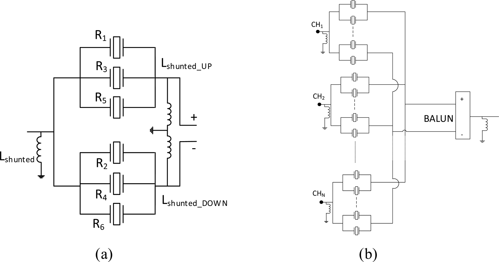
Figure 1(a) shows the transversal topology of a 6th-order filter, whose acoustic resonator-equivalent circuit corresponds to a Butterworth Van Dyke (BVD) [Reference Rosenbaum10]. Analogously, Fig. 1(b) outlines the transversal topology for a multiplexing configuration [Reference Perea-Robles, Mateu and Collado5]. These figures reveal how the resonators are arranged in a transversal manner and all of them are electrically connected from input to output. The filter performance is created through the contribution of each individual path. Basically, resonators are grouped into two kinds of branches: positive and negative, where the resonators in the negative branches need to experience a 180° phase shift. The synthesis procedure to extract the acoustic transversal topology has been fully detailed in [Reference Mateu, Yusuf, Perea-Robles, Collado, Gimenez and Aigner9], but it mainly relies on the extraction of the conventional transversal network [Reference Cameron, Kudsia and Mansour11] in which a set of cross-couplings between input and output is added in order to convert the conventional LC resonators into BVD circuits which reproduce the behavior of piezoelectric crystals and thin film resonators [Reference Rosenbaum10]. The way these cross-couplings are added, and the nature of the characteristic polynomials offers full flexibility on selecting the electro-acoustic coupling coefficient. Mateu et al. [Reference Mateu, Yusuf, Perea-Robles, Collado, Gimenez and Aigner9] also demonstrate how circuit transformations can be applied to introduce control over other critical parameters on the filter implementation, such as the impedance of the resonators and their resonant frequencies. This allows the synthesis of any filter response, in terms of bandwidth and position of transmission zeros.
(a) Transversal network for a single acoustic filter. (b) Transversal network for a multiplexing filtering function.

Despite the great benefits, the requirement of an unbalanced network attained by the inclusion of an external BALUN at the input or output of the filter might lead to a poor performance of the filter due to, for instance, unbalancing effects [Reference Mateu, Collado and Aigner6].
Transversal topology for N-plexer responses
As per interest of the present study, transversal topologies allow for direct connection of different transversal filters without the inclusion of external matching networks between the standalone filters and without much effect on the individual single channel performance. This allows for the synthesis and design of multiplexer responses just by directly connecting each filter, which has been synthesized as a standalone filter. Figure 1(b) illustrates this concept.
This approach was successfully used for the synthesis and design of a 9-plexer, where each individual filter was formed by six resonators, making a filtering stage with a total of 54 resonators [Reference Perea-Robles, Mateu and Collado5]. The great advantage of this topology is that the out-of-band (OoB) response of the standalone filters behaves as an open circuit or close to it in a wideband range.
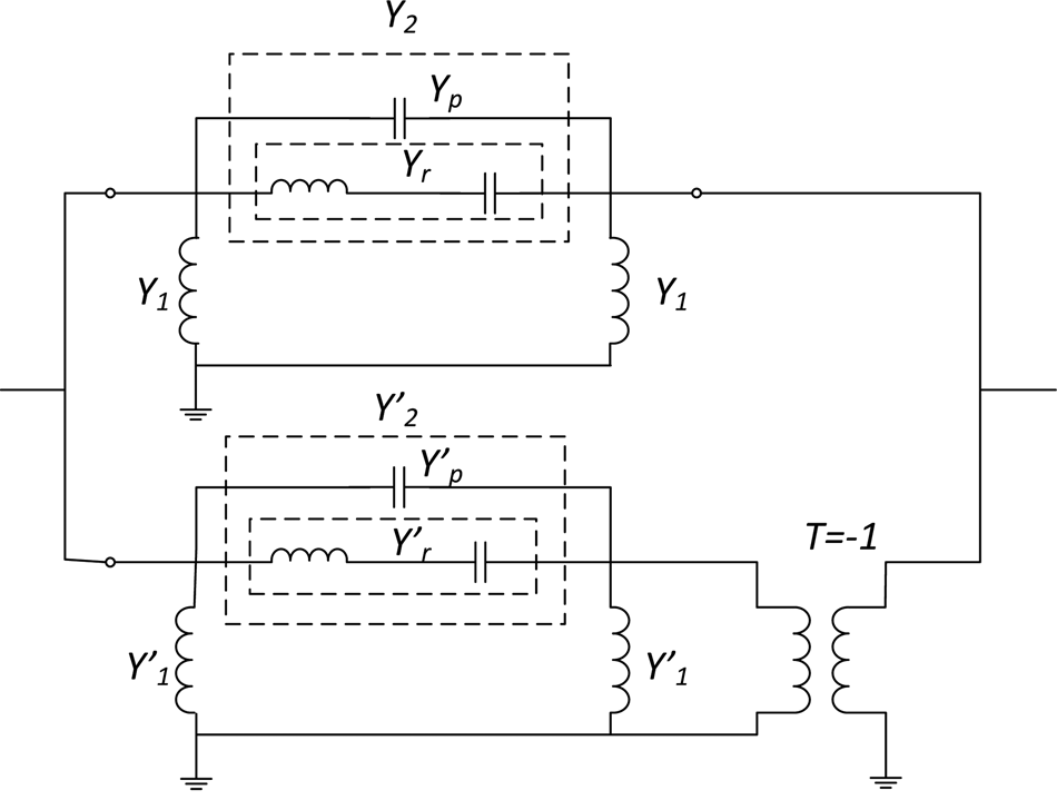
This section illustrates the feasibility of the direct connection of transversal filters by a simple analysis of the circuit shown in Fig. 2. This circuit, and for the sake of simplicity, accounts for a 2nd-order symmetric standalone acoustic transversal filter. For this analysis, the shunt inductances at each branch are defined as admittances Y 1 and $Y_1^{\prime}$ and the BVD resonators as admittances Y 2 and $Y_2^{\prime}$
 . The LC series circuits at the motional branches of the BVD model are defined as admittances Y r and $Y_r^{\prime}$
 and the static capacitances as admittances Y p and $Y_p^{\prime}$
 . The admittance matrices of each branch can be respectively read as:

where the parallel admittances Y p and $Y_p^{\prime}$ are equal at all frequencies and the same happens with Y 1 and $Y_1^{\prime}$
 . In addition, at resonant frequency Y p = −Y 1 and $Y_p^{\prime} = {-}Y_1^{\prime}$
 . Moreover, the admittances forming the motional branches Y r and $Y_r^{\prime}$
 become smaller out of resonance.
Circuital model of a 2nd-order acoustic transversal filter.

Also note that the parameters Y 21 and Y 12 of both matrices differ 180° due to the inherent phase shift in the negative branches of the filter. By considering these assumptions, the OoB admittance matrices can be written as

where ξ and η are phenomenological terms added to account for the effects of the motional branches Y r and $Y_r^{\prime}$ into the OoB response. The overall response is the combination of both matrices which could lead into a phenomenological description as follows:

where δ = 2(Y 1 + Y p), Δ = η + ξ, and ν = η − ξ. Note that this is for the ideal situation, when both static capacitances are equal, and they compensate each other. Whenever this does not happen, another residual parameter appears on ν accounting for the non-compensated error. At this point, it is easy to see that as far as δ, Δ, and ν are equal or close to 0, the better is the filter performance.
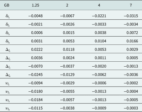
Table 1 outlines the value of the phenomenological parameters δ, Δ, and ν at the central frequency of a 4-plexer of 2nd-order filters (centered at f 1, f 2, f 3, and f 4), all with 80 MHz bandwidth and for different guard bands (GB = 1.25, 2, 4, and 7),whose frequency spacing at the band edges are 15, 60, 180, and 360 MHz, respectively.
Error parameter of the 2nd-order acoustic transversal 4-plexer

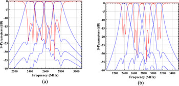
The worst case occurs when the bands are very close (GB = 1.25), because the admittance of the motional branch Y r of each filter is not far enough in frequency to become small, so the accumulated errors at Δ are larger. Note that the value of Δ converges to 0 as the frequency spacing between bands increases. The same occurs with the parameters ν since it accounts for the difference of the errors associated with the positive (ξ) and the negative branches (η). The best performances occur at GB = 2 and GB = 4, where all the parameters of the matrices are almost similar and closest to 0, whose results are outlined in Fig. 3. When the bands have a large separation (GB = 7), the worsening of the responses arise from the different behavior of Y 1 and Y p. Recall that Y p accounts for the static capacitance, synthesized from the added π-network admittance inverters, and Y 1 corresponds to the inductance transformed from the negative capacitance of value −Y p. Then, the equivalences in magnitude only occur at frequencies close to resonant frequencies. Then for large GB, the value of δ diverges from 0.
4-plexer response of (a) GB = 2 and (b) GB = 4.

The following section applies the transversal topology [Reference Perea-Robles, Mateu and Collado5,Reference Mateu, Yusuf, Perea-Robles, Collado, Gimenez and Aigner9] to a CRF configuration of the acoustic resonator. The major asset of this new approach is the possibility of getting rid of the BALUN, by using the properties of the CRF configuration on selecting the phase.
Transversal filters based on acoustically coupled resonator filters
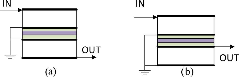
Figures 4(a) and 4(b) outline two CRF sections where two resonators are coupled through a coupling layers configuration (green and purple) [Reference Lakin12,Reference Lakin13]. Black layers are used to indicate the electrodes sandwiching the piezoelectric (white). The thickness and materials forming the coupling layers set the strength of the coupling between resonators. Note as well that for a proper design these need to be set to emulate an admittance inverter. This behaves as a dual-mode resonator. The difference between the CRF sections of Figs. 4(a) and 4(b) relies on the way the ground planes are interconnected and the way the signal is extracted from the dual-mode resonator, this results in a 180° phase shift between the two resonators [Reference Fattinger, Aigner and Nessler14].
Cross-section of a CRF stage, (a) and (b) correspond to a 180° phase difference [Reference Fattinger, Aigner and Nessler14].

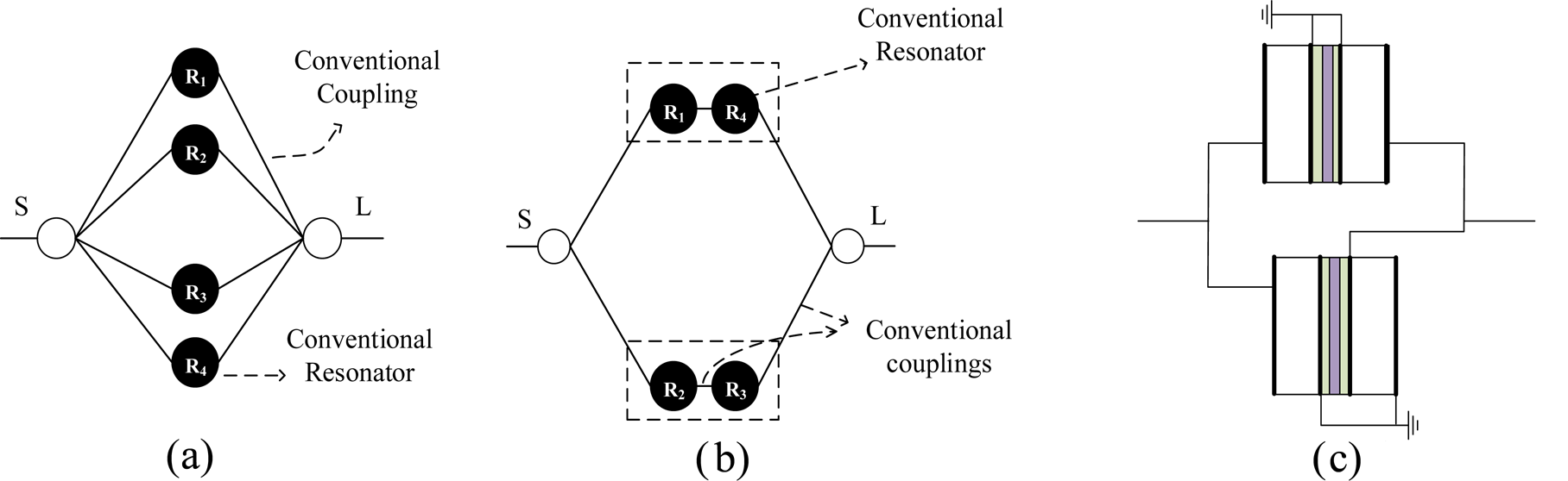
Taking therefore the nature of the CRF configuration the synthesis procedure starts by synthesizing a conventional transversal network as indicated in Fig. 5(a) [Reference Cameron, Kudsia and Mansour11], where each transversal path is formed by a conventional shunted LC resonator sandwiched between two admittance inverters. By considering symmetric responses in frequency, the resonators can be grouped in pairs in such a way that when circuit transformation is applied, the filter results in a transversal topology where each path is formed by two coupled resonators [Reference Cameron, Kudsia and Mansour11], as depicted in Fig. 5(b).
Nodal description of (a) conventional transversal network, (b) dual-mode transversal network, and (c) acoustic CRF transversal configuration.

As it occurs in the conventional transversal network, Fig. 5(b), half of the paths have a negative coupling, which in Fig. 1(a) claimed the need of a BALUN. However, in that case the phase of the signal path can be selected as indicated in Fig. 4 and whose implementation in a transversal filter would correspond to the topology of Fig. 5(c).
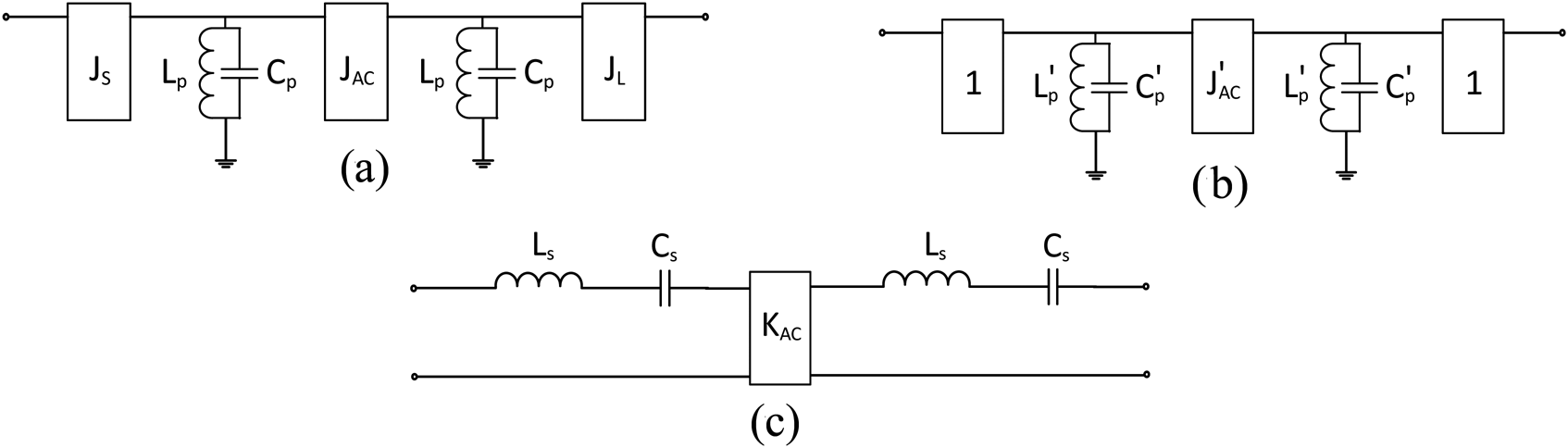
The next step is to transform the network of Fig. 5(b) in CRF configurations similar to the one in Fig. 5(c). To do that, let us consider a single path of the transversal network of Fig. 5(b). The equivalent circuit of each path can be presented as in Fig. 6(a). Node scaling [Reference Cameron, Kudsia and Mansour11] at each path can be applied to obtain unitary coupling between the resonators to the source and load, respectively. This affects the impedance of the resonators now emulated by $L_p^{\prime}$ and $C_p^{\prime}$
 . Although not indicated in Fig. 6(b), one of the unitary couplings might include a 180° phase shift. Note that the coupling between resonators, which is acoustic, is also modified. At this point, the LC resonators are transformed from shunt to series configuration, as in Fig. 6(c). This implies to change the circuit values being now $L_s = C_p^{\prime}$
 and $C_s = L_p^{\prime}$
 . Now, the coupling in the middle is also transformed from an admittance inverter into an impedance inverter whose value is $K_{AC} = 1/J_{AC}^{\prime} \;$
 .
Circuit transformation of synthesized network: (a) LC shunt resonators, (b) LC shunt resonators with normalized input/output coupling, and (c) LC series.

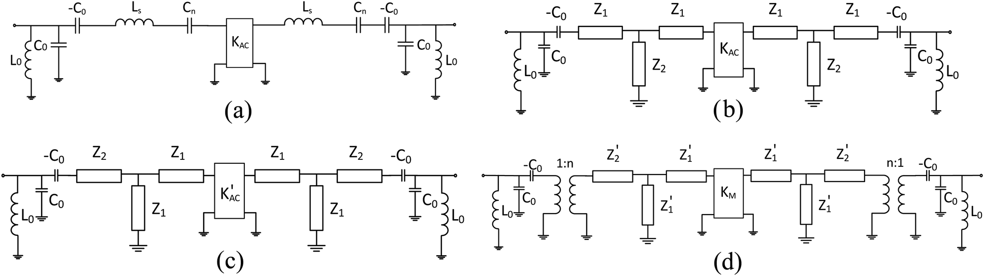
To model the CRF section of Fig. 4, the equivalent circuit needs to include the effect of the electrostatic capacitance, C 0. This can be done as indicated in Fig. 7(a) [Reference Lakin12]. The value of the electrostatic capacitance depends on the electro-acoustic coupling $k_e^2 {\boldsymbol \;}$ and the capacitance accounting for the acoustic resonance C s, which is obtained from the synthesis, as:

Circuital transformations: (a) including C 0 effect, (b) acoustic transmission lines, (c) asymmetrical transmission lines, and (d) Mason model.

The circuit of Fig. 7(a) reveals that this electrostatic capacitance appears as a shunt capacitance at the input (and output) of the resonator and as −C 0 in series with the resonator [Reference Lakin12]. The effect of the negative electrostatic capacitance requires to include a new series capacitance C n to obtain an overall series capacitance C s, as defined by the synthesis. The resonant frequency of the resonators is modified since now there is a new value for the capacitance forming the resonator (being $f_0 = 1/2\pi \sqrt {L_sC_n}$ ). A similar process is done to compensate the shunt electrostatic capacitance, by means of a compensating inductance L 0, see Fig. 7(a). The value of the compensating inductances is calculated as follows: $L_0 = 1/\omega _0^2 C_0$
 . Note that the different frequency dependence impedances from C 0 and L 0 will result in discrepancies between the synthesized and the design filter response whose effect will be more noticeable for wide bandwidths.
Then the series LC resonators are transformed into acoustic transmission lines by applying circuit transformations of common microwave theory [Reference Hong and Lancaster15,Reference Pozar16] giving rise to the circuit Fig. 7(b), where Z 2 corresponds to the impedance at the input of the electro-acoustic transformer in the Mason model and Z 1 to the impedances facing the acoustic boundaries, such as electrodes, Bragg mirror or even air [Reference Lakin12]:

In (5), Z p is the characteristic impedance of the piezoelectric material, which is defined by the area of the device, the propagation velocity v p and density ρ of the material. β is the propagation constant and d is the thickness of the piezoelectric plate which can be directly calculated through v p and the resonant frequency f 0 as d = v p/2f 0 [Reference Mason17].
Although this circuit is formed by transmission lines, it is not representing the circuit of an acoustic CRF, note that the transmission lines are symmetric and the acoustic impedances Z 1, which are the impedances facing the electrodes or reflectors in the Mason model, are connected to the electrical part, thereby facing the electrostatic capacitance. At this point, impedance (node) scaling is applied to go to an asymmetric transmission line circuit (Fig. 7(c)). The impedances are reduced by a factor of 4 [Reference Perea-Robles, Mateu, Collado and Aigner18]. The last step is to add the electro-acoustic transformer to achieve the actual Mason model, which implies that both, the impedance of the resonators and the acoustic coupling are scaled by the turn ratio of the transformer (Fig. 7(d)) [Reference Perea-Robles, Mateu, Collado and Aigner18].
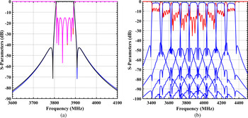
The procedure above has been used to synthesize the transversal network based on CRF resonators for the case of a filter centered at 3.85 GHz and 80 MHz bandwidth. The filter response considering the full distributed model of Fig. 7(d) for each path of the transversal network is outlined in Fig. 8(a), in black and magenta. The results perfectly overlap the synthesized response, indicated in blue and red. Now the overall resulting network does not need any BALUN since the required 180° can be obtained by the way the input or output ports are connected, as indicated in Fig. 5(c) [Reference Fattinger, Aigner and Nessler14].
Performance of acoustic transversal CRF topology: (a) comparison acoustic transversal CRF and BAW transversal with ideal BALUN and (b) acoustic transversal CRF 9-plexer.

Before moving to the design of a multiplexer configuration using such an approach, the effects of the losses are carefully evaluated for the circuit configuration of Fig. 7, where in addition to the limited Q of the acoustic resonators, the losses of the always existing input and output compensating inductances are also considered.
Evaluation of the losses in acoustic transversal CRF
The effect of the losses in electro-acoustic devices may be adequately described by a viscous damping [Reference Rosenbaum10, Reference Auld19]. If we only consider the wave propagation in the longitudinal direction (piston mode), the impedance's equations in (5) can be modified and transformed into their hyperbolic form as

where α is the attenuation factor and is given by

with η 44 and c 44 being the viscosity and elastic constants, respectively, in the longitudinal direction. However, in the CRF configuration depicted in Fig. 7(d), there exists another source of electrical losses, the compensating inductances (L 0), whose value depends on the FBW of the filter and the electro-acoustic coupling (4) and has a finite quality factor (QL = 30 in this analysis).
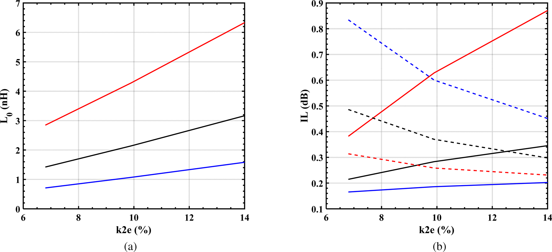
Taking these effects under consideration, Fig. 9 shows the evolution of the compensating inductance and the insertion losses of the filter as a function of the electro-acoustic coupling and for three different FBWs (6%, 12%, and 24%) for a CRF transversal filter operating at 3.85 GHz. As depicted in Fig. 9(a), the compensating inductances increases with the electro-acoustic coupling and decreases for wider bandwidths. The inductance values directly affect their losses whose effect on the insertion losses is outlined, in dashed lines in Fig. 9(b), revealing that the effects of the inductance are more harmful for wide bandwidths and small electro-acoustic couplings.
Evolution of (a) the compensating inductance and (b) the insertion losses due to viscous damping (bold) and inductance size (dash) over the electro-acoustic coupling coefficient for FBWs of (red) 6%, (black) 12%, and (blue) 24%.

Along with the losses coming from the compensating inductances, Fig. 9(b) also depicts the insertion losses due to the acoustic propagation occurring in the piezoelectric material. These results reveal an opposite behavior and confirm that the acoustic losses increase for larger electro-acoustic coupling and decreases for larger bandwidths.
Example of a CRF 9-plexer
This final subsection uses the flexibility of the transversal topology based on CRF to create multiplexing structures as done in [Reference Perea-Robles, Mateu and Collado5]. Figure 8(b) shows the performance of a 9-plexer based on acoustic transversal CRF. The bandwidth of the filters is set to 80 MHz. The spacing between central frequencies of each individual filter is 100 MHz. Note that, as previously done in [Reference Perea-Robles, Mateu and Collado5], the filters are designed as standalone, and they are simply connected without the inclusion of matching networks or without any optimization of the response. Losses are also included.
Conclusion
This paper defined the development of multiplexing configurations based on transversal topologies of acoustic filters. Two types of acoustic resonator configurations are considered, the BAW (and/or SAW) configurations whose equivalent circuit model is defined by a BVD, and the CRF configuration which results in a dual-mode resonator response. The synthesis procedure for the two types of resonators demonstrates the ability of using transversal networks to create complex filtering solutions. The examples shown in this study account for all the distributed effects of the resonators and demonstrate to be useful for multiplexers covering a wide range of frequencies and with very near bands without the need of applying any additional process to interconnect the different filters composing the whole structure. Additional advantage of the configuration based on CRF is the possibility to remove the BALUN section existing in other acoustic transversal solutions [Reference Perea-Robles, Mateu and Collado5,Reference Mateu, Yusuf, Perea-Robles, Collado, Gimenez and Aigner9].
Acknowledgement
This study has been supported by the Spanish Government through grants TEC2017-84817-C2-2-R, TEC2017-88343-C4-2-R, and by Generalitat de Catalunya through 2017 SGR 813.
 Rafael Perea-Robles received the B.S. and M.S. degrees in telecommunication engineering from the Universitat Politècnica de Catalunya (UPC), Barcelona, Spain, in 2016 and 2017, respectively. Since 2017, he is pursuing PhD in the Components and Systems for Communications (CSC) research group which is associated with the Department of Signal Theory and Communications, UPC. His thesis is based on the development of synthesis techniques and novel topologies for electro-acoustic filters for communication systems. His research interests include the synthesis and design of filters and multiplexers based on electro-acoustic technology as well as the characterization of their inherent nonlinear behavior.
 Jordi Mateu (A'02–M'04–SM'10) received the Telecommunication Engineering degree and Ph.D. degree from the Universitat Politècnica de Catalunya (UPC), Barcelona, Spain, in 1999 and 2003, respectively. Since 2007, he has been with the Department of Signal Theory and Communications, UPC, where he is currently an associate professor. He is also with the Center Tecnologic de Telecomunicacions de Catalunya (CTTC), Castelldefels, Spain, as an external senior research associate. He also possesses over six years of experience outside academia as engineer, researcher, and manager with Gillette, U.K., Superconductor Technologies Inc., Santa Barbara, CA, USA, CTTC, and the Massachusetts Institute of Technology, Cambridge, MA, USA, including over three years with the National Institute of Standards and Technology (NIST), Boulder, CO, USA.
 Carlos Collado received the telecommunication engineering degree and Ph.D. degree from the UPC, Barcelona, Spain, in 1995 and 2001, respectively. He also holds an M.S. in biomedical engineering (2002). Since April 2005, he has been an associate professor with UPC. In 2004, he was a visiting researcher with the University of California Irvine. During the academic course 2009–2010 he was on Sabbatical at the National Institute of Standards and Technologies (NIST), Boulder, CO, USA. His primary research interests include microwave devices and systems, study of efficient methods for the analysis of nonlinear effects in communication systems, and characterization of the nonlinear behavior of electro-acoustic devices.
 Yazid Yusuf received the B.S. degree in electrical engineering from Jordan University of Science and Technology, Jordan, in 2005, and an M.S. and Ph.D. degrees in electrical engineering and computer science at the University of Central Florida (UCF), Orlando in 2008 and 2011, respectively. He worked as a postdoctoral researcher at the University of Wisconsin-Madison, before joining the Bulk Acoustic Wave (BAW) R&D group at Qorvo in 2012. He is currently a principal engineer and senior member of the technical staff. His interests include the physics and design of acoustic devices, and the synthesis and design of multiplexer networks and filters.
 Alfred Gimenez was born in Lleida, Spain, in 1988. He received an M.S. degree in electrical engineering and Ph.D. degree (cum laude) from the Universitat Autònoma de Barcelona (UAB), Barcelona, Spain, in 2013 and 2016, respectively. His thesis concerned the development of synthesis methodologies for filters and multiplexer designs based on bulk acoustic wave (BAW) devices. In 2012, he joined the Antenna and Microwave System Group, UAB, where he was involved in research projects, including computer-aided design of microwave filters with BAW and SAW devices. In 2016 he joined the BAW R&D Group at Qorvo Inc., Apopka, FL, USA, where he is currently involved in technology development of new generation RF acoustic wave devices. During his career at Qorvo, he has also been involved in various commercial RF modules using BAW filters. His current research interests include design and synthesis of RF filters and multiplexers, BAW and SAW devices, and electrical design automation.
 Robert Aigner received a Ph.D. degree from Munich Technical University in 1996 for research on micromachined chemical sensors. He was a visiting scientist at UC Berkeley Sensors and Actuators Center BSAC in 1996 where he worked on system design for inertial sensors. He joined the MEMS research group at Siemens Corporate Technology in 1997. Between 1999 and 2005 he was director of a MEMS R&D department at Infineon Technologies and worked on a variety of MEMS devices including Automotive MEMS and RF-MEMS. The team he built and directed became pioneers in commercializing Bulk-Acoustic-Wave (BAW) technology. In 2006 he joined TriQuint in Apopka/Florida to establish BAW. TriQuint merged into Qorvo in early 2015. As head of R&D for acoustic filter technology at Qorvo his focus is on driving technology innovations. He has served in several European committees for Microsystem Technology and was nominated as MEMS-expert for European Commission. He participated in the technical program committee of IEEE UFFC and serves as reviewer for JMEMS, Applied Physics Letters, and other journals. He has more than 120 patents in the field of BAW, SAW, and MEMS granted on his name, has published more than 130 articles, and contributed chapters to four text books.