1. INTRODUCTION
As the application area of GPS continues to expand and electronic information technology makes remarkable progress, traditional GPS signals can no longer meet the increasing demand for new GNSS applications. GPS and Galileo have initiated research on new GNSS signals since the late 1990s. Many new features such as BOC modulation have been adopted into modern GPS/Galileo signals after decades of development (Betz, Reference Betz1999).
New GNSS signals tend to separate pilot and data components. The power and phase relationship between components is much more flexible and the number of signals that have to be transmitted on the same carrier is increased. To maximise the efficiency of the high power amplifiers, it is preferred that the system operate at saturation of its nonlinear region (Spilker, Reference Spilker and Richard1998). Otherwise it leads to amplitude-to-amplitude modulation (AM/AM) and amplitude-to-phase modulation (AM/PM) distortions when the envelope of the composite signal is not constant. Thus multiplexing multiple signals on the same carrier into a constant envelope is one of the key problems in generating modern GNSS signals.
The essence of constant envelope modulation is captured by phase modulation. Any constant envelope modulation of complex signals can be described as a phase function with variable t. The Phase-Optimised Constant-Envelope Transmission (POCET) modulation was first proposed by Dafesh (Reference Dafesh and Cahn2009) as a unified numerical algorithm that searches the minimum combining loss for any number of binary navigation signals. The principle is to search for the optimum phase angles that maximise the combined efficiency for any given binary navigation signal constraints. The POCET method efficiently solved the problem on the GPS L1 band and is expected to be used on later versions of GPS III satellites to improve the transmitter efficiency (Stansell, Reference Stansell, Hudnut and Keegan2010). The POCET transmitter of modern GPS signals has been verified by hardware-in-loop simulations (Dafesh, Reference Dafesh and Cahn2011). Further studies show that it is feasible to combine signals at different carrier frequencies into a constant envelope signal by POCET (Dafesh, Bow, Reference Dafesh, Bow, Fan and Hsu2011). The result reduces the number of HPAs for different frequencies, thus greatly simplifying the payload design on satellites.
Compass Regional Navigation System use QPSK modulation and plan to provide services similar to GPS C/A and P(Y) code in the near future. The Compass Global Navigation System will update its signals based on the signal evolution of GPS and Galileo. The global signals must be backward compatible with the regional signals to maintain open services (OS), thus reducing the risk for Compass modernisation. The result is that signals transmitted on the same carrier would be much more complex with various new features.
For backward compatibility of Compass B1 signals, BPSK (2) and MBOC (6, 1, 1/11) with 14·322 MHz centre frequency difference must be multiplexed. A complex binary offset carrier is used to implement the carrier difference. For B3 signals, a BOC (15, 2·5) signal is added to the existing QPSK (10) signals. These multiplexing problems are modelled and evaluated by the POCET method.
This paper is organised as follows. In Section 2, a numerical algorithm that employs the POCET principle is given. In Section 3, a signal model developed for the Compass B1 band is specified. In Section 4, the Interplex modulation is compared with POCET for the Compass B3 band. Modulation quality analysis in the presence of finite DA word-length effects and simulations that illustrate the efficiency of the proposed solution on the B1 band are given in Section 5. Section 6 presents the summary for this paper.
2. PHASE-OPTIMISED CONSTANT-ENVELOPE TRANSMISSION ALGORITHM
2.1. POCET Methodology
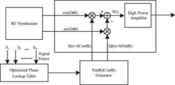
The POCET approach modulates the carrier phase directly by angles pre-computed according to the input binary signals and produces a constant envelope signal that combines all the signals. The principles were first introduced by Dafesh (Reference Dafesh and Cahn2009). N binary pseudorandom noise code signals have 2N signal vectors for the POCET modulator. For every signal vector, POCET has an optimised transmission angle θ i (0⩽i⩽2N−1) and modulates the carrier phase by θ i. Figure 1 shows the quadrature implementation of POCET (Dafesh, Reference Dafesh and Cahn2009).
Quadrature implementation of POCET modulator (Dafesh, Reference Dafesh and Cahn2009).

Two assumptions are made to derive the amplitude and phase relationship between signal components from θ i:
• N spreading pseudorandom codes are uncorrelated
• Every pseudorandom code is perfectly balanced, which means 0 and 1 occur both with 50% probability.
Well designed GNSS pseudorandom codes satisfy the assumptions with negligible errors. It can be concluded that 2N possible signal vectors occur with equal probability. If the receiver correlates the navigation signal with the k th pseudorandom code, the average correlator output is:
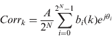
where b i(k) is the k th signal component in the i th signal vector, A is amplitude of the envelope. For BPSK modulation, b i(k)=±1. GNSS receivers mainly concern the phase/amplitude relationship between signal components. The phase relationship φ mn between signal m and signal n can be expressed as:


The total power of the N signals is the efficient power that can be measured by the receivers. The power efficiency η of the constant envelope signal is:
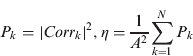
where P k is the power of the k th signal. The amplitude relationship between signal m and signal n can be expressed as:

To reduce the computational and storage complexity, the symmetry between 2N signal vectors can be used. If two vectors are complementary, the difference of transmit angles should be ±180°.
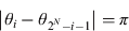

From equations (2)∼(5), rotating the constellation by θ i (0⩽i⩽2N−1) does not change the phase/amplitude relationship between signal components or the combining efficiency, thus the transmit angle for the first signal vector can be assumed to be zero.

With these constraints, the parameters required to generate the constant-envelope signal can be reduced to K=2N−1 angles. The design routine of the POCET model is a typical non-linear optimisation problem that maximises the power efficiency η with multiple constraints.
2.2. Modified Optimisation Model
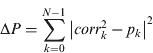
The POCET model is a nonlinear programming problem with a single objective function. A penalty method was used to convert the constrained optimisation into an equivalent unconstrained search (Dafesh, Reference Dafesh and Cahn2009). The amplitude factor A is merged into the unconstrained problem for numerical optimisation. From equations (1)∼(5), the power efficiency and phase/amplitude relationship can be calculated only from θ i and are independent of A. To eliminate the term of amplitude in the optimisation problem, the modified correlation value corr k and expected signal power p k are defined as follows:
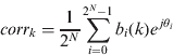
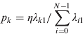
The combining efficiency can be expressed as the sum of p k, which represents the power percentage that the k th signal should have. The total power control error ΔP is:
The phase control error Δφ is the sum of all phase errors between signals that have a constant phase relationship:
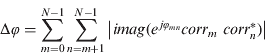
Equation (12) takes the absolute value of the imaginary part that represents the phase error, which results in a 180° ambiguity. This ambiguity can be solved by analysing the phase relationship calculated from the optimum solution. If the angle constraint is Φ, but the angle generated between two signals is Φ+180°, then one of the signals can be reversed by 180° before the POCET modulation to solve the ambiguity. Since there are K=2N−1 independent angles, the optimisation problem would have 2K ambiguous solutions that converge to the optimum η, which benefits the numerical search routine.
The combining efficiency η, phase error Δφ and power error ΔP are combined into a single objective function. The modified unconstrained optimisation problem is:

where μ a and μ b are positive penalty factors. Broyden-Fletcher-Goldfarb-Shanno's (BFGS) Quasi-Newton method with a cubic line search procedure is used for numerical optimisation. The search strategy from Dafesh (Reference Dafesh and Cahn2009) is adopted to search the global optimum solution.
3. MULTIPLEXING MODEL OF COMPASS B1 BAND
The B1 OS signal for the Compass regional system uses BPSK (2) modulation at 1561·098 MHz (Gao, Reference Gao2008). The global Compass signal will adopt MBOC modulated OS signals and BOC (14, 2) modulated Authorized Service (AS) signals at 1575·42 MHz which are compatible with GPS/Galileo signals (UN, 2010).
In this paper, the AS signals are assumed to be transmitted from a separate aperture and the multiplexing problem on the B1 band is how to combine BPSK (2) and MBOC signal with a centre frequency difference of 14·322 MHz.
3.1. MBOC Implementation
Compass baseline options use MBOC(6, 1, 1/11) as global B1 OS signals (UN, 2010), which are a mixture of BOC(1, 1) and BOC(6, 1) with a power ratio of 10:1. MBOC modulation has three different implementations:
• Composite BOC (CBOC) modulation linearly combines BOC(1, 1) and BOC(6, 1) sub-carriers. The waveform has four different levels (Avila-Rodriguez, Reference Avila-Rodriguez, Hein, Wallner, Issler, Ries, Lestarquit, Latour, Godet, Bastide, Pratt and Owen2007). Consequently this requires the receiver to generate a local replica that also has four levels and leads to greater combining difficulty with other signals.
• Time Multiplexed BOC (TMBOC) uses a time-multiplexing of BOC (1, 1) and BOC (6, 1). The waveform has only two levels, thus it can be processed by only a 1-bit replica (Hoult, Reference Hoult, Aguado and Xia2008). TMBOC has only two binary signal components that represent the pilot and data signal respectively. This makes it much easier to be combined with other signals.
• Quadrature Multiplexed BOC modulates BOC(1, 1) and BOC(6, 1) on quadrature carrier phases (Yao, Reference Yao, Lu and Feng2010). The receiver architecture is simple but there are at least three binary signals if data and pilot components are separated.
TMBOC has the least number of components and is fully interoperable with GPS L1C signals. In this paper TMBOC is chosen as the candidate for the Compass B1 signal. The pilot signal S mboc−p(t) and data signal S mboc−d(t) are modulated on the same carrier phase with power ratio of 3:1.
3.2. B1 POCET Model and Solution
The global OS signal has the same carrier frequency as the GPS L1. The centre frequency of the regional OS signal is 14·322 MHz lower than the GPS L1. Binary complex subcarrier SC(t) is proposed to implement this frequency shift:
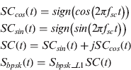
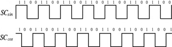
where f sc=14·322 MHz is the frequency of the sub-carrier. S bpsk_L1 is the regional BPSK (2) signal modulated on the L1 carrier, S bpsk is the regional BPSK(2) signal, SC cos(t) and SC sin(t) are two separate binary signals with four possible combinations. In an interval of BPSK(2) spreading code period T c, SCcos and SC sin both have seven periods and SC cos(t) equals SC sin(t) advanced by a quarter of its period. The odds of the four combinations are precisely 25% and satisfy the assumptions of POCET. The sub-carriers are depicted in Figure 2.
SCsin/SCcos waveforms in Tc.

The power ratio of the harmonics of the complex sub-carrier is in Table 1 (Lestarquit, Reference Lestarquit, Artaud and Issler2008). The harmonics at −f sc have 81·05% of the total power. Harmonics at f sc have no power and thus no mirror interference is produced. The interference with the highest power is at +3f sc=42·966 MHz. After filtering on satellites the interference will be eliminated and will have negligible effect on other radio systems.
Power ratio of Harmonics (%).

BPSK signals modulated by the complex sub-carrier can be expressed as a QPSK modulation with equal power on in-phase and quadrature phase signals. The complex binary sub-carrier is a fine approximation of the linear single sideband carrier.
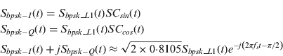
The four signals that need to be multiplexed are S bpsk−I, Sbpsk−Q, Smboc−p and S mboc−d. Smboc−p and S mboc−d are pilot and data components of TMBOC signal. There is no phase constraint between S bpsk−I and S mboc−p. As is explained above, the phase ambiguity can be resolved by reversing the sign of the input signals.
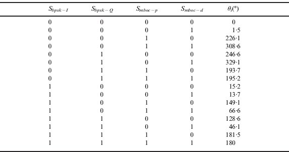
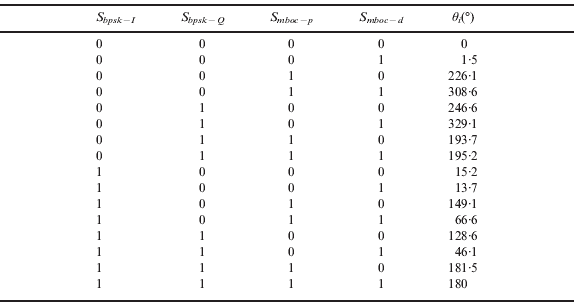
The power constraints between the BPSK and TMBOC signals are set as the ratio between the GPS C/A and L1C signals. If the BPSK (2) power is normalised at 0 dB, the power of TMBOC-Pilot and TMBOC-Data should be 0·25 dB and −4·52 dB respectively. The power of S bpsk is the power sum of S bpsk−I and S bpsk−Q multiplied by the power ratio of the fundamental harmonics at −f sc. The power and phase constraints are summarised in Table 2. The constraints are modelled by POCET. In all there are 16 transmitting angles. The optimum solution is shown in Table 3.
Power/Phase constraints for Compass B1 signals.

Optimum transmit angles for B1 band.
3.3. Power Efficiency Evaluation
To evaluate the power efficiency of the optimum POCET solution, Interplex modulation and Major Voting are used to multiplex B1 signals. The result from Table 3 is evaluated by equation (4). The power efficiency of POCET is:

Any two signal components must be in-phase or in phase quadrature in Interplex modulation (Butman, Reference Butman and Timor1972). Note that the S bpsk−I /S bpsk−Q components are in quadrature phase with the same power and the S mboc−d /S mboc−p components are in-phase, thus it is the same that any of the S bpsk−I /S bpsk−Q are in-phase with S mboc−d. The baseband B1 signal multiplexed by Interplex is:
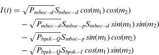
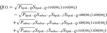
where m 1 and m 2 are phase parameters determined by power constraints:
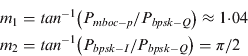
From equation (16)∼(18), the power efficiency of Interplex modulation is:

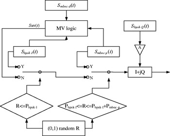
The Traditional Major Voting algorithm can only multiplex an even number of signals with equal power. Signals with different power should be multiplexed with Interlace technology (Fan, Reference Fan, Lin, Wang and Dafesh2008). If there are four signals, three of them are combined into a BPSK signal with interlaced major voting. Then it is transmitted with the fourth signal as a QPSK modulation. Since S bpsk−I and S bpsk−Q are in quadrature phase, one of them must be the fourth signal. The combining efficiency is maximised if the signal with the smallest power is not interlaced. The configuration for Major Voting is shown in Figure 3. The optimum efficiency is:

Major Voting to combine 4 signals on B1.

It can be seen that the combining loss of POCET is 2·0 dB less than Interplex and 0·7 dB less than Major Voting.
3.4. Approximate POCET Signal Model
If the optimised angles are implemented in the POCET modulator, the correlator output and the relative power/phase relationships between S bpsk−I and other components are listed in Table 4.
Optimum power/phase relationship for B1 signals.

It is interesting that even though no phase constraint is made between S bpsk−I and S mboc−p, the optimum solution shows that they are still in phase quadrature. From equation (15), the baseband signal generated from POCET modulator can be approximated as:
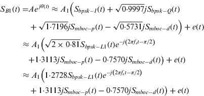
where A 1 is the equivalent amplitude of S bpsk−I, e(t) is the inter-modulation signal that makes the envelope of the baseband signal constant. The approximate model shows that the regional BPSK (2) signal and global TMBOC signal are embedded into the baseband signal and comply with the power/phase constraints.
4. MULTIPLEXING MODEL OF COMPASS B3 BAND
To maintain backward compatibility on the Compass B3 band, satellites should transmit regional QPSK (10) and global BOC (15, 2·5) signals simultaneously. The power and phase constraints for the B3 band are summarised in Table 5. No special phase constraints between BOC (15, 2·5) and QPSK (10) are assumed.
Power/Phase constraints for B3 signals.

The power relationship β and phase relationship γ between BOC (15, 2·5) and QPSK-I is designable. From equations (6)∼(8), there are only three signal components and three independent angles to be optimised. Interplex modulation is widely used to combine three signals. The combining loss for POCET and Interplex modulation is compared in Table 6.
Comparison of power efficiency between POCET and Interplex for B3 Band.

For both the POCET and Interplex modulation, the power efficiency decreases as β increases. The two methods actually have the same performance. It is concluded that Interplex modulation is the optimum multiplexing solution for the Compass B3 band.
5. POCET MODULATOR VALIDATION
Since Interplex modulation is widely discussed (Dafesh, Reference Dafesh, Cooper and Partridge2000), only B1 signals that adopt the POCET modulator are analysed here.
5.1. Signal Quality in the Presence of Finite DA Word-length
Most combining methods need accurate signal computation. Digital technology provides great flexibility for signal manipulation and has become the first choice for modern GNSS signal generation. The total correlation loss of GPS C/A and L2C code is less than 0·6 dB and will be improved to 0·3 dB on GPS III satellites. The quadrature or in-phase error should be within 100 milliradians for all GPS signals (GPS Wing, 2010). Baseband modulation should provide signal quality much higher than these requirements.
The accuracy of the sine and cosine waveforms in Figure 1 is determined by DA word-length. If the DA word-length is limited, the sine and cosine wave cannot precisely implement the optimum transmit angle and distort the power and phase relationship. For a specified word-length M, the sine and cosine waveforms are approximated by:


where [.] is the round function. The relative power error dλ mn and phase error dφ mn are defined as:


where angle(.) is the phase angle function. dλ mn and dφ mn are used for modulation quality evaluation. The quality analysis for the four signal components on B1 band is summarised in Table 7. The result shows that with an ideal DA of 10 bit, the relative phase error is less than 0·1°. Receivers seldom use the relative power relationship between the signal components and the relative power error is sufficient for most applications.
Signal quality for different DA word-length on B1 band.

5.2. Signal Model Validation
A POCET modulator and receivers tracking BPSK and TMBOC (6, 1, 1/11) signals are simulated. The power level for each signal component is measured and compared with the approximate signal model. The Power Spectrum Density (PSD) is estimated by periodogram algorithm.
5.2.1. Simulation Setup
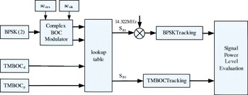
The architecture of the simulation environment is given in Figure 4. The first branch of S B1(t) is up converted by 14·322 MHz and tracked by a BPSK (2) receiver. The second branch is tracked by a TMBOC (6, 1, 1/11) receiver.
Simulation architecture for B1 signal generation and tracking.

The simulated carrier-to-noise ratio was 45 dBHz. The correlations for all receivers were averaged over 10 s to obtain an accurate estimate of the signal amplitude and correlation function. The PSD of S B1(t) was simulated by generating noiseless signals with random spreading codes at the complex sampling rate of 171·864 MHz and averaging the results of periodogram algorithm through 1000 Monte Carlo runs. The spectrum measurement was corrected by a function of frequency as follows to compensate for the sampling effect (Dafesh, Reference Dafesh and Cahn2009).

The PSD computation aliases beyond 85·932 MHz. It is expected that the transmission bandwidth is less than 40 MHz and frequencies outside of this bandwidth are cut off by satellite filters. No special filtering or Doppler effects were considered in the simulation.
5.2.2. PSD Analysis and Tracking Results
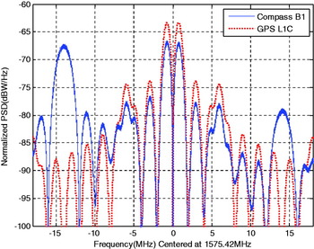
The normalised PSD is compared with GPS L1C in Figure 5. The signal power for Compass B1 signals and GPS L1C is assumed as 1W. The results are plotted with the zero frequency located at the centre frequency of L1C. The BPSK component is located at −14·322 MHz in Figure 5. The TMBOC(6, 1, 1/11) component in the Compass B1 signal has the same PSD shape as the L1C signal, but the power level is lower since the power of the B1 carrier is shared between the BPSK and TMBOC components.
Normalised PSD comparison between GPS L1C and Compass B1.

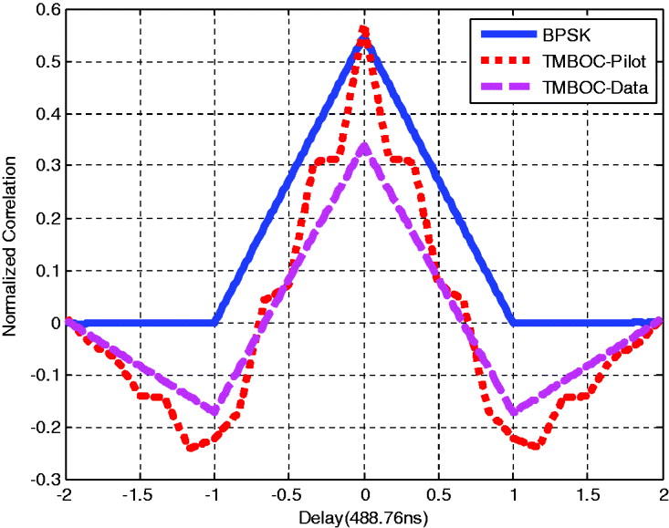
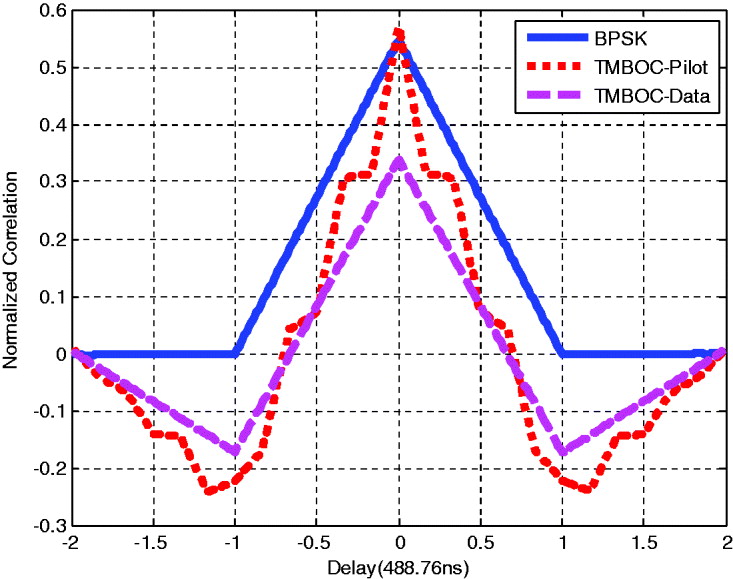
The normalised cross correlation between S B1(t) and the three local replicas of different components are depicted in Figure 6. The simulation results and analysis are summarised as follows:
• The POCET modulator combines the BPSK (2) and TMBOC (6, 1, 1/11) signals into a constant envelope signal.
• The correlation peaks are measured as 0·554/0·560/0·330 respectively. If the BPSK power is normalised to 0dBW, the relative powers of TMBOC-Pilot and TMBOC-Data are 0·1 dB and −4·5 dB. The power error is introduced by the imperfection of the simulated pseudorandom codes.
Normalised correlation function between BPSK/TMBOC-Pilot/TMBOC-Data replicas and SB1.
An undesired interference component shows up at 14·322 MHz in Figure 5. Its power is 12 dB lower than the BPSK component and is compatible with other GNSS signals.
6. CONCLUSIONS
In this paper we examined the POCET method for the future Compass signals. A binary complex subcarrier was adopted to implement the frequency shift for the Compass B1 band. The global TMBOC and regional BPSK signals were combined with 1·0 dB loss, which is 0·7 dB less than the MV technique. For the B3 band, the POCET method is equivalent to Interplex modulation.
In addition to the efficiency, signal quality in the presence of finite word-length was evaluated for the B1 band. With 10bit DA converters, the phase error is controlled to less than 0·1 degrees and the power error has equivalently more than 20 dB attenuation. Both of these are sufficient for navigation applications.
This paper represents an initial exploration into signal combining for the Compass navigation system. The results show the possibility to maintain backward compatibility of regional Compass open services. The impact on satellite payload will be further evaluated.
ACKNOWLEDGMENTS
The authors would like to express their appreciation to the China Satellite Navigation Office (CSNO) for funding this research. The author acknowledges the many useful inputs and insights from the Compass Signal Design Team.