Nomenclature
-
 ${R_{Hex}}$
-
circumradius of position hexagon
-
$d$
-
circumscribed circle diameter of the single hexagon module
-
$r$
-
gap distance between two modules on the plane projection
-
$n$
-
number of module layers
-
${P_{Mi}}$
-
geometric centre of the module i
-
$P_i^1$
-
node 1 of the module i
-
$P_{Mi}^j$
-
geometric centre of the mounting surface of the module i
-
$P_i^{j1}$
-
first connecting node of the
$i$
and j module -
$V_{ij}^k$
-
virtual assembly point between the module
${\rm{i\;}}$
and module
$j$
-
$\boldsymbol{{s}}$
-
principal part of the screw about the assembly error
-
${\boldsymbol{{s}}_0}$
-
subpart
${\boldsymbol{{s}}_0}$
of the screw about the assembly error -
${e^{\hat \xi \theta }}$
-
exponential product of rotation
-
${e^{\hat \xi d}}$
-
exponential product of movement
-
${g_{ab}}\!\left( 0 \right)$
-
ideal position of the assembly module
-
${g_{ab}}\!\left( \theta \right)$
-
actual position of the assembly module
-
${P_i}$
-
deformed data point set
-
${Q_i}$
-
ideal data point set
-
$\boldsymbol{{R}}$
-
3 × 3 rotation matrix
-
$\boldsymbol{{T}}$
-
3 × 1 translation vector
-
$l_1^N$
-
length between two points of the new moving platform and the static platform
-
$\Delta {\rm{l}}$
-
length change of the actuator


Abbreviations
- RMS
-
root-mean-square
- SVD
-
singular value decomposition
1.0 Introduction
Design and construction of ultra-large-aperture antennas are limited by the maximum carriage size and load of the launch vehicle. With the rapid development of aerospace technology, such as the deep space exploration, communication and manned spaceflight, the requirements for high-performance antennas are becoming more and more urgent. It is well known that the aperture and surface accuracy are important factors affecting the gain and directivity of the antennas. To achieve the better performances, the antennas are becoming larger and higher in aperture and surface accuracy, respectively [Reference Puig, Barton and Rando1–Reference Meshkovsky, Sdobnikov and Kisanov4]. And the limitations of the launch vehicle’s size and payload can be broken through by the on-orbit assembly technology. Therefore, the on-orbit assembly is an important path to realise the ultra-large-aperture antennas in the future.
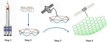
There are many different types of space antennas, such as solid surface deployable antennas [Reference Wu, Li and Li5, Reference Huang, Guan, Pan and Xu6], inflatable antennas [Reference Shinde and Upadhyay7] and cable-net antennas [Reference Li, Tang and Zhang8–Reference Tang, Li, Liu and Wang10]. Although the solid surface deployable antennas can achieve high surface accuracy, the apertures are small. Another interesting type is the inflatable antenna, which is made by the special material with low density. However, the thermal environment and material characteristics will lead to poor surface accuracy, which limit the application of inflatable antennas [Reference Liu, Qiu, Li and Yang11]. The cable-net antennas have the advantages of light weight and small folding volume, and can be divided into wrapped rib antennas, hoop truss antennas, radial rib antennas and so on. Currently, some cable-net antennas have been manufactured and launched by different research institutions [Reference Liu, Guo and Liu12–Reference Shen, Lin and Wang15]. There are still difficulties in meeting the requirements for ultra-large-aperture antennas even through the length of antennas is on the order of ten meters. In order to construct the ultra-large-aperture antennas, the concept of modular antennas was proposed based on the on-orbit assembly technology [Reference Wang, Liu, Yang, Cong and Guo16–Reference Izzo, Pettazzi and Ayre18]. The process of modular antennas’ on-orbit assembly is shown in Fig. 1, where the launch vehicle will launch the folded modules into the orbit firstly, and deploy the modules, then the deployed modules are operated and assembled by a satellite manipulator.
The process of on-orbit assembly.

To obtain the high gain and directivity, the large apertures and high surface accuracy are key influencing factors for modular antennas. It can be known that the nodes of a single module must be designed accurately, and the root-mean-square (RMS) error of the reflector is low. Thus, an accurate node design method needs to be researched. Another key point is that the assembly error is an inevitable factor affecting the surface accuracy, and it still needs to explore an analytical method for assembly error. To reduce the assembly error of the modular antennas, the actuators are placed to adjust the positions between the modules. Up to now, different types of deployable module have been designed and analysed by researchers. Huang et al. [Reference Huang, Li and Qi19] designed a single-mobility deployable mechanism with the irregular-shaped triangular prismoid modules, which has the advantage of lacking redundant constraints. Shi et al. [Reference Shi, Guo and Zhang20] proposed a configuration synthesis and structure analysis method based on the graph theory and obtained a series of modules for double-layer loop deployable antenna. In practical engineering applications, the antenna carried by ETS-VIII satellite is a typical modular antenna [Reference Tomyuki, Takashi and Takashi21]. However, those modular antennas need to be assembled on the ground before being launched into space. Also, Guo et al. [Reference Guo, Zhao and Xu22] studied a novel hexagonal profile division method to design the deployable mechanism, which divided the reflector into multiple triangular planes. Then, they proposed a new deployable unit based on the 3RR-3URU tetrahedral symmetrical combination unit. The assembly method and the arrangement of connecting joints were researched [Reference Guo, Zhao and Xu23]. However, the connecting joints consists of many joints, resulting in large assembly errors. In previous work, a variety of module structure design methods have been widely proposed. However, only few attentions have been paid to node design of modular antennas. Moreover, the design precision of nodes is an important factor affecting the surface accuracy of modular antennas. In addition to the nodes position, the assembly errors are also unavoidable factors to decrease the surface accuracy.
One of the main contributions of this work is to propose the module node design method, which considers the assembly gaps between two modules. In order to ensure the mobility of the antenna, a soft connection is designed. Another main contribution is to establish an analytical model of assembly errors, and it lays the technology foundation for surface adjustment. Based on the analytical model, the concept of error ball is proposed to establish the deformation surface with the rotation and displacement assembly errors, which is applied to generate the deformation surface and close to engineering practice. Finally, an adjustment algorithm is proposed to improve the surface accuracy.
This paper is organised as follows. After the related works is introduced in this section, the module node generation method is proposed in Section 2. Furthermore, Section 3 deduces the assembly error analysis, and Section 4 presents the simulation results of the model. Finally, the conclusions are drawn in Section 5.
2.0 Module nodes generation method
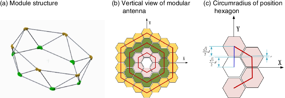
Because the actuators and joints are installed between two modules, assembly gaps are unavoidable. The design of module nodes needs to consider the assembly gap. A module consists of 12 nodes and 24 rods is presented, as is shown in Fig. 2(a).
Composition of the Modular antenna.

The vertical view of the modular antenna is shown in Fig. 2(b). The red regular hexagon connects the geometric centre points of every module, which called the position hexagon. In the projection plane of the vertical view, the circumradius of position hexagon is
 \begin{align}{R_{Hex}} = n\sqrt 3 d + nr\end{align}
where
 $d$
is the inscribed circle diameter of the single module on the projection plane,
 $r$
is the gap distance between the two modules on the plane projection and
 $n$
is the number of module layers, as shown in Fig. 2(c), respectively. It should be noted that the formula of definite proportion and separated points can be applied to obtain the position of geometric centre point of each module on the projection plane because the number of modules placed on each side of the position hexagon is equal.
Because the actual surface of the modular antenna is parabolic, the assembly gap distance of the plane projection is not equal to the assembly gap distance of the paraboloid surface. Therefore, it is necessary to establish the conversation relationship between the assembly gap of the projection plane and paraboloid surface.
The equation of an ideal paraboloid surface is
 \begin{align}{\rm{z}} = \frac{{\left( {{x^2} + {y^2}} \right)}}{{4D}}\end{align}
where
 $D$
is the focal length of antennas, when the paraboloid is projected to the YOZ plane of the coordinate system, the expression is
 $z = \frac{{{y^2}}}{{4D}}$
.
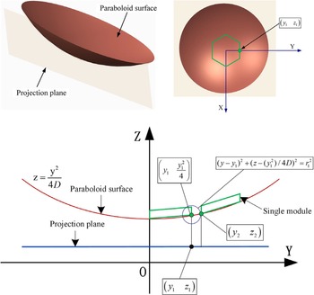
In order to obtain the conversation relationship between the assembly gap of the projection plane and the paraboloid surface, as shown in Fig. 3. The following calculation processes are proposed.
-
(1) The
$\left( {{y_1},{z_1}} \right)$
is a point projected on the projection plane of the central module. The point
$\left( {{y_1},{z_1}} \right)$
is located on the Y-axis of the coordinate system, and the
${y_1}$
equal to the
$\frac{{\sqrt 3 }}{2}d$
. -
(2) The point
$\left( {{y_1},\frac{{y_1^2}}{{4D}}} \right)$
can be obtained, which is located on the parabola surface. The point
$\left( {{y_1},\frac{{y_1^2}}{{4D}}} \right)$
is regarded as the centre, the design gap distance
${r_1}$
on the paraboloid is regarded as the radius. -
(3) A circle is drawn, its equation is
${\left( {y - {y_1}} \right)^2} + {\left( {z - \frac{{y_1^2}}{{4D}}} \right)^2} = r_1^2$
. Then,
${\left( {y - {y_1}} \right)^2} + {\left( {z - \frac{{y_1^2}}{{4D}}} \right)^2} = r_1^2$
and
${\rm{z}} = \frac{{{y^2}}}{{4D}}$
are solved simultaneously. The smaller solution is abandoned, and the point
$\left( {{y_2},{z_2}} \right)$
is obtained. Projecting the point
$\left( {{y_2},{z_2}} \right)$
to the plane, the starting point of the next module is obtained. -
(4) The assembly gap distance on the projection plane r is equal to
${y_2} - {y_1}$
.


Conversation relationship between the projection plane and the paraboloid surface.

After the above processes, the assembly gap distance of the paraboloid surface is converted to the assembly gap distance on the plane projection. Finally,
 $r$
is substituted to Equation (1), and the
 ${R_{Hex}}$
is calculated.
Repeating the above processes results in a series of position hexagons, whose position hexagons satisfy the gap distance
 ${r_1}$
on the paraboloid surface. Then, the centre point of each module is obtained by using the formula of definite proportion and separated points. At the same time, other points of each module on the projection plane can be obtained by utilising the vertex calculation formula of regular hexagon, and the nodes of all modules are projected onto the ideal parabola. Finally, the nodes of the module on the paraboloid surface are obtained.
3.0 Assembly error analysis
Since assembly errors seriously reduce the surface accuracy, this section proposes an analytical model of the assembly error based on the exponential product theory.
3.1 Decomposition of modular antennas
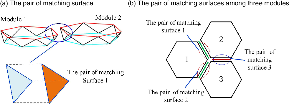
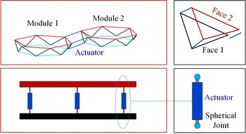
Because the assembly errors occur during the assembly process, the assembly positions of modules are actually inaccurate. In general, the assembly error of the module is equal to the error of two matching faces, as shown in Fig. 4(a).
Matching faces between two modules.

In the actual assembly process, the matching faces are used to determine the relative position of two modules. As shown in Fig. 4, the relative position between module 1 and module 2 is determined by the pair of matching faces 1. The relative position between module 1 and module 3 is determined by the pair of matching faces 2. Since the positions of module 2 and module 3 are determined, the pair of matching faces 3 does not affect the relative position between two modules. In summary, the matching faces can be divided into active matching faces and passive matching faces. The active matching faces determine the relative position between two modules, and the passive matching faces only represent the connection relationship.
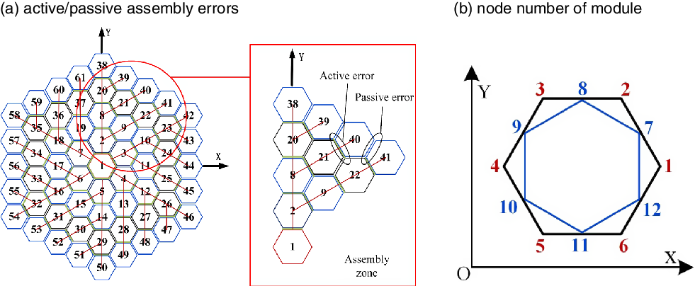
According to the type of matching faces, assembly errors can be divided into active errors and passive errors. Active errors and passive errors appear at the active matching face and passive matching face, respectively. During the assembly process, the distribution of the active assembly is determined by the assembly sequence. Meanwhile, the distribution of the active/passive errors also be determined. All modules are divided into the assembly zone based on the active errors, as shown in Fig. 5(a). There is an active error in the gap where the red line goes through, and the passive errors appear in the other gaps. The 12 nodes of a single module are numbered as shown in Fig. 5(b).
Assembly errors classification.

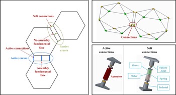
Because the positions of modules are inaccurate, their positions need to be adjusted. In order to get good adjustment effect, the active connections are installed at the active errors. The soft connection is installed in the passive error position to ensure the mobility of the antenna. The structure of soft connection is shown in Fig. 6.
Structure of the connection.

The active connection consists of a linear actuator, two pedestals and two sphere joints. The linear moto, inchworm actuator and ultrasonic moto also can be used as linear actuator [Reference Dong, Li, Wang and Ning24, Reference Li, Deng, Zhang, Hu and Liu25]. The soft connection consists of a sleeve, a slider, two springs and two pedestals. The slider is drove when the one of pedestal is compressed or stretched. Two springs are mounted on the upper and lower sides of the slider.
3.2 Exponential product expression of assembly error
Ideal node coordinates of the modular antenna can be obtained by applying the design method in Section 2. The geometric centre of the module is
 \begin{align}{P_{Mi}} = \frac{1}{4}\left( {P_i^1 + P_i^4} \right) + \frac{1}{4}\left( {P_i^7 + P_i^{10}} \right) + \left[ {\begin{array}{*{20}{c}}0\quad 0\quad { - h/2}\end{array}} \right]\end{align}
where
 $P_i^1$
,
 $P_i^4$
,
 $P_i^7$
and
 $P_i^{10}$
represent the node 1, 4, 7, 10 of the module
 $i$
,
 $h$
is the height of the module.
Because the geometry of mounting faces is triangle, the geometric centre of the triangle is calculated as
 \begin{align} P_{Ti}^k = \frac{1}{2}\left( {\left.P_i^n + P_i^{n + 1}\right) + \left[ {\begin{array}{*{20}{c}}0\quad 0\quad { - {\rm{h}}/2}\end{array}} \right]} \right)\end{align}
where
 $P_{Ti}^k$
is the geometric centre of the mounting face of the module i. Because the module includes six mounting faces, the value of
 $k$
ranges from 1 to 6. The n represents the node numbers of the module, which ranges from 1 to 12.
When modules i and
 $j$
are connected through the active mounting faces, the geometric centres of the mounting faces are
 $P_{Ti}^k$
and
 $P_{Tj}^k$
. Then, the centre point between the active mounting faces of modules
 $i{\rm{\;}}$
and
 $j$
is defined as
 \begin{align}V_{ij}^k = \frac{1}{2}\left( {P_{Ti}^k + P_{Tj}^k} \right)\end{align}
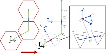
Each module is regarded as a rigid body, and the relationship between the module nodes and the geometric centre point is fixed. The assembly error transfer model is shown in Fig. 7. The
 $V_{ij}^k$
represents the virtual assembly point between the modules
 $i{\rm{\;}}$
and
 $j$
. Point
 ${P_{Mi}}$
is the origin of the global coordinate system.
Assembly error transfer model.

During the assembly mission, the assembly error is a variable with six degrees of freedom. Thus, exponential product theory is adopted to describe the assembly errors [Reference Chen, Wang and Lin26, Reference Fu, Fu and Shen27].
A virtual coordinate system is established at the virtual assembly point between two modules, and the directions of the virtual coordinate system are defined. The X-axis and Y-axis are equal to
 $\frac{{P_i^n - P_i^{n + 1}}}{{\left| {P_i^n - P_i^{n + 1}} \right|}}$
and
 $\frac{{P_{Ti}^k - P_{Tj}^k}}{{\left| {P_{Ti}^k - P_{Tj}^k} \right|}}$
, their expressions are
 ${\rm{\;}}{X_{ei}}$
and
 ${Y_{ei}}$
, respectively. The Z-axis is equal to
 $\frac{{{X_{e1}} \times {Y_{e1}}}}{{\left| {{X_{e1}} \times {Y_{e1}}} \right|}}$
.
When two modules are assembled, there will be displacement and rotation errors along the X-Y-Z axes. According to the screw theory, the principal part
 $\boldsymbol{{s}}$
of the screw is
 $\left( {\begin{array}{*{20}{c}}{{X_{e1}}}\quad {{Y_{e1}}}\quad {{Z_{e1}}}\end{array}} \right)$
. The physical meaning the rotation or displacement direction of the assembly error.
The subpart
 ${s_0}$
of the screw is
 \begin{align}{{\bf{s}}_{\boldsymbol{{0}}}} = \boldsymbol{{s}} \times \boldsymbol{{q}}\end{align}
where the
 $\boldsymbol{{q}}$
is the point coordinate position vector of the virtual assembly point
 $\left( {\begin{array}{*{20}{c}}{{x_{V_{ij}^k}}}\quad {{y_{V_{ij}^k}}}\quad {{z_{V_{ij}^k}}}\end{array}} \right)$
.
The screw axis of the assembly module in the global coordinate system is obtained.
The 4 × 4 matrix
 $\hat{\boldsymbol\xi} $
is defined as
 \begin{align}\hat{\boldsymbol\xi} = \left[ {\begin{array}{*{20}{c}}{\hat{\boldsymbol{{s}}}}\quad {{\boldsymbol{{s}}_{\boldsymbol{{0}}}}}\\[4pt] 0\quad 0\end{array}} \right]\end{align}
where the
 $\hat s$
is an antisymmetric matrix spanned by
 $\boldsymbol{{s}}$
.
Defining the rotation angle about the axis of virtual coordinates as d, the exponential product of rotation about this axis is
 \begin{align}{e^{\hat \xi \theta }} = \left[ {\begin{array}{c@{\quad}c}{{e^{\hat s\theta }}} & {\theta \boldsymbol{{I}} + \left( {1 - \cos \theta } \right)\hat{\boldsymbol{{s}}} + \left( {\theta - \sin \theta } \right){{\hat{\boldsymbol{{s}}}}^2}}\\[4pt]
0 & 1\end{array}} \right]\end{align}
Defining the displacement distance along the axis of virtual coordinates as d, the exponential product of the movement along the axis of translation is
 \begin{align}{e^{\hat \xi d}} = \left[ {\begin{array}{*{20}{c}}{{\boldsymbol{{I}}_{3X3}}}\quad {\boldsymbol{{s}}d}\\[4pt]
0\quad 1\end{array}} \right]\end{align}
When the assembly module rotates or moves along the virtual coordinate system, its position is
 \begin{align}{g_{ab}}\left( \theta \right) = {e^{\hat \xi \theta }}{g_{ab}}\left( 0 \right)\end{align}
where
 ${g_{ab}}\left( 0 \right)$
represents the ideal position of the assembly module,
 ${g_{ab}}\left( \theta \right)$
represents the position of the module with considering the assembly error.
The assembly error chain includes multiple modules, the geometric centre of the last module is
 \begin{align}{g_{ab}}\left( \theta \right) = {e^{{{\hat \xi }_1}{\theta _1}}}{e^{{{\hat \xi }_2}{\theta _2}}} \cdots {e^{{{\hat \xi }_n}{\theta _n}}}{g_{ab}}\left( 0 \right)\end{align}
The practical position of single module is obtained by Equation (11).
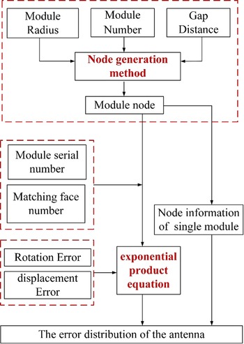
The above method can only be applied to analyse the rotation and displacement assembly error along the three directions of the virtual coordinate system. However, the actual assembly error is random variable in the actual on-orbit assembly mission. Thus, the concept of assembly error ball is proposed to describe the deformation surface.
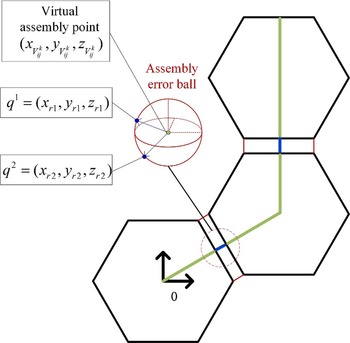
Figure 8 shows the proposed assembly error ball, which is centred on the virtual assembly point. A random point on the surface of the ball is selected as the actual assembly point of the module. Moreover, the direction vector between the random point and the virtual assembly point is regarded as the direction of the displacement error of the module. Another point is selected randomly, the direction vector between the point and the virtual point is regarded as the rotation axis of the rotation error. The rotation is selected within a specified range.
Error ball model.

The formulation of the error ball used here is as follows
 \begin{align}{\left( {x - {x_{V_{ij}^k}}} \right)^2} + {\left( {y - {y_{_{ij}^k}}} \right)^2} + {\left( {z - {z_{V_{ij}^k}}} \right)^2} = R_0^2\end{align}
where
 ${R_0}$
is the maximum displacement error in the assembly process, which can be adjusted based on actual assembly level. A point
 ${\boldsymbol{{q}}^{\textbf{1}}} = \left( {\begin{array}{*{20}{c}}{{x_{r1}}}\quad {{y_{r1}}}\quad {{z_{r1}}}\end{array}} \right)$
on the surface of the error ball is randomly selected. The direction vector is given by
 \begin{align}{\boldsymbol{{s}}^{\bf 1}} = \frac{{\left( {\begin{array}{*{20}{c}}{{x_{r1}} - {x_{V_{ij}^k}},}\quad {{y_{r1}} - {y_{V_{ij}^k}},}\quad {{z_{r1}} - {z_{V_{ij}^k}}}\end{array}} \right)}}{{\left| {\left( {\begin{array}{*{20}{c}}{{x_{r1}} - {x_{V_{ij}^k}},}\quad {{y_{r1}} - {y_{V_{ij}^k}},}\quad {{z_{r1}} - {z_{V_{ij}^k}}}\end{array}} \right)} \right|}}\end{align}
The screw is used to describe the rotation error. The principal part is
 ${\boldsymbol{{s}}^{\bf 1}}$
, and the subpart
 ${{\boldsymbol{{s}}^{\bf 1}}} \times {{\boldsymbol{{q}}^{\bf 1}}}$
.
The rotation angle θ is a random value. The exponential product of rotation is obtained by Equation (8).
Similar, the point
 ${{\boldsymbol{{q}}^{\bf 2}}} = \left( {\begin{array}{*{20}{c}}{{x_{r2}}}\quad {{y_{r2}}}\quad {{z_{r2}}}\end{array}} \right)$
is randomly selected. The direction vector is
 \begin{align}{{\boldsymbol{{s}}^{\bf 2}}} = \frac{{\left( {\begin{array}{*{20}{c}}{{x_{r2}} - {x_{V_{ij}^k}},}\quad {{y_{r2}} - {y_{V_{ij}^k}},}\quad {{z_{r2}} - {z_{V_{ij}^k}}}\end{array}} \right)}}{{\left| {\left( {\begin{array}{*{20}{c}}{{x_{r2}} - {x_{V_{ij}^k}},}\quad {{y_{r2}} - {y_{V_{ij}^k}},}\quad {{z_{r2}} - {z_{V_{ij}^k}}}\end{array}} \right)} \right|}}\end{align}
The principal part is
 ${{\boldsymbol{{s}}^{\bf 2}}}$
, and the subsidiary part
 ${{\boldsymbol{{s}}^{\bf 2}}} \times {{\boldsymbol{{q}}^{\bf 2}}}$
. Based on Equation (9), the exponential product formula of the displacement vector is obtained. Its displacement is equal to
 ${\rm{\lambda }}\left| {\left( {\begin{array}{*{20}{c}}{{x_{r2}} - {x_{V_{ij}^k}},} \quad {{y_{r2}} - {y_{V_{ij}^k}},}\quad {{z_{r2}} - {z_{V_{ij}^k}}}\end{array}} \right)} \right|$
, where λ is a random value between 0 and 1.
Finally, the ideal assembly model is applied to generate the exponential product of the rotation error and movement error by Equation (11) simultaneously.
 \begin{align}{g_{ab}}\left( {\theta ,d} \right) = {e^{{{\hat \xi }_1}{\theta _1}}}{e^{{{\hat \xi }_2}{d_2}}} \cdots {e^{{{\hat \xi }_n}{\theta _n}}}{g_{ab}}\left( 0 \right)\end{align}
When the assembly error appears on the modular antennas, the top and bottom surfaces generate the different deformations. Meanwhile, the thickness of module will affect the deformation. Because the performance of modular antenna is mainly affected by the deformation of the top surface. the deformation of the top surface is shown in this paper. The calculation process of the error model is shown in Fig. 9.
Flowchart of the modular antenna error analysis.

3.3 Shape adjustment of modular antenna
In order to ensure the node of each module places in the ideal paraboloid, active connections are installed between parts of the modules to adjust their positions as shown in Fig. 10.
Actuators installation of modular antenna.

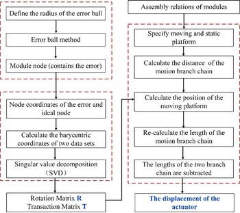
From Fig. 11, it can be seen that two mounting faces and three actuators can be regarded as a parallel mechanism. The mounting faces 1 and 2 are taken as the static platform and the moving platform of the parallel mechanism, respectively.
Definition of the assembly face.

The nodes that consider the assembly errors are regarded as deformation surfaces. In order to minimise the error between the deformed and ideal surface, the least square formula is applied as
 \begin{align}F\left( {R,T} \right) = {\rm{min}}\mathop \sum \limits_{i = 1}^N \|{Q_i} - {\left( {\boldsymbol{{R}}{P_i} + \boldsymbol{{T}}} \right)^2}\|\end{align}
where
 ${P_i}$
is the deformed data point set,
 ${Q_i}$
is the ideal data point set.
 $\boldsymbol{{R}}$
is the 3 × 3 rotation matrix,
 $\boldsymbol{{T}}$
is the 3 × 1 translation vector. The singular value decomposition is applied to solve Equation (16).
Barycentric coordinates of two data sets are
 \begin{align}\bar P = \frac{1}{N}\mathop \sum \limits_{i = 1}^N {P_i}{\rm{\;\;\;\;\;\;\;\;\;}}\bar Q = \frac{1}{N}\mathop \sum \limits_{i = 1}^N {Q_i}\end{align}
Through barycentric coordinates of two data sets, all remaining points are transformed as
 \begin{align}P_i^{kv} = P_i^k - \bar P{\rm{\;\;\;\;\;}}Q_i^{kv} = Q_i^k - \bar Q\end{align}
where the points
 $P_i^k$
and
 $Q_i^k$
belong to the corresponding two data sets.
A matrix is constructed
 \begin{align}\boldsymbol{{H}} = \mathop \sum \limits_{i = 1}^n P_i^{kv}\, {}^{\rm{*}}\,{\left( {Q_i^{kv}} \right)^T}\end{align}
Singular value decomposition (SVD) is performed on the matrix
 ${\rm{H}}$
.
 \begin{align}\boldsymbol{{H}} = \boldsymbol{{U}}\boldsymbol\Sigma {\boldsymbol{{V}}^{\bf T}}\end{align}
The rotation matrix R and translation matrix T are obtained.
 \begin{align}\boldsymbol{{R}} = \boldsymbol{{V}}{\boldsymbol{{U}}^{\boldsymbol{{T}}}},\, \boldsymbol{{T}} = \bar Q - \boldsymbol{{R}}^{\rm{*}}\bar P\end{align}
The matrix
 ${T_m}$
is formed with
 $T$
and
 ${\rm{R}}$
.
 \begin{align}{\boldsymbol{{T}}_{\boldsymbol{{m}}}} = \left[ {\begin{array}{*{20}{c}}\boldsymbol{{R}}\quad \boldsymbol{{T}}\\[4pt]
0\quad 1\end{array}} \right]\end{align}
Three new points
 $P_{ja}^N$
of the transformed moving platform can be obtained by multiplying the old three points
 $P_{ja}^O$
with
 ${T_m}$
. The length between two points of the new moving platform and the static platform is
 \begin{align}l_1^N = \left| {P_{ja}^N - P_{ja}^O} \right|\end{align}
The length change of the actuator is
 \begin{align}\Delta l = l_1^O - l_1^N\end{align}
The adjustment process is shown in Fig. 12.
Diagram of shape adjustment process.

4.0 Numerical simulation
4.1 Node generation
The parameters of the modular antenna are shown in Table 1. Projecting the assembly gap of the paraboloid onto the plane, the designed gap on the plane is obtained. The graph of ideal parabola and the gap distance projected to the plane are shown in Fig. 13(a) and (b), respectively.
Model parameter

Ideal paraboloid and gap distance on the plane.

According to the gap distance on the plane, each point’s coordinates of the hexagon are calculated, as shown in Fig. 14(a), and the details of the gap are shown Fig. 14(b). The Fig. 14(a) shows the projection of the modular antenna on the projection plane. Every module is the same size on the projection plane. Based on the theory in Section 2, it can be known that the gap distances in the projection plane are different. In order to obtain the equal gap distances between two modules in the paraboloid, the gap distances in the projection plane are projected to the paraboloid.
Plane projection of the modules and gap.

The partitioned hexagons are projected to the ideal paraboloid, as shown in Fig. 15(a). When the partitioned hexagons are projected to the ideal paraboloid, the shape of part hexagon will change. Because the module consists of two hexagons and some sway rods, their shape change can be achieved by adjusting the machine size. Based on the coordinates of the upper hexagon, the coordinates of the other components are obtained, as shown in Fig. 15(b).
Antenna structure.

4.2 Assembly error analysis and verification
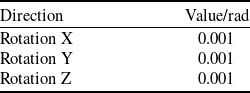
This paper takes the assembly errors between modules 1–6 and the module 0 as the objects to study the influence of rotation assembly error in three directions on the antenna, as shown in Table 2.
Direction and value of assembly errors

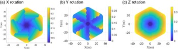
When the assembly error of six modules is 0.001rad along the X-axis, Y-axis and Z-axis, respectively, the deformation is shown in Fig. 16.
Surface deformation (the first module layers).

Figure 16 shows that the maximum deformation of the antenna is 0.035m, where an assembly error (0.001rad) appears in the first layer. And the assembly error of Y-axis has the least influence on the antenna reflector. From the Fig. 16, it can be obtained that the assembly errors will spread to outside modules, and the value of the error is tripled. In order to decrease assembly error of the antenna, the assembly accuracy of internal modules should be ensured.
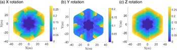
When the assembly error of the second module layers is 0.001rad along the X-axis, Y-axis and Z-axis, respectively, the deformation is shown in Fig. 17. From the Fig. 17, the assembly errors do not influence the inside modules. Compared with the results in Fig. 16, the maximum is smaller. We can know that the inner errors seriously affect the assembly error. Meanwhile, we can observe that the soft connection can effectively block error transmission.
Surface deformation (the second modules layers).

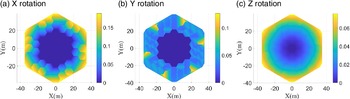
When the assembly error of the third module layers is 0.001rad along the X-axis, Y-axis and Z-axis, respectively, the deformation of modular antenna is shown in Fig. 18. The results show that the assembly errors of the X-axis and Y-axis are bigger than that of the Z-axis. However, the maximum deformation is still smaller than that of the Fig. 17.
Surface deformation (the third modules layers).

The maximum deformation of the surface caused by them is shown in Fig. 19 and Table 3. When the equal rotation errors appear at different assembly layers. It can be seen from the Table 3 that the first modules layers assembly error caused the maximum deformation. Therefore, the modules of the first modules layers should be assembled accurately in practical engineering application.
Deformation of the different module layers.

Maximum deformation of different module layers

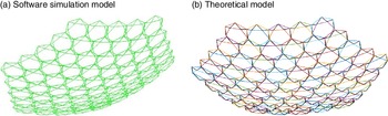
In order to verify the accuracy of the theorical model, the ideal antenna model is established in the dynamics simulation software, as shown in Fig. 20(a). The rotation pair is established at the ideal virtual installation point.
3D model of modular antenna.

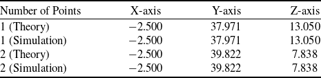
The rotation error with the same value is introduced into the software simulation model and the theoretical model, respectively. The random two points are measured. The 3D coordinates of the simulation and theoretical model are shown in Table 4. The results show that the theoretical model can describe antenna assembly errors accurately.
The 3D coordinate of the measured point

4.3 Analysis of adjustment algorithm
Firstly, the assembly position errors are 0.001m and the assembly rotation error is 0.001rad, respectively. According to the assembly error ball model, the deformed surface with the displacement and rotation assembly error is generated. Because the inner assembly error has the greatest influence on the deformation of the modular antenna, the actuators are installed on the inner module, as shown in Fig. 21(a).
The deformation of the modular antenna.

Based on the error ball concept, the original deformation is generated, as shown in Fig. 21(b). The RMS error of the modular antenna is 0.97mm. In order to decrease the RMS error, the adjustment method is applied to decrease this deformation. The adjusted deformation surface is shown in Fig. 21(c), its RMS error is 0.64mm. Comparing the Fig. 21(b) with Fig. 21(c), the area of larger deformation is significantly decreased.
5.0 Conclusions
In this paper, an analytical method for calculating assembly errors of modular antenna is proposed. Firstly, the module nodes generation method is proposed, which can design the modular antenna nodes on the paraboloid surface by considering the assembly gaps, where the assembly gaps between two modules are equal. Secondly, the assembly errors’ types are discussed, and the soft connection between two modules is designed. An analytical model is introduced to analyse the assembly error based on exponential product theory. In order to fully describe the assembly errors, the concept of the error ball is developed to construct the deformation surface, which has the advantages of being close to engineering practice. The node design method proposed in this paper is projected node from the projection plane to paraboloid. The modules with different geometric shapes are matched on the plane according to the specified assembly gaps, and the node coordinates on the paraboloid can be obtained. The assembly error analysis method can describe the assembly errors of the assembly module with 6 degrees of freedom, so that it can be applied to analyse the modules with different geometric shapes. Thirdly, a node position adjustment algorithm is presented in this paper because the position of the module affects the performance of modular antennas. Finally, the numerical results verify the correctness of the proposed method. The results show: (1) the deformation caused by the third module layers assembly errors is half of the first layer’s assembly errors, (2) the Y-direction assembly errors have the least influence on the surface accuracy, and (3) the adjustment algorithm decreases the RMS from 0.97 to 0.64mm.
Acknowledgment
This work is supported the National Natural Science Foundation of China (Grant No. 51775403).