


I. INTRODUCTION
Magnetic materials have found extensive use in microwave systems (filters, isolators, phase shifters, etc.). Depending on the microwave application, the magnetization state of the ferrite varies. To describe this dynamic behavior, a tensorial quantity has to be defined. Assuming a static magnetic field H dc in the Oy direction, the dispersion and the anisotropy exhibited by ferrites at any magnetization state are fully described at a frequency f by the permeability tensor (1):

Nowadays, high frequency measurements of ferrites are made mainly in two magnetization states: the demagnetized and saturated states [1]. For the characterization of the microwave behavior of ferrites at partially magnetized states, we have previously developed two different techniques at our laboratory. The first is based on the analysis of a rectangular waveguide partially filled with the magnetic material [Reference Quéffélec, Le Floc‘h and Gelin2]. This technique is however limited to the mono-mode frequency band of the waveguide (8–12 GHz for a X band guide). The second technique is based on the used of a microstrip transmission line [Reference Quéffélec, Mallégol and Le Floc’h3]. This technique is based on transmission line theory and thus it is valid from 0 up to a few GHz. Our first challenge in this paper is to develop an EM characterization method to measure a tensor quantity (permeability tensor) in a broad frequency range (0.1–10 GHz). Furthermore, our aim is also to propose new approaches to avoid problems currently met with broadband measurement techniques for dielectric and magnetic materials. Thus, the advantages of the measurement method we propose, compared to conventional broadband methods, are:
– The use of a specific wideband inverse problem procedure, to avoid the uncertainty problems that appear at certain frequencies due to dimensional resonances. This enables us to exploit a broad range of frequencies (0.1 – 10 GHz) without decreasing sample lengths, which permits to increase the sensitivity of the cell.
– The use of a non-50 Ω measurement cell to improve the differential measurement procedure (measurement performed with the empty cell are subtracted from measurements performed with samples under test) and then the accuracy of the method.
II. DESCRIPTION OF THE METHOD
A) Principle of the method
The characterization method that we present is divided into two main parts. The first part is the direct problem in which the theoretical S-parameters of the measurement cell are determined. The second part is the inverse problem in which the components of the permeability tensor μ, κ, and the permittivity ɛ of the material are going to be measured.
To fully describe the dynamic response of magnetic materials, including losses, complex quantities have to be taken for the permeability tensor components: μ = μ′ − jμ″, κ = κ′ − jκ″ and for the permittivity ɛ = ɛ′ − jɛ″. In order to solve a square system of equations, three independent complex scattering parameters have to be measured. This forces a non-reciprocal behavior of the measurement cell (S 21≠S 12). For this, the cross section of the measurement cell must be asymmetrically loaded (in terms of EM properties).
B) Measurement cell: asymmetrically loaded stripline
The characterization method proposed is based on the use of an asymmetrically loaded stripline (Fig. 1a). A section of this line is filled at the sides with two dielectric slabs showing different permitivities (ɛ 1 and ɛ 2) and at the center with two identical samples of the magnetic sample under test. For the sake of notation, we are going to call the loaded section the volume of the line that contains the materials and the air sections the rest of the line (Fig. 1b). The presence of the magnetized magnetic material in the line concentrates the energy to one side of it, depending on the propagation direction (field displacement effect [Reference Straus4]). Figure 2a shows the energy repartition for the forward direction. For the backward direction all fields are displaced to the opposite side of the strip conductor (Fig. 2b). This effect, combined with the fact that for each direction the wave interacts mostly with a different dielectric slab, gives rise to the non-reciprocal behavior of the structure (S 21 ≠ S 12).
Asymmetrically loaded strip-transmission line: (a) Strip-transmission line, and (b) Sections of the line.

Equivalent model of the transmission line: (a) EM pattern in the forward direction, (b) EM pattern in the backward direction, and (c) Theoretical equivalent structure.

We have chosen a strip transmission line over the other types of microwave lines (coplanar, microstrip, etc.) mainly for two reasons. The first one is that in the empty cell, the dominant mode is purely the transverse electro magnetic (TEM) while in the other types of line the dominant mode is quasi-TEM. The main advantage of the TEM mode is that it is fully described by the classical definitions of EM fields and therefore has a straight-forward insertion in a full-wave analysis. The second one is that this topology allows “in-situ” measurements. Conventional microwave applications of magnetized ferrites are circulators/isolators. These devices are generally realized using the stripline technology (for example, Y-junction circulators). As the permeability of magnetic materials depends on their shape due the demagnetizing fields, this “in-situ” criterion becomes very important while measuring. To avoid the fringing field effects, the width of the strip a is greater than the height b between the strip and the ground planes [Reference Hines5]. Consequently, it is assumed that the energy inside the line is confined between the strip and the ground planes. Thus, from an EM point of view, the loaded section can be represented by the theoretical equivalent structure shown in Fig. 2c. In this structure, perfect electric conductors (PEC) are added to replace the strip and the ground conductors and perfect magnetic conductors (PMC) are added, in accordance with the EM field pattern, to close the energy inside. In this equivalentstructure only one half of the measurement cell is described. In the other half all the EM fields are mirror quantities with inverted phases (Fig. 2a), and therefore they do not modify the energy repartition inside the cell. After an optimization phase of the measurement cell, its physical dimensions are established as: a = 9 mm and b = 1 mm. With this dimensions the characteristic impedance of the empty cell becomes 18.4 Ω, which is the base for the differential measurements procedure used in the inverse problem.
C) Direct problem: calculated S-parameters
The direct problem can be described in two parts. The first part is the full-wave analysis of the loaded section. From this analysis, the dispersion diagram for the first N modes of the loaded section of the line is found. In the second part, a mode–matching technique is used in the two discontinuities in the z–direction (air/load and load/air in Fig. 1b). This technique leads us to the theoretical S-parameters of the measurement cell. The value of N is chosen in order to ensure the convergence of the S-parameters of the cell.
1) Dispersion diagram
As the incident TEM mode in the air sections does not find discontinuities in the Oy direction of the cross section (Fig. 2c), only a hybrid quasi-TEM and the transverse electric (TEn0) modes are excited in the loaded section [Reference Hines5]. This means that the propagation inside the loaded section becomes independent of y, forcing the E x, E z, and H y components to be null. In this condition, the full-wave analysis of the line begins with the definition of the existing EM fields (H x, H z, and E y) inside each material, taking into account the boundary conditions defined in the equivalent model (PEC and PMC). Then, applying the continuity equations at both dielectric/ferrite discontinuities in the Ox direction, the system ofequations (2) is found:
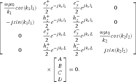
In this system k 1,2, l 1,2 are the wave numbers and widths of the dielectrics 1 and 2, k x is the wave number inside the ferrite, e i± (in V/m) and h i± (in A/m) are the expressions for the EM fields magnitudes inside the ferrite ((+) for forward and (–) for backward), L = l 1 + e p where e p is the width of the ferrite sample, ω is the angular frequency, A,B,C,D are integration constants, and μ 0 is the permeability in vacuum. The dispersion equation (3) is obtained annulling the determinant of the matrix in (2):

This equation depends on frequency (ω), the EM properties of the materials (μ, κ, ɛ), and the propagation coefficient γ = β − jα, where β is the phase constant and α is the attenuation constant. The values of γ for which the dispersion equation (3) is satisfied, correspond to the propagation constants of the modes inside the loaded section. Figure 3 shows the solutions of γ found for a magnetized case. This diagram shows the first 10 propagated modes (five forward and five backward) in the loaded section of the line.
Dispersion diagram with the dielectrics ɛ 1 = 1.07 − j0.001 (l 1 = 2 mm), ɛ 2 = 36.5 − j0.01 (l 2 = 2 mm) and a YIG ferrite with ɛ f = 13.5 − j0.01, H a =11936 A/m, 4π Ms =0.182 T, ΔH = 1671 A/m and H dc = 39788 A/m (e p = 5 mm). N = 10 modes.

The non-reciprocity of the cell is evidenced by the differences of phase constants found between the same mode for both directions of propagation (i.e., TE10 mode). This diagram also shows the apparition of quasi-TEM modes. These are the dominant modes in the loaded section and should carry most part of the EM energy. But as an effect of the gyromagnetic resonance of the magnetized ferrite, we see that at low frequencies the higher–order modes become propagated in the form of magnetostatic modes. In this condition, a mode that showed an evanescent behavior for a classical line becomes a propagated mode in this non-reciprocal line. Thus, at certain frequencies, the superior modes can present values of propagation constant greater than those of the dominant mode. Therefore, to perform a good description of the EM propagation inside this type of ferrite-loaded structures, it is critical to take into account the contributions of the first significant modes (dominant + superiors). This result shows the importance of performing a full-wave analysis on the modeling of non-reciprocal devices.
2) S-parameters
Once the propagation constants of the modes in the loaded section γ + and γ − (direct problem) and the air sections γ 0 (EM classical theory) of the lines are known, the S-parameters of the measurement cell can be calculated. This is done performing a mode–matching technique in the Oz direction (Fig. 4). In this direction, the incident TEM mode interacts with the air/materials discontinuities (P 1 and P 2) reorganizing the energy in the form of reflected and transmitted TEM modes in the air sections, in form of excitation of dominant quasi-TEM and superior TE n0 modes inside the loaded section, and in form of evanescent modes in the neighborhood of the discontinuities.
Mode–matching technique.

This propagation phenomenon is described by the continuity equations in the plane P 1 by


and in the plane P 2 by


In these equations d 0 is the length of the loaded section. The index n corresponds to the modes in the air section, while the indexes i and r correspond to the forward and backward modes in the loaded section. The variables r n, t n, T i, and R r correspond to the coupling coefficients that describe the repartition of the energy between the different sections of the line. The resolution of this system of equations is based on the orthogonality property of modes [Reference Collin6]. Using this property, the coupling coefficients for the N modes are deduced. Then, the reflection parameter S 11 and the transmission parameter S 21 are related to the coupling coefficients of the dominant mode in the air section r 1 and t 1 by


where H 1 represents the magnetic field of the dominant mode in the air sections and
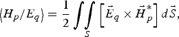
where (*) denotes the complex conjugate. To obtain the reflection parameter S 22 and the transmission parameter S 12, the same process is used considering the incident TEM mode entering from the opposite side (P 2).
D) Validation of the full-wave analysis: measurement of material properties
In order to measure the materials properties  and ɛ, a broadband optimization procedure is performed. In this optimization procedure the theoretical S-parameters are going to be matched with the measured S-parameters minimizing the error function:
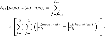
In this function the optimization variables are the material properties functions μ(ω), κ(ω), and ɛ(ω). To represent the resonance nature of the permeability components, Lorentzian functions are used for μ(ω) and κ(ω) [Reference Gelin and Quéffélec7]. To represent the dispersion nature of the permittivity, a Debye function is used for ɛ(ω). The broadband optimization procedure is done using the Matlab sub routine lsqnonlin that is based on the interior-reflective Newton method. In this procedure, we compare both S-parameters curves over the entire frequency range at the same time. By doing this, we are able to use only the magnitude of the S-parameters in the error function (11). This is done to avoid the uncertainties found in the phases of the S-parameters which are related to the low S/N ratio in the measured signals at the dimensional resonances. Once the curves are matched, the optimized functions for μ(ω), κ(ω), and ɛ(ω) will represent the measured material properties of the sample.
To validate our direct problem, we have performed our characterization method in limit cases. The first case that we present is the measurement of a well–known dielectric: the epoxy resin SEP. In Fig. 5a, we show in a dotted line the measured S-parameters using the SEP dielectric as sample under test and in solid line the optimized S-parameters obtained from our direct problem. In Fig. 5b, we show the Debye function obtained from this optimization procedure (μ = 1 and κ = 0). In this figure we also show the measurement of the SEP dielectric done with resonant methods (at 2 and 10 GHz) by different French laboratories (SNPE, CEA, and LGEP). We see from this result that our direct problem describes the propagation phenomenon inside the measurement cell (Fig. 5a) and that the optimized property function ɛ(ω) is in total accordance with the measurements performed with other standard techniques.
Validation of the measurement method using the SEP epoxy dielectric as sample under test. ɛ 1 = ɛ 2 = ɛ f = SEP, l 1 = l 2 = 2 mm, d 0 = 7 mm and e p = 5 mm with N = 10. (a) Measured and optimized S-parameters. (b) Measurement of ɛ(w).

The second limit case that we present is using a YIG ferrite in a demagnetized state. Figure 6(a) shows the measured and optimized S-parameters and Figure 6(b) shows the measured functions for the ferrite properties ɛ, μ, and κ.
Validation of the measurement method using the ferrite YIG101 from Temex Ceramics. ɛ 1 = ɛ 2 = 1 − j0.001, l 1 = l 2 = 2 mm, d 0 = 18 mm and e p = 7 mm with N = 14. (a) Measured and optimized S-parameters. (b) Measurement of ferrite properties.

As we can see in Fig. 6a, our direct problem also describes the propagation phenomenon inside a ferrite–loaded line. The resonances found in the S 11 curve are the consequence of using a long ferrite sample (d 0 = 18 mm). This resonances do not interfere in our method due to the wideband inverse problem that we use. On the contrary, in our measurement method we are encouraged to use long samples to improve its sensitivity. The measured permittivity ɛ of the ferrite is inaccordance with the provider's supplied characteristics. As expected, we obtain in this case values for κ that are almost null (H dc = 0). From the μ curve, we see that the gyromagnetic resonance frequency of this ferrite sample is allocated at 938 MHz. This high value of frequency is due to the ferrite's shape (parallelepiped slab), which enforces demagnetizing fields. In toroidal YIG ferrite samples, in which demagnetizing fields do not exist, these resonances are measured at around 1 to 300 MHz. This shows the importance of “in-situ” measurement techniques, like ours, which take into account as much EM phenomena as possible.
III. CONCLUSIONS
A full-wave analysis and a broadband optimization procedure have been developed for a asymmetrically ferrite-loaded transmission line. This is the first stage in the development of a new characterization method that allows the measurement of the permeability spectra of ferrites taking into account their magnetization state. This method intends to expand the validation range and accuracy of the previous methods developed in our laboratory. The next stage in the development of this measurement technique isto acquire non-reciprocal measurements from the ferrite-loaded line at different magnetization states and to improve the optimization procedure in order to be able to measure the EM properties of the ferrite μ(ω), κ(ω), and ɛ(ω) at any magnetization state.
 Jorge Lezaca received an electronics engineer diploma in 2007 from the National University of Colombia and he is actually coursing his Ph.D studies at the University of Brest, France. His main research interests are the characterization and modeling of propagation of electromagnetic waves and the microwave circuit design.
 Patrick Quéffélec received his Ph.D. in 1994 in electronics from the University of Brest, France. At Present, he is a professor at the University of Brest at the Lab-STICC laboratory. His research activities deal with electromagnetic wave propagation in magnetic materials and the analysis of measurement methods for the microwave characterization of materials.
 Alexis Chevalier received his Ph.D. in 1999 in electronics from the University of Brest, France. At Present, he is an assistant professor at the University of Brest at the Lab-STICC laboratory. His research interest focuses on modeling and characterization of materials for microwave applications.



