I. INTRODUCTION
The successful transition of advanced nuclear energy concepts into commercial plants requires improvements in four key areas Reference Kessler1 : improvement of the economic competitiveness, meeting increasingly stringent safety requirements, adhering to the criteria of sustainable development, and public acceptance.
One method for achieving the sustainability goals of maximizing the use of available energy content in the nuclear fuel and of minimizing the amount of long-lived radioactive waste that must be disposed is to adopt a fast reactor-based fuel cycle that includes transmutation of actinides. Reference Stanculescu2–Reference Bianchi, Calabrese, Glinatsis, Lantieri, Monti and Vettraino4 A description of how the proposed advanced reactor concepts of the Generation IV initiative address plutonium and higher actinide creation and use can be found in Refs. Reference Lennox, Millington and Sunderland5 and Reference Marques6. A major difference using a fast reactor spectrum reactor is that the core and fuel assembly materials are all exposed to a much larger total radiation dose. These materials must maintain adequate properties despite this increased radiation damage. The damage to cladding can be even larger in heterogeneous fuel assemblies with special fuel elements specifically designed to burn actinides that are exposed to a very large radiation dose. Reference Salvatores7 Similar concerns about high-dose radiation stability are also raised in the context of the development of fusion energy systems, which create higher energy neutrons that cause greater damage per neutron. Reference Bloom, Busby, Duty, Maziasz, McGreevy, Nelson, Pint, Tortorelli and Zinkle8,Reference Baluc, Abe, Boutard, Chernov, Diegele, Jitsukawa, Kimura, Klueh, Kohyama, Kurtz, Lasser, Matsui, Moslang, Muroga, Odette, Tran, van der Schaaf, Wu and Zinkle9
The majority of fast reactor development worldwide has focused on sodium-cooled fast reactors with smaller efforts on lead-cooled, gas-cooled, and molten-salt cooled fast reactor systems. In the United States, the original material of choice for fast reactor structural components was 316 austenitic stainless steel. When an unacceptable volumetric expansion due to void swelling was discovered to be life-limiting in 316 stainless steel, focus for cladding and duct application shifted to ferritic and martensitic steels. Reference Gelles10 The majority of the research on ferritic–martensitic steels focused on 9–12Cr steels. The higher Cr concentration alloys show increased resistance to corrosion and void swelling but the 9Cr material is more resistant to irradiation embrittlement at 350 °C. Reference Gelles10 HT9 (12Cr–1Mo, see Table I) was chosen for cladding and duct application for both the EBR-II and FFTF reactors in the U.S. fast reactor programs.
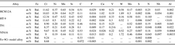
Alloy composition.

To develop improved structural materials for fast reactor systems requires a detailed understanding of the critical in-service degradation mechanisms. A number of recent reviews have outlined the materials' challenges in the operation of a fast reactor. Reference Allen, Busby, Meyer and Petti11–Reference Allen, Burlet, Nanstad, Samaras and Ukai16 The challenges can broadly be grouped into those associated with corrosion, typically in either sodium or lead alloys, and those associated with radiation damage, as well as high-temperature thermal creep strength and creep-fatigue behavior.
In 2001, Klueh and Harries provided a detailed description of the known effects of irradiation on ferritic and martensitic steels. Reference Klueh and Harries17 These alloys must have adequate response to a number of property changes including: interfacial segregation and precipitation, mechanical property changes including tensile, creep, and impact properties, and dimensional changes due to void swelling. Each of these property changes is driven by associated microstructural changes. The following sections briefly highlight the key features of the above property changes as described by Klueh and Harries. Reference Klueh and Harries17
A. Interfacial segregation and precipitation
Changes in precipitate density and size can affect mechanical and corrosion resistance properties. Under radiation, nonequilibrium precipitates can form due to the creation of point defects far in excess of equilibrium values that drive subsequent radiation-induced segregation (RIS) of elements, leading to the formation of unique precipitate phases. Additionally, the formation of equilibrium phases can occur more rapidly due to irradiation-enhanced diffusion. The phases formed in ferritic–martensitic steels under irradiation include Cr-rich ferrite, M6X (η), Chi (χ), G, Laves, Sigma (σ), M3P, and MP.
RIS is a local change in composition associated with the flux of radiation-produced vacancies and interstitials to sinks such as grain boundaries. At the time the review by Klueh was written, the reported segregation trends, based on limited data, were that under irradiation Cr depleted at interfaces, as did Ni, Si, and P, and Mo and Mn could either deplete or enrich. As will be reported in detail in this work, the trends in segregation are more complex than this early picture.
Pre-existing precipitate phases, typically introduced into the steel purposely, can either dissolve due to the displacement of atoms caused by collisions with high-energy particles or coarsen due to high temperatures. Of key research concern is the response to radiation of nanometer-scale oxide clusters introduced into ferritic–martensitic steels to improve the high-temperature creep resistance. Reference Odette, Alinger and Wirth18 Steels with these nanoclusters have been termed oxide dispersion-strengthened (ODS) steels and nanostructured ferritic alloys (NFAs).
B. Mechanical properties
Creep in ferritic–martensitic alloys under radiation is typically described by a semiempirical relationship with the creep strain proportional to stress and total radiation fluence with temperature effects described by a creep coefficient with a temperature dependence that follows an Arrhenius expression. The reported creep dependence does not change significantly across different types of high-chromium ferritic–martensitic steels.
Changes in tensile properties due to radiation are temperature dependent. At temperatures below roughly 400–450 °C, changes in the microstructure under radiation lead to hardening, with an increase in yield and ultimate tensile strength and a decrease in uniform and total elongation. Above 400–450 °C, the radiation hardening is not present. The temperature at which this transition happens is alloy dependent.
A concern in using ferritic–martensitic steels at lower temperature is a loss of toughness. The majority of the data on changes in impact resistance come from Charpy impact specimens that measure the change in ductile-to-brittle transition temperature (DBTT) as a function of irradiation dose. Key findings reported by Klueh are that the DBTT shifts are larger at lower temperature, the alloy composition does affect DBTT shifts with 9Cr alloys having a smaller shift than 12Cr alloys, and the DBTT is dependent on alloy and processing history.
C. Swelling
Under radiation, materials can isotropically increase in volume (a process known as swelling) due to the accumulation of radiation-produced vacancies into voids and the accompanying accumulation of interstitials into dislocation loops. Reference Garner and Konings19 Void swelling progresses from a nucleation phase, where voids begin to form, to a transient phase where void swelling increases are small, to a steady state phase in which swelling proceeds at a fairly constant rate (percent swelling per dpa). Dimensional increases due to swelling in ferritic and martensitic steels are much lower than in austenitic steels at the same irradiation dose. Irradiations out to 200 displacements per atom in fast reactors indicated that the steady-state swelling in the ferritic-martensitic (FM) steels is roughly 0.2%/dpa and the 9Cr steels swelled more than the 12Cr steels (completing the transient phase of the swelling more rapidly). Because proposed advanced reactor concepts envision extending component life beyond the 200 dpa reached in any previous testing, understanding the factors that control the transition between transient and steady-state swelling is critical in predicting the performance.
As noted in a recent review by Zinkle and Ghoniem, Reference Zinkle and Ghoniem20 designing materials for performance in high-radiation fields can be accelerated through a carefully chosen combination of advanced multiscale modeling paired with appropriate experimental validation. The studies reported in this work, the combined efforts of six universities working together as the Consortium on Cladding and Structural Materials (CCSM), use that approach to focus on improving the scientific basis for the response of ferritic–martensitic steels to irradiation. A combination of modern modeling techniques with controlled experimentation has specifically focused on improving the understanding of RIS, precipitate formation and growth under radiation, the stability of oxide nanoclusters, and the development of dislocation networks under radiation. Experimental studies use both model and commercial alloys, irradiated with both ion beams and neutrons. The compositions of the four alloys used in these studies are listed in Table I. Transmission electron microscopy (TEM) and atom probe are combined with both first-principles and rate theory approaches to advance the understanding of ferritic–martensitic steels beyond that described in the 2001 compilation by Klueh.
II. RADIATION-INDUCED SEGREGATION
This collaboration resulted in a robust understanding of RIS behavior in FM alloys. Previously, this phenomenon was poorly understood in FM alloys, as only a few studies had been conducted, and they resulted in inconsistent and inconclusive RIS measurements, specifically of the direction of Cr RIS. This collaboration enabled a systematic and thorough study of RIS over a wide range of experimental conditions. Multiple FM alloys, both commercial and model, were investigated. Irradiations were carried out at multiple facilities using protons, ions, and neutrons. RIS was studied as a function of irradiation dose, temperature, and grain boundary character. Collectively, the results of this collaboration have enabled us to demonstrate that the direction of Cr RIS is a function of irradiation temperature and bulk Cr content. Additionally, this enables us to make sense of the previously inconclusive data on Cr RIS in FM alloys throughout the literature.
A. Background on RIS
RIS is a nonequilibrium phenomenon observed in irradiated metallic alloys, whereby the alloy composition is altered near certain microstructural features, notably grain boundaries. Reference Was21 This process is driven by the diffusion of radiation-produced point defects to these microstructural features, which act as defect sinks. This flux of defects to the sink results in the enrichment of some alloy components and the depletion of others, based upon their relative diffusivities: components which diffuse more quickly via vacancies will tend to deplete near the sink, while components that diffuse more quickly via interstitials will tend to enrich near the sink. Most models for understanding and predicting RIS are based upon the inverse Kirkendall (IK) theory as described by Wiedersich et al. Reference Wiedersich, Okamoto and Lam22 In this approach, a set of coupled diffusion equations are solved in one dimension to describe the flux of defects and alloy species to the sink. The principal material parameter in the IK model of RIS are the insterstitial and vacancy diffusivities of each alloying component, as well as the nature of the sink. Many aspects of RIS in steels were recently reviewed in Refs. Reference Was, Wharry, Frisbie, Wirth, Morgan, Tucker and Allen23 and Reference Ardell24.
RIS is well understood in austenitic Fe–Ni–Cr alloys, in which Cr consistently depletes at grain boundaries under irradiation. Since Cr is included in these alloys in part to provide corrosion resistance, a reduction of Cr near grain boundaries is problematic, as it may increase susceptibility to irradiation-assisted stress corrosion cracking. Reference Was21,Reference Hanninen and Aho-Mantila25–Reference Was and Bruemmer27 The modified inverse Kirkendall (MIK) model Reference Allen and Was28 accurately predicts the direction and magnitude of RIS in austenitic Fe–Ni–Cr alloys. According to the MIK model, Cr depletes near grain boundaries due to fast Cr diffusion via vacancies; while interstitials are also present, the MIK model assumes that there is no species bias in the interstitial flux. Other models indicate that interstitial diffusion may either enhance Reference Nastar, Bellon, Martin and Ruste29 or suppress Reference Barnard, Tucker, Choudhury, Allen and Morgan30,Reference Tucker, Najafabadi, Allen and Morgan31 Cr depletion. But all models concur that Cr depletion in Fe–Ni–Cr alloys is ultimately the result of vacancy-dominated diffusion.
RIS may also present concerns for FM alloys proposed for use as candidate materials for structural components in fusion and some advanced fission reactor designs. These alloys contain a significant bulk Cr concentration, often 8–12 wt%, so Cr enrichment due to RIS could lead to precipitation of the brittle Cr-rich α′ phase. But prior to the CCSM collaboration, RIS behaviors in FM alloys were not well understood. In a summary of fifteen published studies of Cr RIS in FM alloys, there are eight cases of Cr enrichment and seven cases of Cr depletion. The inconsistency of these results, alloys studied, analysis techniques, and irradiation conditions, presented an inconclusive landscape of Cr RIS in FM alloys. Further, the IK model had not been applied to FM alloys, so there was no mechanistic basis for the experimental results.
The CCSM collaboration afforded the opportunity to perform a systematic benchmarking of RIS behavior in FM alloys, using a consistent group of model and commercial alloys, irradiated using consistent techniques, and analyzed using consistent methods. The partnership between experimental and computational researchers in the CCSM collaboration created a bridge between RIS measurements and first principles-based models; through this connection, CCSM has been able to use the IK model to explain RIS in FM alloys.
This section will present the three major accomplishments of the CCSM collaboration with regard to RIS. First, the collaboration clarified the direction of Cr RIS in FM alloys using consistent and systematic experimental measurements as a function of irradiation temperature, grain boundary structure, and irradiation dose rate. Second, the collaboration used computational models to augment experimental observations and develop a mechanistic understanding of RIS in FM alloys. Finally, this collaboration gained an understanding of the role of RIS in the context of other microstructural processes in irradiated FM alloys.
B. Consistent and systematic experimental measurements of RIS in FM alloys
The inconclusivity of early RIS measurements in FM alloys was due in large part to the fact that every study used a different alloy, temperature, dose, and irradiating particle. This precluded the identification of any meaningful trends or patterns in the data. The CCSM collaboration aimed to conduct a systematic set of experiments, changing only one experimental parameter at a time, to isolate the effects of temperature, dose, irradiating particle, and alloy composition, on RIS behavior. The effect of grain boundary structure on RIS was also investigated. The dependence of RIS on each of these factors is discussed in the following subsections.
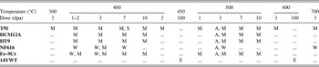
Experiments focused on FM steels containing 9–12 wt% Cr, irradiated over temperature range of 300–700 °C, as is relevant to proposed next-generation fast reactor designs. Irradiations were carried out to doses between 1 and 10 dpa. Irradiations were conducted across multiple institutions including the University of Wisconsin Ion Beam Laboratory (UWIBL), the Michigan Ion Beam Laboratory (MIBL), and the Idaho National Laboratory Advanced Test Reactor (ATR). Samples used at all participating institutions originated from the same heats of alloys to limit heat-to-heat variability in irradiation response. Table I summarizes the experimental conditions investigated.
Post-irradiation characterization of RIS was also carried out consistently between all involved institutions. Grain boundary RIS measurements were conducted using scanning transmission electron microscopy and energy dispersive x-ray spectroscopy (STEM-EDX) using either one-dimensional line profiles or spectrum images at a point-to-point resolution of ∼1.5 nm. Quantification was completed using the Cliff–Lorimer scheme. Reference Williams and Carter32 For a more detailed discussion about the microscopy techniques and quantification, please refer to Refs. Reference Field, Barnard, Parish, Busby, Morgan and Allen33–Reference Wharry and Was35.
1. Temperature dependence of RIS
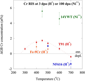
The behavior of Cr RIS as a function of temperature has been measured experimentally in four alloys: an Fe–9Cr model alloy, commercial T91 and NF616 FM alloys, and 14YWT ODS alloy. The T91, NF616, and Fe–9Cr model alloys were irradiated with 2.0 MeV protons to 3 dpa between 300 and 600 °C, at MIBL (T91 and Fe–9Cr) and UWIBL (NF616). The 14YWT was irradiated to 100 dpa between 450 and 600 °C with 5.0 MeV Ni++ ions at the Environmental Molecular Sciences Laboratory (EMSL) at Pacific Northwest National Laboratory (PNNL).
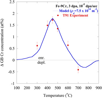
In all of the 3 dpa proton-irradiated specimens, only small amounts of Cr RIS, never exceeding ∼2 at.%, were observed. The 14YWT exhibited a larger amount of Cr RIS, on the order of ∼5 at.%, due to the higher irradiation dose level studied (100 dpa). All the four alloys exhibit a maximum amount of Cr RIS at temperatures near 400–450 °C, with smaller magnitudes of Cr RIS at temperatures <400 °C and >450 °C. The result is a bell-shaped temperature dependence between 300 and 600 °C (Fig. 1). The bell-shaped temperature behavior is attributed to point defect mobility. At low temperatures, defects are immobile and cannot diffuse to sinks, severely limiting the amount of segregation. At elevated temperatures, high point defect mobility induces back-diffusion, removing concentration gradients. Hence, the most segregation occurs at moderate temperatures.
Bell-shaped temperature dependence of Cr RIS in several FM alloys, all irradiated to 3 dpa, showing crossover from Cr enrichment to depletion.

Between 600 and 700 °C, Cr RIS reverts from enrichment to depletion, a behavior that will henceforth be referred to as the “crossover”. Correspondingly, Fe depletion also reverts to Fe enrichment. The crossover is observed in both T91 and NF616. This is one of the most notable and unique behaviors of RIS in FM alloys, and such behavior has not previously been reported in any other alloy system.
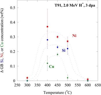
Minor alloying elements (Si, Ni, Cu) also enrich according to a bell-shaped temperature dependence (Fig. 2). However, they segregate only between 400 and 500 °C. Since some Cr and Fe RIS persists <400 °C and >500 °C, the mechanism of RIS of the minor elements differs than that of Cr and Fe.
Temperature dependence of Si, Ni, and Cu RIS in alloy T91 irradiated with 2.0 MeV protons to 3 dpa, showing enrichment between 400 and 500 °C and RIS suppression at 300 and 600 °C.

2. Grain boundary structure dependence of RIS
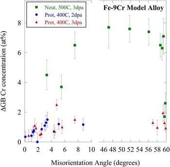
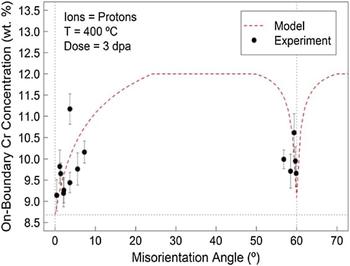
RIS at grain boundaries is directly related to the flux of point defects to grain boundary, the capture of the point defect flux by the boundary, and ultimately their destruction. RIS can be used to imply the grain boundary point defect sink efficiency and mechanisms related to the efficiency. To better understand the role of grain boundary structure on the RIS dependence in FM steels, a systematic study was conducted on a Fe–9Cr model steel irradiated with 2.0 MeV protons to 2–3 dpa at 400 °C, and with fast neutrons to 3 dpa at 500 °C. Binning spectrum images along the length of the grain boundary and computing an average composition for the grain boundary determined the grain boundary composition; refer to Ref. Reference Field, Barnard, Parish, Busby, Morgan and Allen33 for more details. Here, the grain boundary misorientation angle is used as a descriptor for the grain boundary structure. There is a clear dependence of Cr RIS on grain boundary structure (Fig. 3), based on measurements across multiple grain boundaries in Fe–9Cr irradiated between 2 and 3 dpa at 400–500 °C with either protons or neutrons.
Dependence of Cr RIS on grain boundary misorientation in Fe–9Cr model alloy irradiated with fast neutrons to 3 dpa at 500 °C, or with 2.0 MeV protons to 2–3 dpa at 400 °C. Note increasing RIS magnitudes with increasing misorientation for low-angle (<10°) boundaries, and decreasing RIS magnitudes near Σ3 grain boundaries (60°).

The cusp seen in the RIS response near Σ3 grain boundaries can be attributed to the sink strength of specific grain boundary structures. The suppression of RIS seen in the low-Σ coincident site lattice (CSL) grain boundaries is the result of low point defect absorption and/or annihilation rates at such grain boundaries. A similar suppression is observed in low-angle grain boundaries. General high-angle grain boundaries tend to exhibit the largest RIS response due to their fast diffusion paths and high density of annihilation sites. These observations suggest alloys can be tailored through grain boundary engineering to limit the average RIS response of the alloy by the inclusion of a high fraction of highly-coherent, low-energy grain boundaries.
3. Dose rate dependence of RIS
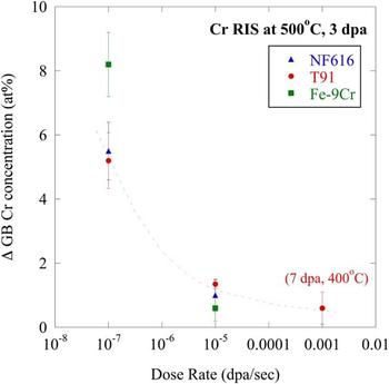
The CCSM collaboration utilized the Advanced Test Reactor National Scientific User Facility's pilot program to conduct fast neutron spectrum irradiations (∼10−7 dpa/s dose rate) of alloys of interest to the collaboration. These materials were from the same heats used in proton irradiations (∼10−5 dpa/s) throughout the collaboration. The collaboration also conducted 5.0 MeV Fe++ self-ion irradiations (∼10−3 dpa/s), producing specimens irradiated over three dose rates spanning four orders of magnitude. The neutron irradiations were conducted at a temperature of 500 °C to a dose of 3 dpa, so proton irradiations to these same conditions are used for comparison. Thus far, self-ion irradiations were only analyzed under conditions of 400 °C, 7 dpa.
The extent of Cr RIS decreases with increasing dose rate (Fig. 4), in T91, NF616, and Fe–9Cr model alloys. The difference in the magnitude of Cr RIS in T91 between proton and self-ion irradiations is ∼0.8 at.%. However, the difference between neutron and proton irradiations for all the three alloys studied is ≳4 at.%. This significant difference in RIS behavior between neutron and ion irradiations is attributed to differences in the damage cascade creation and morphology.
Dependence of Cr RIS on irradiation dose rate for NF616 and T91 irradiated with fast neutrons (∼10−7 dpa/s) and 2.0 MeV protons (∼10−5 dpa/s) at 500 °C to 3 dpa, and with 5.0 MeV Fe++ ions (∼10−3 dpa/s) at 400 °C to 7 dpa.

C. Understanding experimental observations through computational models
1. Grain boundary misorientation
To better understand the relationship between RIS and grain boundary misorientation, a computational model was designed to calculate RIS at specific grain boundary types in BCC steels. This model is an extension of the FCC steel models of Duh et al. Reference Duh, Kai, Chen and Wang36 and Sakaguchi et al., Reference Sakaguchi, Shibayama, Kinoshita and Takahashi37 and is a modified version of a RIS model for Ni–Cr alloys developed by Barnard et al. Reference Barnard, Tucker, Choudhury, Allen and Morgan30,Reference Barnard, Odette, Szlufarska and Morgan38 The theories of Wiedersich et al. Reference Wiedersich, Okamoto and Lam22 are used to develop a rate theory model, which solves the coupled diffusion equations for defect species and alloying elements' concentrations in one dimension, along their diffusion path toward the sink (i.e., grain boundary). A complete model description, including the derivation of boundary conditions, is provided in Ref. Reference Field, Barnard, Parish, Busby, Morgan and Allen33. The boundary condition alters the sink efficiency, thereby altering the point defect flux at the grain boundary. The model assumes that boundaries with high interfacial coherency, such as low-angle and low-Σ CSL boundaries, have low point defect capture efficiency under irradiation. As a result, point defect concentrations near a grain boundary are not constrained to the thermodynamic equilibrium.
Using these modified boundary conditions, the model reproduced the experimentally measured grain boundary misorientation dependence of Cr RIS within the range of uncertainty for both the experiment and the model. This good agreement between model and experiment has been demonstrated for an Fe–9Cr model alloy, irradiated with 2.0 MeV protons at 400 °C to 2 and 3 dpa Reference Field, Barnard, Parish, Busby, Morgan and Allen33 and with neutrons at 500 °C to 3 dpa. Reference Field, Miller, Chichester, Sridharan and Allen39 The model captures the cusp seen at the Σ3 orientation and near-asymptotic behavior of general high-angle grain boundaries (Fig. 5, for proton-irradiated Fe–9Cr, 3 dpa, 400 °C). These results can help explain other studies of FM steels in the literature, which observe variable RIS response for different grain boundary types, such as Ref. Reference Field, Miller, Chichester, Sridharan and Allen39. The strong dependence of RIS on grain boundary structure suggests that grain boundary engineering to modify the grain boundary orientation distribution could produce RIS-resistant steels.
Experimental (data points) and predicted (dashed line) grain boundary Cr concentration for a range of boundary misorientations under 3 dpa, 400 °C proton irradiation. Reprinted from Ref. Reference Field, Barnard, Parish, Busby, Morgan and Allen33.

Most importantly, this grain boundary structure model suggests that RIS in FM alloys can be understood to be a balance of vacancy- and interstitial-mediated diffusion. It therefore motivated a broader RIS modeling effort within the CCSM collaboration to computationally apply the defect diffusion-driven IK mechanism of RIS to FM alloys.
2. Inverse Kirkendall
An IK model is used to further understand the mechanisms of Cr RIS in bcc Fe–Cr binary alloys, across a range of times, temperatures, compositions, and dose rates. The grain boundary is simulated as an unbiased point defect sink. Wharry and Was Reference Wharry and Was35 used a one-dimensional IK model, which simultaneously solves a system of equations representing the concentrations of the major alloying elements and the point defects, as a function of space and time. These equations are solved across a plane foil, one surface of which is a symmetric grain boundary. Critical input parameters are the vacancy and migration energies of both Cr and Fe, which were determined from ab initio calculations. Modeled RIS composition profiles across grain boundaries were convoluted to provide a fair comparison with experimental measurements (which are convoluted by the STEM electron beam). Further details of the IK model, its inputs, and convolution, can be found in Refs. Reference Wharry and Was35 and Reference Penisten40.
The IK model was able to reproduce the experimentally measured temperature dependence of Cr RIS, within the known uncertainty range of the model input parameters. The IK model calculated RIS magnitudes almost identical to the measured RIS in proton-irradiated T91 to 3 dpa when the modeled dislocation density was input as 7.5 × 10¹⁴ m−2 (Fig. 6), which is consistent with the total sink strength of the material as measured in Ref. Reference Penisten40.
Temperature dependence of IK modeled Cr RIS for Fe–9Cr, compared with experimental measurements from 2.0 MeV proton-irradiated T91, at 3 dpa, 10−5 dpa/s.

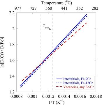
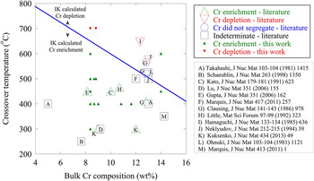
The IK model also predicted the crossover between Cr enrichment and Cr depletion between 600 and 700 °C. This crossover behavior can be explained by the diffusion coefficient ratios of Cr to Fe for both vacancies and interstitials (Fig. 7). The crossover occurs because the ratio of the vacancy diffusion coefficient in Cr to that in Fe crosses the ratio for interstitials, resulting in a change in Cr RIS direction. When the interstitial and vacancy diffusion coefficient ratios are equal (i.e., at the crossover), the contribution of Cr enrichment by interstitials is balanced by the contribution of Cr depletion by vacancies. Below the crossover temperature, Cr enrichment by interstitials dominates Cr depletion by vacancies, resulting in a net Cr enrichment. Conversely, above the crossover temperature, Cr depletion by vacancies dominates Cr enrichment by interstitials, resulting in a net Cr depletion. Furthermore, because the interstitial migration energies are dependent upon bulk composition, Reference Terentyev, Olsson, Klaver and Malerba41 the interstitial diffusion coefficient ratio of Cr to Fe will change with bulk Cr composition. This effect is illustrated in Fig. 7 for Fe–9Cr (solid line) and Fe–12Cr (short dashed line). Thus, increasing bulk Cr composition causes the crossover temperature to decrease.
Diffusion coefficient ratios of Cr to Fe for vacancies and interstitials in bcc Fe–Cr binary alloys. Crossover temperature, T cross, decreases for increasing bulk Cr content. Below T cross, Cr interstitial diffusion dominates, causing Cr enrichment. Above T cross, Cr vacancy diffusion dominates, resulting in Cr depletion.

The IK model suggests that the direction of Cr RIS is a function of both the temperature of irradiation and the bulk Cr content of the alloy. Thus, a plot of the crossover temperature can be used to identify whether a given FM alloy will exhibit Cr depletion or enrichment (Fig. 8). Observations of Cr enrichment should fall below the crossover temperature line, while observations of Cr depletion should fall above the crossover line. The majority of RIS measurements in the literature observed the direction of Cr RIS consistent with the IK model prediction (open triangles in Fig. 8). Two studies observed no Cr segregation (open circles); these studies have bulk Cr compositions and temperatures that fall close to the IK-predicted crossover line, which is reasonable. Several experiments were conducted using techniques that make it difficult to determine the true direction of Cr RIS (open squares). Measurements of Cr RIS collected through the CCSM collaboration are also shown (closed triangles). For the most part, the RIS measurements from the literature and the CCSM collaboration fall into good agreement with the crossover temperature based on the IK model.
Experimental measurements of the direction of Cr RIS in FM alloys, according to the literature (open symbols) and this work (closed symbols), as compared to the crossover temperature calculated in this work.

It should be noted that RIS measurements from the literature and the CCSM collaboration are taken predominantly in commercial alloys containing a number of minor elements. The IK model, however, only accounts for Fe and Cr. The effect of minor elements on the crossover temperature, and on Cr RIS behavior in general, is not well known. Nevertheless, the good agreement between experiment and model for the temperature dependence of RIS in T91, and consistencies between the RIS behaviors of Fe–9Cr model alloy and NF616, indicate that the effect of the minor elements may be minimal.
D. Relationship of RIS to precipitation
Because the CCSM collaboration included efforts to thoroughly study microstructural processes in irradiated FM alloys, effective comparisons can be drawn between RIS and irradiation-induced or -enhanced precipitation in the alloys studied. These comparisons can help to better understand the mechanisms of both phenomena.
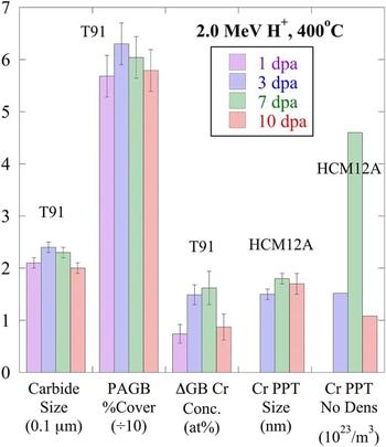
In the alloy T91 irradiated with 2.0 MeV protons at 400 °C over a range of doses between 1 and 10 dpa, the Cr RIS behavior Reference Wharry and Was34 exactly mirrors the evolution of prior austenite grain boundary (PAGB) carbides Reference Jiao, Shankar and Was42,Reference Wharry, Jiao, Shankar, Busby and Was43 (Fig. 9). In T91, the magnitude of Cr RIS increases between 1 and 7 dpa, then decreases from 7 to 10 dpa. Similarly, the average carbide size and the percent of the PAGB length covered by these carbides follow the same trend. The PAGB carbides are predominantly Cr-rich carbides with the M23C6 stoichiometry, Reference Jiao, Shankar and Was42 so it is reasonable that they exhibit consistent dose evolution as Cr RIS. In HCM12A irradiated under the same conditions, Cr-rich precipitates form in the alloy matrix, with their size and number density maximized at 7 dpa. Between 7 and 10 dpa, the Cr-rich precipitates undergo a decrease in both size and number density, consistent with the behavior of Cr RIS and PAGB carbides in T91 at the same doses. These results suggest that Cr from precipitates and grain boundaries may re-enter solution at elevated irradiation doses in FM alloys.
Comparison of irradiation dose evolution of carbides, Cr RIS, and Cr-rich precipitates in T91 and HCM12A irradiated with 2.0 MeV protons at 400 °C.

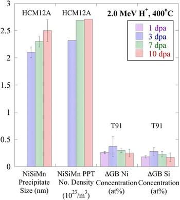
In HCM12A, nanoscale Ni–Si–Mn precipitates form in the matrix, on grain boundaries, and on dislocations and dislocation loops, following 2.0 MeV proton irradiation at 400 °C. Reference Jiao and Was44 These precipitates coarsen and continue to nucleate between 3 and 7 dpa, but between 7 and 10 dpa, their size and number density appear to reach a steady state. A similar dose evolution is observed for Ni and Si RIS in T91 irradiated to the same conditions – RIS increases up to about 3 dpa, then saturates at higher doses (Fig. 10). These results suggest that Si and Ni begin to leave solution at low doses, but the segregation and precipitation of Si and Ni ultimately reach a steady state, and the Si and Ni do not re-enter solution.
Comparison of irradiation dose evolution of Ni–Si–Mn precipitates, and Ni and Si RIS in T91 and HCM12A irradiated with 2.0 MeV protons at 400 °C.

The CCSM collaboration has contributed to a robust understanding of RIS in FM alloys. It has also afforded the opportunity to couple RIS measurements with precipitate characterization in identical heats of alloys, irradiated to identical conditions. The results of this project have provided a thorough understanding of the mechanisms and interrelationships of RIS and other microstructural processes in irradiated FM alloys.
III. RADIATION-INDUCED PRECIPITATION
Precipitation strengthening is one of the most effective strengthening mechanisms for conventional 9–12Cr steels. Reference Maloy, Toloczko, McClellan, Romero, Kohno, Garner, Kurtz and Kimura45 These strengthening phases (for instance, M23C6 and MX precipitates) are expected to be stable under service conditions so that the required strength can be retained. However, the pre-existing precipitates in F–M alloys may become unstable under irradiation. Jia and Dai Reference Jia and Dai46 found amorphization of M23C6 precipitates in T91 following irradiations at 110–205 °C, though the precipitates remained crystalline following irradiations at higher temperatures (250–360 °C). Irradiation also accelerates the precipitate coarsening in HT-9 and 9Cr–1Mo following irradiation at 400–550 °C. Reference Klueh and Harries17 Larger precipitates are observed following irradiations at 500 and 550 °C, indicating that coarsening kinetics increase with temperature as well. Reference Klueh, Shiba and Sokolov47
In addition to pre-existing precipitates, radiation-induced precipitates in F–M alloys may cause severe hardening and embrittlement and thus render the alloys unsuitable for advanced reactor applications. To date, Cr-rich α′-phase, Reference Gelles48–Reference Anderoglu, Van den Bosch, Hosemann, Stergar, Sencer and Bhattacharyya50 Si-rich G-phase, Reference Anderoglu, Van den Bosch, Hosemann, Stergar, Sencer and Bhattacharyya50,Reference Sencer, Kennedy, Cole, Maloy and Garner51 M6C and χ-phases, Reference Gelles48 σ-phase and the Fe2Mo type Laves phase have been reported in irradiated F–M alloys. The radiation-enhanced α′ phase can form through spinodal decomposition during thermal aging in high-Cr ferritic steels (>15 wt% Cr), but it has been observed in irradiated alloys with lower Cr content (12–13 wt%). However, α′ has not observed in 9Cr–1Mo (T91). Therefore, Gelles Reference Gelles48 suggested that there was a critical bulk Cr concentration (>12 wt%) for the formation of α′ precipitates.
G-phase was reported in HT9 and T91 irradiated to relatively high doses. Reference Klueh and Harries17,Reference Sencer, Kennedy, Cole, Maloy and Garner51 Early investigations showed extensive precipitation of G-phases in HT9 irradiated to 25–60 dpa at 400–425 °C in EBR II, and to 10 dpa at 300 and 400 °C in HFIR. Reference Klueh and Harries17 Sencer et al. Reference Sencer, Kennedy, Cole, Maloy and Garner51 recently confirmed the existence of the G-phase in HT9 irradiated to 155 dpa at 443 °C in FFTF. The G-phase particles were also observed in T91 irradiated to ≤39 dpa at 300–600 °C in HFIR, to 47 dpa at ∼400 °C in FFTF. Reference Sencer, Kennedy, Cole, Maloy and Garner51 In HT9 irradiated in the FFTF/MOTA at 420 °C to 200 dpa, G-phase precipitates of 10 nm in diameter are formed within laths, but larger sized G-phase particles are formed on PAGBs and packet boundaries. Reference Gelles48
Irradiation-induced phases other than the α′ and G phases were less frequently reported. The σ phase (an Fe–Cr phase) has been observed to form as large sheets and thin ribbons surrounding M23C6 particles in 9–13% Cr martensitic steels following irradiation at 420–460 °C in DFR. Reference Klueh and Harries17 The Laves (Fe2Mo type) phase is formed extensively during thermal aging in high-Cr martensitic steels. However, the formation of this phase is suppressed in T91 and HT9 during irradiation at temperatures in the range 300–615 °C. Reference Klueh and Harries17,Reference Klueh, Shiba and Sokolov47 Although various radiation-induced precipitates have been reported in F–M alloys, the evolution of the precipitates under irradiation is not well understood. Radiation-induced precipitates were mostly reported in isolated cases. Detailed characterization of the precipitates (both pre-existing and radiation-induced precipitates) such as the size, density, and composition is lacking. A systemic study of the evolution of the precipitates under neutron irradiation does not exist. However, proton irradiations, which can be performed under well-controlled conditions, provide an opportunity to conduct a more systematic study of phase stability and precipitation under irradiation. Furthermore, neutron-irradiated samples were characterized at relatively high doses (up to 200 dpa), where radiation-induced phases were well formed and they can be readily characterized using conventional TEM techniques. To understand the early nucleation/incubation stage of these new phases, irradiations need to be conducted at lower doses, which is ideal for proton irradiations. The application of relatively new technique of atom probe tomography enables us to study radiation-induced precipitates at early stages. Precipitate evolution at high dose (up to 500 dpa) will also be evaluated using high dose rate self-ion irradiations.
A. Irradiation conditions and precipitation observations
The compositions of HCM12A, T91, and HT9 used in this study are given in Table I. HCM12A was normalized at 1050 °C for 1 h and tempered at 770 °C for 45 min, T91 was normalized at 1066 °C for 46 min and tempered at 790 °C for 42 min, and HT9 was normalized at 1040 °C for 30 min and tempered at 760 °C for 60 min. The as-tempered alloys have prior austenite grain boundaries (PAGBs), packet boundaries, lath boundaries, and subgrain boundaries within the laths. Average prior austenite grain sizes are about 14 μm and laths are about 0.5–1 μm wide and several micrometers long. Bulky carbides cover PAGBs and packet boundaries and most of them are Cr23C6. Reference Jiao, Shankar and Was42
Samples were irradiated to 3, 7, and 10 dpa at 400 °C, and 7 dpa at 500 °C using 2 MeV protons and up to 500 dpa at 400 and 500 °C using 5 MeV Fe++. The temperature variation was monitored using a thermal imager and was kept within ±10 °C during the course of irradiation. A detailed procedure for proton irradiation can be found in Ref. Reference Gupta, Jiao, Ham, Busby and Was52. The dose rate was ∼10−5 dpa/s for proton irradiations and ∼10−3 dpa/s for Fe++ irradiations. The irradiation depths for 2 MeV protons and 5 MeV Fe++ are ∼20 μm and ∼1.2 μm, respectively, according to SRIM calculations. Reference Ziegler53 Characterization was performed at an irradiation depth of ∼7–10 μm for proton-irradiated samples and at a depth of ∼0.5–0.7 μm from the irradiated surface for Fe++ irradiated samples. These depths were selected to minimize the effect of surface and implanted ions.
Precipitate size and distribution at the PAGBs were studied in alloy T91 using a JEOL JSM-6480 scanning electron microscope (SEM) and JEOL 2010F analytical transmission electron microscope at the University of Michigan Electron Microbeam Analysis Laboratory (EMAL) in a complementary manner. For the samples irradiated at 400 °C for 3 and 10 dpa, SEM studies were carried out on TEM foils without further etching. Only the precipitates on PAGBs were considered for the analysis, which consisted of the percentage grain boundary coverage by the precipitates and size distribution of the precipitates. Precipitate size measurements were performed using a Java image processing program, Image J®. Approximately 150 µm grain boundary lengths covering about 400–500 precipitates were analyzed for each condition. Carbon film extraction replicas were produced from unirradiated material and from selected irradiated specimens. Both selected area electron diffraction pattern analysis and energy dispersive x-ray spectroscopy (EDS) were used for carbide identification. Changes in the microchemistry of the precipitates with temperature and dose were studied by analyzing at least 15 precipitates of one type under each experimental condition.
Atom probe tomography (APT) tips were prepared using the in situ lift-out method described by Mayer et al. Reference Mayer, Giannuzzi, Kamino and Michael54 using the focused-ion beam system. The tips were analyzed using the local electrode atom probe at the Central Analytical Facility of the University of Alabama. Either laser or voltage pulse mode was used depending on the mass resolution and the extended tails of major peaks (a possible indication of tip being heated up). The tips were kept at 40 K during the data acquisition. An evaporation rate of 0.01 atom/pulse was used in voltage pulse mode and the evaporation rate was higher for laser pulse mode.
Three-dimensional (3-D) reconstruction and precipitate analysis were done using the Imago Visualization and Analysis Software (IVAS) version 3.4. Maximum separation envelope method Reference Miller55 was used for precipitate analysis. The envelope method requires a proper selection of the maximum separation between the solutes in precipitates and the minimum number of atoms in the precipitates. Reference Vaumousse, Cerezo and Warren56 In this study, depending on the type of precipitate, the maximum separation (d max) varied between 0.35 and 0.7 nm and the minimum number of atoms (N min) in the precipitate was 100. The Guinier radius, which is equivalent to the radius of gyration for a homogeneous particle, was used to represent the size of particles. The volume fraction was derived from the precipitate size and number density assuming that the precipitate is spherical with a radius equal to the Guinier radius.
B. Precipitate response to irradiation at low doses
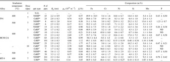
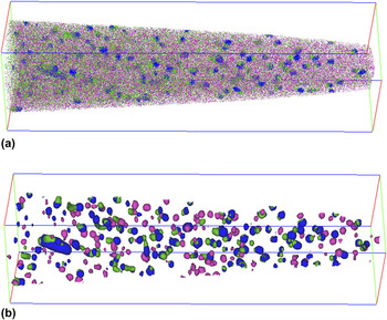
Three types of precipitates formed under irradiation were observed among the irradiated alloys; Ni/Si/Mn-rich precipitates (NSMPs), Cu-rich precipitates (CuRPs), and Cr-rich precipitates (CrRPs), depending on specific alloy and irradiation condition. Table III contains the precipitates observed along with their size, number density, volume fraction, and composition for all irradiation conditions described in this paper. Reference Jiao, Shankar and Was42,Reference Jiao and Was44 It is well known in the atom probe community that precipitate size and composition are dependent on the analysis parameters selected in IVAS. The data provided in the table are not taken as absolute values but rather used in a qualitative sense. Precipitates in F–M alloys are rather similar. In most cases of this paper, HCM12A at 400 °C and 7 dpa will be used as the reference. The reconstructed Ni (green), Cu (blue), and Cr (red) atom map in a volume of 250 nm × 63 nm × 63 nm of HCM12A irradiated with 2 MeV protons to 7 dpa at 400 °C represents the reference case and is shown in Fig. 11(a). Note that this sample contains all the three precipitates and they are best seen using isoconcentration plots (Ni, Cr, and Cu at ∼20 at.%) in Fig. 11(b), which highlights the precipitates. NSMPs, which are shown as green in Fig. 11(b), have a nominal composition of 11Ni–18Si–14Mn–0.7P in an Fe base and have a Guinier radius of 2.3 nm and a density of ∼2.7 × 10²³ m−3. Most also contain significant amounts of Cu, but this may be due to the close proximity of Cu-rich ppts that contain ∼28% Cu and are shown by the blue clusters in Fig. 8. The Cr-rich precipitates (in red) contain nearly equal amounts of Fe and Cr (48Fe–48Cr) and only very minor amounts of other elements. Again, the compositions provided should only be used as indicators of the major constitutes of the precipitates. Particularly for the significant amount of Fe presented in all precipitates, it is not only dependent on the parameters used but also could be a known artifact. It is therefore arguable whether the CuRPs and CrRPs are precursors of the α׳ and Cu phases, in which Cr and Cu contents should be close to 100%. However, as far as the NSMPs are concerned, they should be the precursors of the G-phase seen at high doses. The reasoning is that in G-phase (Mn6Ni16Si7), Ni is the dominant element with concentration at ∼55 at.%. Even only the three major elements are considered in NSMPs and assume that there is no Fe in the precipitates, Ni is only at ∼25% which is far below the concentration in G-phase.
Summary of experimental conditions for RIS investigations.

M = 2.0 MeV proton irradiation at MIBL.
W = 2.0 MeV proton irradiation at UWIBL.
A = fast neutron spectrum irradiation in ATR.
E = 5.0 MeV Ni++ irradiation at PNNL EMSL.
S = 5.0 MeV Fe++ irradiation at MIBL.
Precipitate size, number density, volume fraction, and composition as a function of irradiation condition [Jiao 2011, 2012]. N.O. indicates not observed.

APT image of a tip from HCM12A irradiated with 2 MeV protons to 7 dpa at 400 °C containing NSMPs, CuRPs, and CrRPs. (a) Ni (green), Cu (blue), and Cr (pink) atom maps. (b) NSMPs (green), CuRPs (blue), and CrRPs (pink) highlighted using isosurface plots. The dimensions of the box are 250 × 63 × 63 nm3.

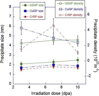
The dose dependence of the precipitate evolution in HCM12A at 400 °C between 3 and 10 dpa is shown in Fig. 12. NSMPs increase modestly in both size (from 2.1 to 2.5 nm) and density (from 2.3 × 10²³ m−3 to 2.7 × 10²³ m−3), resulting in an increase in volume fraction with dose. The Ni concentration of the NSMPs remains between 10 and 12 at.% across the dose range, but the Si, Mn, and P concentrations are at a maximum at 7 dpa. This could be due to the relatively small number of precipitates sampled and the selection of precipitates at different stages of evolution at these very low doses. Both Cu- and Cr-rich precipitates increase in size very little with dose. However, while the number density of Cu-rich ppts decreases steadily with dose, the Cr-rich precipitate number density appears to have a maximum at 7 dpa. The volume fraction for both Cu-rich and Cr-rich ppts peaks at 7 dpa. Neither Cu-rich nor Cr-rich ppts exhibit a systematic variation in composition with dose. Cu-rich ppts contain significant amounts of Cr, Ni, Si, and Mn, whereas Cr-rich ppts contain very little else. Nevertheless, all the three precipitates nucleate at the lowest dose (3 dpa) studied for HCM12A at 400 °C. One irradiation was conducted at 1 dpa in T91 at 400 °C and no precipitates were observed.
Dose dependence of precipitate size and number density in HCM12A irradiated with 2 MeV protons at 400 °C.

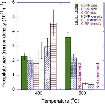
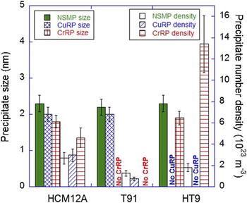
Figure 13 shows the temperature dependence of the precipitates in HCM12A irradiated with protons to 7 dpa. Note that at 400 °C, the size decreases in the order NSMP – Cu-rich – Cr-rich, and the density proceeds in the reverse order, which is not unexpected. Irradiation at 500 °C results in NSMP and Cu-rich ppts that are larger and at a lower density than that at 400 °C. The decrease in precipitate number density is most significant and is accompanied by a decrease in volume fraction with irradiation temperature. The most striking result is the lack of Cr-rich ppts at 500 °C. The composition varied with temperature as the NSMP at 400 °C contained larger concentrations of Ni, Si, Mn, and P than at 500 °C. The Cu concentration increased from 17.6 at.% at 400 °C to 30.2 at.% at 500 °C. The increase in Cu concentration may have contributed to the decrease in Ni, Si, Mn, and P concentrations in the NSMPs in HCM12A. The Cu content of the Cu-rich precipitate was close to 60% higher in the precipitate formed at 500 °C versus that at 400 °C.
Temperature dependence of precipitate size and number density in HCM12A irradiated with 2 MeV protons to 7 dpa.

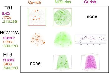
NSMPs are observed in all the alloys, due to sufficient bulk concentrations of Ni and Si. Cu-rich ppts are observed in HCM12A and T91 but not in HT9, and Cr-rich ppts are observed in HCM12A and HT9, but not in T91 (Fig. 14). Inspection of the bulk compositions of the alloys shows that indeed, the Cu content is much lower in HT9 compared to the other two alloys. Since T91 is a 9Cr alloy and HCM12A and HT9 are nominally 12Cr alloys, the absence of a Cr-rich ppt in T91 is not unexpected. Figure 15 shows a pictorial representation of the occurrence of each type of precipitate in each alloy and the corresponding composition of that alloy.
Alloy dependence of precipitate size and number density following irradiation with 2 MeV protons to 7 dpa at 400 °C.

Distribution of Cu-rich, Ni/Si/Mn-rich, and Cr-rich precipitates in T91, HCM121A, and HT-9 following irradiation to 7 dpa at 400 °C. The concentrations of Cr, Cu, Ni, and Si are also listed.

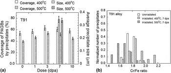
Pre-existing phases in unirradiated T91 alloy consisted of M23C6 carbide and MX type precipitates. Coarse (0.1–0.3 μm length) M23C6 precipitates were located on PAGBs and on subgrain boundaries and were rich in Cr and Fe and with traces of Mo and V. Finer (20–50 nm size) MX particles were found within subgrains and also near the PAGBs and were rich in V and Nb and also contained Cr and Fe. Contrary to the M23C6 type precipitates, there was a large variation in the amount of V and Nb in these alloys that is consistent with the previous report that these might be forming at various stages of tempering treatment. Reference Homolová, Janovec, Záhumenský and Výrostková57 The precipitate size distribution on PAGBs was studied for proton doses of 1, 3, 7, and 10 dpa at 400 °C and 7 dpa at 500 °C, and is reported in detail in Ref. Reference Jiao, Shankar and Was42, and summarized here for completeness. At 400 °C, for doses up to 3 dpa, both precipitate size and grain boundary coverage increased, but between 3 and 10 dpa, these parameters remain approximately constant or decrease slightly, as shown in Fig. 16(a). It is observed that for 7 dpa at 500 °C, both the average size of the PAGB precipitates and the grain boundary coverage increased compared to 7 dpa at 400 °C. Precipitate growth and increased boundary coverage upon irradiation at high doses and temperature close to 500 °C has been reported in PNC-FMS steel Reference Yamashita, Yano, Tachi and Akasaka58 suggesting that irradiation enhanced the growth of precipitates due to irradiation-assisted diffusion.
Effect of dose and irradiation temperature on (a) grain boundary precipitate size and percentage coverage on PAGBs for T91 alloy irradiated at 400 and 500 °C, and (b) relative change (with respect to the unirradiated condition) in the concentration ratios Cr/Fe of M23C6 precipitates present at the PAGBs of alloy T91 following irradiation to 7 dpa at 400 °C and 500 °C.

EDS maps from secondary phases on a carbon extraction replica taken from alloy T91 irradiated at 400 °C for 7 dpa clearly indicate coexistence of Cr, Fe, Mo in the larger M23C6. Fine V and Nb rich precipitates are clearly observed in the same vicinity. A few large Nb and V rich precipitates were also observed. The coexistence of fine (V, Nb) rich precipitates and M23C6 is in line with that reported by Abe et al. Reference Abe, Horiuchi, Taneike and Sawada59 The M23C6 precipitates in the T91 specimen irradiated at 400 °C for 7 dpa showed a slight increase in Cr/Fe, Mo/Fe, and Mo/Cr ratios compared to the unirradiated condition. The increase in the Cr/Fe ratio is shown in Fig. 16(b) as the distribution of the concentration ratios slightly shifts to the right (high ratios). However, a decrease in Cr/Fe, and an increase in the Mo/Fe and Mo/Cr ratios were observed for the sample irradiated at 500 °C for 7 dpa. It should be noted that enrichment and depletion of Cr and Fe have been observed at the grain boundary regions of the matrix free from precipitates in thin foils obtained from the specimens irradiated at these two temperatures. Reference Wharry, Jiao, Shankar, Busby and Was43 Hence, it may be some interdependence of solute enrichment/depletion at PAGBs and the change in Cr/Fe composition of grain boundary precipitates.
Two types of precipitates of different chemical compositions were observed. One with Cr/Fe ratio between 2 and 2.2 (Type I) and the other with a Cr/Fe ratio between 3.4 and 3.6 (Type II). In Fe–9Cr steel, both M23C6 and M7C3 precipitates have been reported to occur simultaneously. Reference Abe, Noda and Okada60 M7C3 is reported to form only in 9Cr steel without W, V, or Mo and becomes unstable by the addition of W, V, or Mo. Reference Abe, Noda and Okada60 Upon irradiation at 400 °C, an increase in the Cr/Fe ratio is observed in both types of precipitates. Hence, the similarity in the increase of the Cr/Fe ratio in the carbides at 400 °C for both T91 and the 9Cr model alloy indicates that the presence of other elements in T91 does not affect the evolution of the composition of these phases.
1. Precipitate response to irradiation at high doses
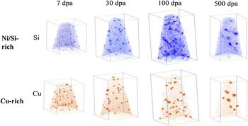
Irradiation doses up to 500 dpa were conducted using 5 MeV Fe++. Figure 17 shows the evolution of Ni/Si/Mn-rich and Cu-rich precipitates with dose in HCM12A following Fe++ irradiated at 400 °C. Clustering of Ni/Si starts to occur at 7 dpa, indicating that an incubation dose of ∼7 dpa may exist for Ni/Si/Mn-rich precipitates. For proton irradiation, the incubation dose appears to be between 1 and 3 dpa. The difference in incubation dose may be related to the difference in dose rate and cascade size. The dose rate for self-ion irradiations is about two orders of magnitude higher than that for proton irradiations. Ni/Si/Mn-rich precipitates appear at 30 dpa and there is virtually no change up to 100 dpa. Slight coarsening occurs at very high dose of 500 dpa. Incubation dose for Cu-rich precipitates apparently is dependent on bulk composition. They appear at 7 dpa for HCM12A with high Cu content and 30 dpa for T91 with low Cu content. Also the coarsening process for HCM12A occurs at a low dose of <30 dpa while the coarsening process for T91 is not obvious even at 500 dpa. The density of Cr-rich precipitates is generally low and a clear trend of evolution with dose was not seen. The nucleation sites of Cr-rich precipitates are independent of the other two types of precipitates. The effect of irradiation temperature on precipitate size and density is very predictable with larger precipitates at lower density at higher temperature. Precipitates are evidently larger and at lower density at 500 °C compared to those at 400 °C at 100 dpa for both Ni/Si/Mn-rich and Cu-rich precipitates. The temperature effect on precipitate size and density at high dose by Fe++ is similar to that at low doses by protons.
Evolution of Ni/Si/Mn-rich and Cu-rich precipitates with dose in HCM12A following Fe++ irradiated at 400 °C.

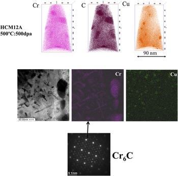
Irradiation at high temperature to high dose (500 °C: 500 dpa) results in the formation of Cr6C as shown in Fig. 18 from the APT atom maps and from TEM/EDS and diffraction patterns in HCM12A. Formation of Cr6C is probably due to the dissolution of pre-existing Cr23C6 as suggested by Maziasz et al. Reference Bloom, Busby, Duty, Maziasz, McGreevy, Nelson, Pint, Tortorelli and Zinkle8 At this extreme condition, partial dissolution of Cu-rich precipitates may occur leading to the smaller volume fraction of Cu-rich precipitates at 500 dpa than that at 100 dpa. Further coarsening of Ni/Si/Mn-rich precipitates at 500 dpa leads to a very low number density that may be missed by the limited examined area.
Formation of M6C carbides in HCM12A following Fe++ irradiation to 500 dpa at 500 °C.

C. Summary of radiation-induced precipitation observations
-
1. Three types of precipitates (Ni/Si/Mn-rich, Cu-rich, and Cr-rich) were observed in both proton- and self-ion-irradiated F–M alloys. Whether one will form depending upon alloy composition and the irradiation temperature.
-
2. An incubation dose exists for Ni/Si/Mn-rich precipitates for both proton and self-ion irradiations. In proton irradiation, the incubation dose appears to be greater than 1 dpa while it is around 7 dpa in self-ion irradiation. The difference in incubation dose may be related to the large differences in dose rate and cascade size.
-
3. Precipitates evolve slowly with dose and do not show a strong or consistent dependence on irradiation dose at low doses. Precipitate coarsening occurs at high doses.
-
4. High irradiation temperature results in larger precipitates at lower density for both low and high doses.
-
5. Pre-existing carbides can be modified by proton irradiation at low doses and new carbides may form at high doses.
IV. STABILITY OF OXIDE NANOCLUSTERS UNDER IRRADIATION
NFAs currently under development for higher temperature, high dose radiation service have a fine dispersion of Y–Ti–O nanoparticles that provide enhanced tensile and creep strength and possibly resistance to radiation damage. Reference Odette, Alinger and Wirth18,Reference Odette and Hoelzer61–Reference Ukai, Mizuta, Fujiwara, Okuda and Kobayashi63 NFAs are ferritic stainless steels that typically contain between 12 and 20% Cr, and are dispersion strengthened with a very high density of ultrafine Y–Ti–O enriched nanoparticles. Reference Odette, Alinger and Wirth18 NFAs, as well as more traditional ODS steels, are usually processed from elemental or pre-alloyed metal powders mechanically alloyed with oxide powders (typically Y2O3) in an attritor or ball mill. This is followed by consolidation by hot isostatic pressing or hot extrusion often resulting in anisotropic grain morphology (elongated grains in the extrusion direction). The precipitate dispersion in the as-fabricated materials is characterized by a wide size distribution including very small particles (<5 nm diameter) whose chemical composition and crystallographic structure remain open questions, as discussed in more detail below, and larger particles up to several hundred nanometers in size (depending on the alloy). It is now commonly accepted that the initial Y2O3 oxides dissolve during the mechanical alloying phase and precipitation of the Y–Ti–O nanoparticles occurs during consolidation. Reference Odette, Alinger and Wirth18 Recent ODS steel variants developed in national laboratories have different chemical compositions for improving corrosion resistance or for reducing activation (e.g., substitution of Mo with W). Better control on grain size and morphology, dispersion size distribution, and spatial distribution, and better mechanical properties have been achieved, however the characterization and the stability of the nanodispersion both in the as-processed state, as well as following high-dose irradiation remain uncertain.
The structure and composition of the 2–3 nm particles, which seem essential to the excellent mechanical properties, have been characterized by energy filtered TEM, Reference Odette and Hoelzer61,Reference Hoelzer, Bentley, Sokolov, Miller, Odette and Alinger64 small angle neutron scattering, Reference Odette, Alinger and Wirth18,Reference Alinger, Odette and Hoelzer65 and APT. Reference Miller, Hoelzer, Kenik and Russell66,Reference Marquis67 As well, fundamental modeling has been used to evaluate the possible precipitate cluster arrangements and compositions. Reference Barnard, Odette, Szlufarska and Morgan38,Reference Alinger, Wirth, Lee and Odette68–Reference Demkowicz, Bellon and Wirth70 These characterization methods generally agree on the existence of a very high density of 2–3 nm diameter particles that are enriched in Y–Ti–O, but do not agree on the composition or even the structure of the nanoparticles. Atom probe tomography studies by Miller and coworkers Reference Miller, Hoelzer, Kenik and Russell66 have shown that these smaller particles consist mainly of nonstoichiometric “clusters” of these atoms. Particles at larger sizes, with diameters of about 5 nm, have been observed that coincide with the known stoichiometric oxides, Y2Ti2O7 and Y2TiO5. Reference Odette and Hoelzer61 However, the composition of the particles and how composition may vary with size are not clearly understood.
Odette and coworkers believe that the pyrochlore structure and composition (Y2Ti2O7) persist at the smaller, 2–3 nm diameter and smaller particles as well. Whereas, Brandes and coworkers argue on the basis of modeling the creep response of 14YWT Reference Brandes, Kovarik, Miller, Daehn and Mills71 that the particle should have a structure distinct with the matrix, and that the interfacial structure is significantly strain relaxed and possibly incoherent, or that the precipitates need to have lower elastic moduli than the matrix. Modeling studies have either focused on the very few atomic size building blocks of the precipitates, Reference Jiang, Smith and Odette69,Reference Fu, Krčmar, Painter and Chen72 or assumed that the precipitates are lattice matched and coherent Reference Alinger, Wirth, Lee and Odette68,Reference Demkowicz, Bellon and Wirth70 or substituted TiO2, Y2O3, and mixed oxides in semicoherent structural units, Reference Barnard, Odette, Szlufarska and Morgan38 but consensus on the structure and composition remains lacking and the overall topic of the nanoprecipitate composition and structure remains a very active area of research both experimentally and computationally. Furthermore, the nanoparticle distributions are often quite heterogeneous. Reference Odette, Alinger and Wirth18,Reference Miller55,Reference Odette and Hoelzer61,Reference Hoelzer, Bentley, Sokolov, Miller, Odette and Alinger64–Reference Marquis67 Recent modeling work Reference Barnard, Odette, Szlufarska and Morgan38 has suggested that the precipitates are thermodynamically most stable as nearly stoichiometric oxides with structures essentially identical to their bulk oxide structures, even down to just tens of atoms. While these results await full experimental validation, Ribis and de Carlan Reference Ribis and de Carlan73 recently observed Y2Ti2O7 particles in the range of 2–6 nm that are identical in structure and orientation within the Fe lattice to the Ti–Y–O particles predicted by the first principles calculations of Barnard et al. Thus, while it is generally agreed that the Y–Ti–O nanoparticles have compositions that are different from the equilibrium bulk oxides of Y2Ti2O7 and Y2TiO5, Reference Odette, Alinger and Wirth18 detailed information about the composition, structure, and the dependence with size is currently not known. Likewise, the stability of the precipitates under irradiation and high temperatures is not well understood.
The literature on Y–Ti–O nanoparticle stability under neutron irradiation is scarce and coworkers have reported that precipitates in alloy DY, a 13%Cr ODS alloy produced by SCK CEN in Belgium for potential reactor application, can undergo dissolution and reduction in average size under neutron irradiation. Reference Dubuisson, Gilbon and Séran49 Monnet and coworkers showed that dissolution of some precipitates in the DY alloy also occurs under ion irradiation at high doses. Reference Monnet, Dubuisson, Serruys, Ruault, Kaïtasov and Jouffrey74 Likewise, Allen and coworkers found that nickel ion irradiation in the temperature range of 500–700 °C to doses from 5 to 150 dpa resulted in a decrease in the nanoparticle size in an Fe–9%Cr ODS alloy. Reference Allen, Gan, Cole, Miller, Busby, Shutthanandan and Thevuthasan75 Other studies have indicated that the nanoparticle size distributions were stable and that the size distribution was essentially unchanged for low dose ion irradiation up to 20 dpa at temperatures between 200 and 650 °C. Reference Certain, Field, Allen, Miller, Bentley and Busby76–Reference Pareige, Miller, Stoller, Hoelzer, Cadel and Radiguet79 Gelles found that nanoscale dispersoids in MA957 were stable under neutron irradiation at 425 °C to doses up to 200 dpa. Reference Gelles48
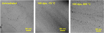
More recently, Lescoat and coworkers have used in situ TEM study of nanoparticle stability during 150 keV Fe ion irradiation. Reference Lescoat, Ribis, Gentils, Kaïtasov, de Carlan and Legris80 This controlled experimental study demonstrated the ability to follow the irradiation response of the same region of an Fe–18%Cr NFA up to 45 dpa at 500 °C, and did not identify any significant evolution of the nanoparticles with sizes in the range of 5 nm. Reference Lescoat, Ribis, Gentils, Kaïtasov, de Carlan and Legris80 Likewise, Certain and coworkers have undertaken a systematic heavy-ion irradiation study on 14YWT using 5 MeV nickel ions over the temperature range of −75° to 600 °C, Reference Certain, Kuchibhatla, Shutthanandan, Hoelzer and Allen81,Reference Certain, Lee Voigt, Allen and Wirth82 which were then characterized by energy-filtered TEM and atom probe tomography. This study clearly indicates that ballistic re-solution processes (forcing the elements back into solution) do occur, with irradiation at −75 °C to 100 dpa revealing an almost complete absence of the Y–Ti–O nanoparticles. Figure 19 shows the Fe–M jump-ratio images obtained from the energy filtered TEM analysis of the unirradiated 14YWT control material, as well as following Ni heavy ion irradiation to 100 dpa at −75 and 600 °C, respectively. Whereas irradiation at −75 °C to 100 dpa resulted in the dissolution of the nanoparticles, irradiation at 600 °C to 100 dpa reveals a similar size distribution and number density to the unirradiated control sample. Reference Certain, Kuchibhatla, Shutthanandan, Hoelzer and Allen81,Reference Certain, Lee Voigt, Allen and Wirth82 In a more recent study by Lescoat et al., Reference Lescoat, Ribis, Chen, Marquis, Bordas and Trocellier83 ODS steels were irradiated using Fe ions at 500 °C up to 150 dpa; the nano-oxide population evolution under irradiation was found to be similar to that observed after annealing at high temperature, i.e., a slight increase in the particle size and a slight decrease in the density were observed, which were both explained by an Ostwald ripening mechanism.
Set of Fe–M jump-ratio images from a control 14YWT sample, and 14YWT samples irradiated to 100 dpa at temperatures ranging from −75 to 600 °C. The darker areas correspond to the nanoclusters.

The clear conclusion from these studies is that significant uncertainty remains in characterizing the precise character (structure and composition) of the Y–Ti–O nanoparticles, as well as the size evolution of the nanoparticles under energetic particle irradiation. Although, ballistic re-solution of the Y–Ti–O nanoparticles is clearly observed at very low temperatures, a full understanding of the fate of the re-solved atoms, including the subsequent diffusion back to the nanoparticle or to nucleating similar precipitate clusters remains elusive. Part of that uncertainty may come from the heterogeneous particle size and density distributions in the as-consolidated condition, the study of different alloys with different nanoparticle compositions, or from the fact that there are likely many different types of nanoparticles, in terms of size and composition even within a single alloy. Further studies are required to better understand the different types of Y–Ti–O nanoparticles, as well as the stability of these particles under irradiation.
V. MICROSTRUCTURE EVOLUTION UNDER IN SITU ION IRRADIATION
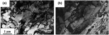
The chemical composition of NF616 (ASTM Code: P92) and 9Cr-model alloys is given in Table I. The model alloy with similar Fe, Cr, and C content as NF616 was fabricated at Ames Laboratory by arc melting of high purity elements. Details of the processing of the alloys can be found elsewhere. Reference Kaoumi and Adamson85–Reference Topbasi, Motta and Kirk87 Electron transparent samples of NF616 and model alloy “9Cr-model” were prepared by electropolishing using a solution of 95% methanol and 5% perchloric acid. NF616 exhibits the tempered martensite structure typically observed in 9–12Cr F–M steels, with lath structures inside the large prior austenite grains, and a high density of M23C6 and M(C,N) precipitates are present along lath boundaries and prior austenite boundaries. Reference Ennis, Zielinska-Lipiec, Wachter and Czyrska-Filemonowicz88 As shown in Fig. 20, the microstructure of the model alloy replicates reasonably well the microstructure of NF616 in terms of lath/subgrain; however, the density of precipitates appears to be lower in the model alloy due to the lower concentration of carbide stabilizers in this alloy.
Bright-field TEM images of the lath structure inside prior-austenite grains of (a) NF616 and (b) 9Cr-model alloys.

The TEM samples were irradiated in situ at the intermediate voltage electron microscope at Argonne National Laboratory at a range of temperatures (from −223 to 400 °C), with 1 MeV Kr ions, at a typical current of 0.5 × 10¹² ions cm−2 s−1 resulting in an estimated dose rate of 1.4 × 10⁻³ dpa/s (averaged over the foil thickness), calculated using the full cascade mode of the SRIM Monte Carlo code Reference Ziegler84 with displacement energies of 40 eV for Fe and Cr and 28 eV for C. Reference Kaoumi and Adamson85,Reference Topbasi, Motta and Kirk87 The microstructure evolution under irradiation was followed and characterized at successive doses in terms of defect formation and evolution using weak-beam dark-field imaging by exciting (110) reflections. During the in situ experiments, selected areas in the samples were followed throughout the irradiations, which allowed accurate measurements of number density and size distribution of defects as a function of dose in the same areas. In addition, video recording was performed with a coupled camera during irradiation for subsequent frame-by-frame analysis.
A. Observations of irradiation-induced microstructure evolution
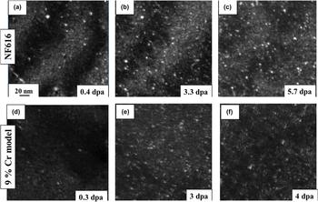
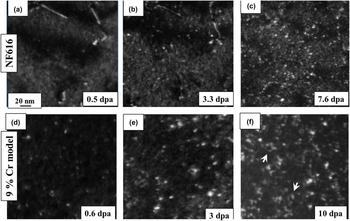
Figure 21 shows a series of dark-field TEM images taken at successive doses of NF616 and 9Cr-model alloys irradiated at −223 °C. At this temperature, the microstructural evolutions of NF616 and the 9Cr-model alloys were quite similar at low doses: both alloys exhibited a threshold dose below which no defects are seen and above which small defect clusters become visible. The defect clusters appeared as small white dots that gradually increase in density until an apparent saturation was observed, more or less homogeneously throughout the sample. Also, a significant fraction of defect clusters in NF616 and the 9Cr-model alloys exhibited sudden jumps under the ion beam over a few nanometers even at −223 °C.
Dark-field TEM images of microstructure evolution of NF616 under 1 MeV Kr irradiation at −223 °C.

Figure 22 illustrates the evolution of the irradiation-induced microstructures in NF616 and 9Cr-model alloys when irradiated at 200 °C. Reference Topbasi, Kaoumi and Motta89 The microstructure development in NF616 under irradiation at −223 and 200 °C was quite similar. After a threshold dose, the defect clusters became visible and their density started to increase until saturation with no apparent change in the size of defect clusters. In contrast, the average diameter of defect clusters in the 9Cr-model alloy increased with dose Reference Kaoumi and Adamson85 likely by absorption of point defects and resolvable loops started to become visible in the 9Cr-model alloy around 2–3 dpa and interaction of these loops (at this temperature) resulted in the formation of dislocation tangles at higher doses, as shown in Fig. 22. Interaction of the irradiation-induced defects with the pre-existing lath boundaries was observed in the 9Cr-model alloy (as evidenced by the formation of denuded zones) Reference Kaoumi and Adamson85 but not in NF616. No voids or irradiation-induced precipitates were observed in either alloy for the irradiation temperatures and doses studied.
Dark-field TEM images of microstructure evolution of NF616 under 1 MeV Kr irradiation at 200 °C.

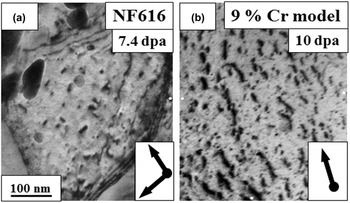
At the higher doses (above 5 dpa), self-ordering of defect clusters in some grains in NF616 at 400 °C resulted in the formation of the vertically aligned defects as shown by the arrows in Fig. 23(a) which shows the NF616 alloy after irradiation to 7.4 dpa at 400 °C. Reference Topbasi, Kaoumi and Motta89 Similarly aligned defect structures were reported to form in binary in pure Fe and Fe–8%Cr alloys under heavy-ion irradiation at 500 °C. Reference Jenkins, Yao, Hernández-Mayoral and Kirk90,Reference Hernández-Mayoral, Yao, Jenkins and Kirk91 Self-ordered defect structures were also observed in the 9Cr-model alloy only at the lower temperatures (25 °C and below) as seen in Fig. 23(b). The defect arrays were approximately aligned with the <110> directions with a spacing of about 30–50 nm. This phenomenon of self-ordering of defects in the 9Cr-model alloy was described and discussed in detail in Ref. Reference Kaoumi, Adamson and Kirk86. This structure is thought to result from elastic interactions between defect clusters in the foil. The stress caused by a high density of loops would be minimized by the regular arrangement of defects clusters and the preferred crystallographic orientation of defect arrays would be driven by the minimization of elastic interaction energy between defect clusters. The fact that this alignment of small defect clusters was observed at high doses in the 9Cr-model alloy for irradiations conducted between −223 and 25 °C, whereas they started to form in NF616 only at 400 °C indicates that not only a high density of defects is necessary but also migration.
Bright-field transmission electron micrographs of extended defects observed in NF616 and 9Cr-model alloys under 1 MeV Kr irradiations performed at 400 °C (a) and 25 °C (b), respectively. Reference Topbasi, Kaoumi and Motta89

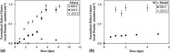
Quantitatively, the defect cluster density was measured as a function of dose for all temperatures and defect density values were normalized to the highest value acquired for each alloy, plus the error bar. Figure 24 shows the normalized defect cluster density versus dose for NF616 at −223, 200, and 300 °C to 8 dpa and for the 9Cr-model alloy at −223 and 200 °C to 5 dpa. The measured defect cluster density in NF616 appears to saturate at ∼6 dpa, while it saturates at a much earlier dose in the 9Cr-model alloy. The defect cluster density in both alloys decreased with increasing temperature. There appears to be a more pronounced effect of temperature in the model alloy than for the NF616 alloy: between −223 and 200 °C the decrease in saturation density of NF616 was ∼10% while for the 9Cr-model alloys showed a decrease of ∼70%, in its saturation defect cluster density. In NF616, the irradiation at 400 °C shows a large decrease in defect cluster density, suggesting the onset of a thermally driven regime at that temperature. This onset of thermally driven regime was seen already at 200 °C for the 9Cr-model alloy.
Normalized defect cluster areal density of (a) NF616 and (b) 9Cr-model alloys as a function of dose. The defect cluster density is normalized to the highest value acquired (5.5 dpa at −223 °C for NF616 and 2 dpa at −223 °C for 9Cr-model alloy), plus the error bar. Reference Topbasi, Kaoumi and Motta89

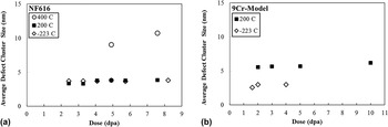
Figure 25 shows the average defect cluster size versus dose in NF616 at −223, 200, and 400 °C. It is clear that the defect size does not change with either dose or temperature, except at 400 °C. Reference Topbasi, Kaoumi and Motta89 The average defect size in NF616 was around 3–4 nm at −223 and 200 °C, while it almost doubled at 200 °C. On the other hand, for the 9Cr model alloy, the average defect size was 35–38% larger at 200 °C than that measured for the irradiation at −223 °C. Reference Kaoumi and Adamson85
Average defect cluster size of (a) NF616 and (b) 9Cr-model alloys as a function of dose. Reference Topbasi, Kaoumi and Motta89

B. Discussion
1. Defect formation and visibility
The in situ experiments allowed for dynamic observations of defect cluster appearance (i.e., appearance of a white dot in dark-field mode) and sometimes disappearance during irradiation. This dynamic appearance and disappearance of defect clusters continued after a defect saturation was visibly reached for each temperature. The dynamic observations of defect cluster appearance and disappearance suggest that the formation of visible defect clusters is caused by a cascade-driven process, in which defect clusters can be formed within cascades or by cascade overlap. The collapse of individual, isolated cascades to visible defects in Fe did not occur under heavy-ion irradiations, however, visible damage was observed at relatively high irradiation doses. Reference Fukushima, Shimomura and Yoshida92–Reference Yao, Hernández-Mayoral, Jenkins and Kirk94 At cryogenic temperatures (−223 °C), irradiation-induced defect clusters did not become visible until higher doses (∼0.3 dpa at the earliest for the 9Cr-model alloy) compared to irradiations conducted at higher temperatures (∼0.07 dpa in the same alloy). Reference Kaoumi, Adamson and Kirk86 This suggests that at the lowest temperatures a large density of small defects under the resolution limit are formed at low doses and become visible/detectable only when high-enough doses are reached allowing for the clusters to grow to a size larger than the TEM resolution limit, by cascade induced defect cluster motion or direct overlap.
2. Defect motion/jumps
Flickering and sudden jumps of white dots in DF-TEM images were observed early on during the irradiations even at cryogenic temperatures down to −223 °C. The one-dimensional jumps of clusters were observed in both alloys. Experimental studies Reference Hernández-Mayoral, Yao, Jenkins and Kirk91,Reference Arakawa, Ono, Isshiki, Mimura, Uchikoshi and Mori95 and molecular dynamics (MD) simulations Reference Wirth, Odette, Maroudas and Lucas96 have confirmed that SIA clusters are able to move one-dimensionally, along some particular crystallographic orientation. The 1D migration behavior of interstitial clusters has been reported for pure metals and alloys under electron irradiation, ion irradiation, and annealing after electron irradiation. In bcc metals, this 1D migration is usually along the close packing directions of <111>, consistent with the results of the MD simulations.
“To-and-from hops” of clusters (i.e., sudden back and forth (1D) movements about the same position) often observed in ultrahigh purity iron systems were more rarely seen in these more complex alloys and the defect jumps had a smaller rattling frequency. Also, the jump distances in the current alloys were less than the jumps observed by others in pure iron. Reference Hernández-Mayoral, Yao, Jenkins and Kirk91 When such cluster hops occurred during irradiation, the cluster could spend a few seconds before jumping back to the previous position, suggesting that impurity trapping slows down the motion. Also, during the cryogenic experiments, cluster jumps were observed but the motion would stop as soon as the ion beam was turned off. The fact that these jumps only happened when the ion beam was on suggests that the jumps are not driven by diffusion but may rather be due to cascade interactions, i.e., the overlapping of defect cascade created under the ion impact. Two theoretical mechanisms could explain this phenomenon Reference Kaoumi, Adamson and Kirk86 : (i) solute and impurity atoms pin down SIA clusters to prevent 1D motion and during irradiation if a cascade displaces the solute atom then the SIA cluster can migrate until it is pinned again by another solute or impurity atom; or (ii) the cascade may induce a shock wave that changes the strain fields around the pinned SIA cluster causing it to migrate until the energy is dissipated or it is pinned again by another solute atom. Reference Wirth, Odette, Maroudas and Lucas96
3. Defect density/size dependence on dose
The areal density of the TEM-visible defect clusters increased with dose, approaching an apparent dynamic saturation, in which defects are constantly created and destroyed at the same rate. Reference Topbasi, Motta and Kirk87 The constant saturation defect size in NF616 between −223 and 200 °C indicates a significant reduction in the mobility of defects preventing the clusters/loops from getting larger in this wide temperature range, likely due to impurity trapping. On the other hand, the decrease in the density of defects between −223 and 200 °C was more pronounced in the 9Cr-model alloy compared to NF616. In addition, growth of loops is observed in the model alloy at 200 °C. This can be attributed to the higher mobility of defects in the model alloy which can result in a higher rate of recombination and defect loss to the sinks, or participation to loop growth.
The dose dependence of the average loop size (as well as the loop density) is expected to be affected by the mechanisms of loop growth at play, Reference Kaoumi and Adamson85 i.e., whether loop growth happens by (i) diffusion and absorption of single point defects, (ii) by diffusion and absorption of smaller clusters, (iii) by cascade overlap, or (iv) by loop coalescence. In contrast with what is seen in pure Fe, loop coalescence was not observed in either alloy likely because of reduced mobility of loops by impurity trapping; however, small black dots were seen decorating larger loops in the 9Cr-model alloy suggesting that the larger loops can grow by absorption of smaller clusters and point defects. Reference Kaoumi and Adamson85 These can be small clusters formed in the direct vicinity of the loops, either swept there by cascade impact at the lowest temperatures or by thermal migration at the highest temperatures above stage II.
The differences in the microstructural evolution of NF616 and 9Cr-model alloys including the effect of temperature on average defect size and defect density could be explained within the framework of the trapping of defects by solute atoms, due to the difference in solute concentration between the two alloys. Reference Topbasi, Kaoumi and Motta89 MD simulations Reference Bacon, Osetsky, Stoller and Voskoboinikov97–Reference Wirth99 showed that interstitial and substitutional point defects and their clusters can form directly in cascades and interstitial defect clusters (<100 member) diffuse with activation energies comparable to one of single self-interstitials in the absence of solute atoms by exhibiting a collective motion of interstitial crowdions. Reference Cottrell and Bilby101 However, the presence of solute atoms in NF616 and 9Cr-model alloys may strongly affect their mobility and control processes such as loop growth and migration to sinks. The concentration of alloying elements in NF616 is considerably higher than in the 9Cr-model alloy. Although a fraction of these solute atoms precipitate as carbides and other particles at lath and prior austenite boundaries in NF616 during the tempering treatment, a fraction of these alloying elements remain in the matrix and pin dislocations or reduce the mobility of defect clusters. Reference Cottrell and Bilby101 A higher density of solute atoms in the matrix of NF616 can trap irradiation-induced defects once they are created thus explaining the shorter length of defect jumps in NF616 than in 9Cr-model alloy (which were in turn found to be shorter than those seen during irradiation of pure Fe Reference Hernández-Mayoral, Yao, Jenkins and Kirk91 ), and the absence of temperature dependence of loop size in NF616 up to 400 °C in contrast with the 9Cr-model alloy for which a temperature effect was noticed above −93 °C. Thus as the solute concentration increases, the ion beam induced jumps become shorter.
Dislocation loop growth and formation of extended defect structures involving resolvable loops could be observed in the model alloy at 200 and 300 °C, whereas these were only seen in NF616 at 400 °C and to a lesser degree.
C. Summary
The in situ irradiations of NF616 and 9Cr-model alloys with 1 MeV Kr ions between −223 and 400 °C using identical sample preparation and in situ irradiation setup enabled the investigation and direct comparison of microstructure evolution in these two alloys. Self-ordered defect structures resulting from the alignment of small defect clusters were observed at high doses in the 9Cr-model alloy for irradiations conducted between −223 and 25 °C whereas larger defect structures started to form in NF616 only at 400 °C. These “self-ordered” defect structures were finer in scale and less aligned than in the model alloy. Interaction of the irradiation-induced defects with the pre-existing lath boundaries was observed in the 9Cr-model alloy (as evidenced by the formation of denuded zones) but not in NF616. No voids or irradiation-induced precipitates were observed in either alloy for the irradiation temperatures and doses studied. Quantitative analysis indicates that defect cluster density increases with dose and saturates in both alloys during irradiations conducted between −223 and 400 °C. The average size of irradiation-induced defect clusters in NF616 does not vary with dose or temperature between 223 and 300 °C, whereas the average defect size increases moderately with dose in the 9Cr-model alloy. In general, the results were consistent with increased defect cluster trapping by solutes in NF616 than in 9Cr-model alloy, leading to a wider temperature range where thermal effects were less significant in NF616, which emphasizes the impact of solutes on the evolution of irradiation-induced microstructure even when the pre-existing (lath/precipitate) microstructure is similar.
Such experiments provide a platform for developing and benchmarking models based on cluster dynamics as presented below.
VI. MODELING
The development of the visible defect clusters has been examined quantitatively using cluster dynamics models in an attempt to understand the kinetics that drive the formation and growth of extended defects. This model uses a set of spatially dependent diffusion-reaction equations, each of which governs the concentration of a corresponding cluster size. For a cluster with n members, the equation takes the following form:
 $${{\partial {C_n}\left( t \right)} \over {\partial t}} = {D_n}{\nabla ^2}{C_n}\left( t \right) - {D_n}k_n^2{C_n}\left( t \right) + {\gamma _n} + {R_n}\left( {C\left( t \right)} \right)\quad ,$$
where D n is the diffusion coefficient for a cluster containing n defects, k n 2 is the net sink strength for that cluster due to absorption at pre-existing features such as network dislocations, γ n is the production rate that cluster directly from displacement cascades. The final term governs changes in the defect population due to interactions between clusters. An example of such an interaction is found in the recombination term familiar from traditional mean field rate theory. More recent models allow such reactions between clusters of arbitrary size.
This term can be found by summing over all possible reactions which either consume or produce the cluster of interest according to
 $${R_n}\left( {C\left( t \right)} \right) = \mathop\sum\limits_{i + j \to n} {{k_{ij}}{C_i}\left( t \right){C_j}\left( t \right)} - \mathop\sum\limits_j {{k_{jn}}{C_j}\left( t \right){C_n}\left( t \right)} \quad ,$$
where the rate constant k ij is a function of the interaction geometry and mobility of the reacting clusters. The rate constants used here assume isotropic reaction between the clusters in the system, and can be cast as
 $${k_{ij}} = 4\pi {r_{ij}}\left( {{D_i} + {D_j}} \right)\quad ,$$
with a radius of reaction for the two clusters of r ij . The spatial dependence in the system of equations defined by Eq. (1) is necessary because of the strong sink effect of the free surfaces of the thin films used for in situ ion irradiation studies. The front and back surfaces in the simulation are set as black absorbers, which maintain zero cluster concentrations. Finite differences are used to discretize the spatial derivatives. For a more complete description of these models or a discussion of how they have been applied to similar problems, the interested reader is referred to Ref. Reference Phythian, Stoller, Foreman, Calder and Bacon103.
For the purposes of examining ferritic materials in the temperature range considered for these TEM experiments, we assume that all large interstitial clusters are <111> prismatic loops. This defect geometry and orientation were applied to all clusters with 4 or more members. Vacancy clusters with more than 4 members were assumed to have the spherical geometry associated with cavities, and were considered immobile. All other clusters were nominally mobile, though in many cases the activation energy associated with a given cluster rendered the magnitude of its diffusion coefficient negligible.
In this model, visible damage is represented by high index equations. The density of such clusters can grow over time either by direct production through a source term, or by aggregation reactions between smaller clusters. In bcc iron, MD simulations consistently indicate that the maximum cluster sizes produced the initial stage of cascade damage is no larger than 20 or 30 members for interstitial clusters in pure Fe and Fe–Cr. Reference Phythian, Stoller, Foreman, Calder and Bacon103–Reference Shim, Lee and Wirth105 The threshold for visibility is at least several times higher than this. A 2.5 nm <111> loop, for example, has roughly 100 members. The source terms in our model are implemented to reflect the insights of atomistic calculations, are nonzero only for interstitial clusters with 20 or fewer members and vacancy clusters with 9 or fewer.
Without the possibility of direct formation in cascades, the population of visibly sized clusters can only increase through the interaction of smaller clusters, which is governed in turn by the mobility of such clusters. This model handles the mono-, di-, and tri-interstitial using Ab Initio data on migration energy, Reference Fu, Willaime and Ordejón106,Reference Willaime, Fu, Marinica and Torre107 but there is a greater degree of uncertainty in the migration characteristics of larger interstitial clusters. Atomistic calculations consistently demonstrate that these clusters are mobile in one dimension with activation energies well below 0.1 eV regardless of size. Reference Wirth, Odette, Maroudas and Lucas96,Reference Osetsky, Bacon, Serra, Singh and Golubov108,Reference Soneda and Diaz de La Rubia109 By way of contrast, experimental measurements indicate that visible clusters have a 1.3 eV activation energy Reference Arakawa, Ono, Isshiki, Mimura, Uchikoshi and Mori95 and such loops are widely reported to be thermally immobile at room temperature consistent with the in situ data gathered here.
As mentioned earlier, the discrepancy is attributed to the “trapping” effects of impurities which frustrate free glide. It is not immediately clear that this effect would extend to clusters with as few as 4 members, or operate in the same way. As such, we consider three different parameterizations for the activation energy for the long range motion of interstitial clusters. In the first, all <111> clusters are given a 1.3 eV activation energy. In the second, clusters up to size 7 take a value of 0.1 eV, clusters larger than 19 take 1.3 eV, and the activation energy is increased linearly in the intermediate range. In the final set, the intermediate range extends to size 37 rather than 19. These critical sizes were chosen for their high symmetry configurations in the <111> hexagonal loop structure.
Figure 26 shows the saturation density as a function of simulation temperature in each case. Inordinately high densities of defects developed for the first two mobility scenarios, and saturation was not achieved within 10 dpa except for at the higher end of the temperature range. In the most mobile case, lower densities were found, but a strong temperature dependence was still observed. Such a model might produce a favorable comparison with experiment at a single temperature, but is largely inconsistent with the temperature independence of the microstructure seen in the in situ experiments below 300 °C.
Saturation density as a function of temperature for each of the three interstitial migration scenarios. The critical size refers to the smallest interstitial cluster which diffuses with a 1.3 eV activation energy.

The high number densities and strong temperature dependence of this model are easily understood from a nucleation perspective. Each interstitial cluster generated in a cascade is a potential nucleus for a larger loop to form on. Unless the majority of these features are thermally mobile, they will accumulate continuously, as seen in the less mobile scenarios presented here. When the majority of cascade generated clusters are thermally mobile their lifetime in the microstructure becomes thermally sensitive, and as a consequence so does the number of such clusters that grow to stable nuclei before reaching a sink. This is clearly in contrast with the experimental findings in this study. Even with a generous margin for error in the parameter space, diffusion-reaction models fail to reproduce experimental trends. This lends some support to the supposition that the formation process of visible clusters in this temperature range is dominated by some process other than the thermally activated, long-range diffusion of cascade remnants.
The dynamic observations of defect behavior from in situ experiments indicate that visible damage exhibits significant mobility via discrete hops as a consequence of irradiation. This occurs even at temperatures where the defects are thermally immobile. To first order, these hops can be incorporated in a diffusion-reaction based model by modifying the diffusion coefficient as follows:
 $${D_n} = {D_0}\exp ( - {E_m}/{k_b}T) + \nu \lambda _n^2/6\quad ,$$
for an average hop length of λ and a hop activation frequency of ν.
Figure 27 shows the effect of these motions on the saturation behavior predicted by diffusion-reaction models. The defect evolution in the modified model can be divided into two regimes. In the lower temperature regime, the nucleation density is controlled by the irradiation induced hops with a weak temperature dependence. In the higher temperature regime, the nucleation density is controlled instead by the thermal diffusion of cascade induced clusters and a strong temperature dependence re-emerges. The temperature at which this transition occurs lies between 300 and 400 °C, in good agreement with a similar change in behavior observed in the experiments.
Saturation density for each of the three thermal migration scenarios including induced motion for interstitial clusters with 4 or more members.

Some care should be taken to distinguish which aspects of the model are strongly parameter dependent and which are not. Indeed, the maximum density will be affected by the jump distances and activation frequency for the irradiation-induced cluster motions. Every effort was made to choose values which reflect the observed behavior in the in situ experiments, however an accurate quantification is complicated by selection biases. The magnitude of the density in the low-temperature regime should be considered with this in mind. It remains unclear whether induced jumps alone can explain the defect density of the low-temperature microstructure, or if other athermal mechanisms play a notable role as well. By contrast, the transition temperature to a thermally dominated regime is determined by the thermal migration properties of cascade products. Should the thermal migration properties of subvisible loops be similar to those of the visible ones, then this transition mimics experiment. This agreement is largely independent of how the induced jumps are parameterized, and reinforces the proposition that defect evolution is governed by athermal processes at and below 300 °C.
VII. CONCLUSIONS
Controlled ion irradiation, combined with advanced modeling approaches, has provided new insights into the microstructural development under irradiation in ferritic–martensitic steels proposed for use in advanced nuclear systems. Specific advances have been made in the understanding of RIS and radiation-induced precipitation, including an understanding of specific grain boundary types on segregation and the identification of previously unidentified precipitates. The stability of nanometer-sized oxide clusters under radiation has mapped as a function of temperature, providing new insights into the ability of ODS to be used as higher strength core components in advanced reactors. Finally, validated modeling approaches have been developed for understanding the dislocation development under radiation. These combined modeling and experimental approaches will continue to advance the understanding of radiation stability of these ferritic–martensitic steels.