I. INTRODUCTION
Due to preferable oxidation resistance and adjustable chemical composition, MCrAlY (M = Ni, Co, or NiCo) coatings were widely used as the protective layer for superalloy and as the bond coat for thermal barrier coatings. Reference Tang, Ajdelsztajn and Schoenung1 Although MCrAlY coatings have been developed for many years, the failure was often caused by thermo–mechanical mismatch between coating and thermally-grown-oxide (TGO) layer. This was because the detrimental oxides such as NiO, NiCr2O4, and NiAl2O4 induced the complex stresses at the coating-TGO interface, leading to the spallation in the TGO layer. Reference Xu, Yang, Huang and Li2 It was therefore crucial to improve the oxidation resistance of MCrAlY coatings to extend their applications in industry.
Generally, MCrAlY coatings by plasma spraying exhibited the porosities and micro-cracks. Laser re-melting was often adopted to eliminate these defects, and therefore increased the oxidation resistance of MCrAlY coatings. Reference Zhu, Li, Javed, Liang and Xiao3 Moreover, Al2O3 as the second phase was incorporated dispersedly in MCrAlY coatings to refine the grains of the coatings, which in turn promoted the formation of a protective α-Al2O3 layer. Reference Wu, Qin, Feng, Liang, Sun and Wang4 Recently, the nanostructured MCrAlY coatings were produced by the combination of high-velocity oxy-fuel (HVOF) and cryomilling. Reference Ajdelsztajn, Picas, Kim, Bastian, Schoenung and Provenzano5,Reference Mercier, Gauntt and Brochu6 The nanostructured characteristic of the coating and the presence of Al2O3 within the cryomilled powders had an important effect on the nucleation of the alumina layer. The formation of a continuous TGO layer protected the coating from further oxidation and avoided the formation of mixed oxide protrusions. Therefore, the formation of the slow-growing, thermodynamically stable α-Al2O3 layer can improve the oxidation resistance of the nanostructured HVOF coatings. Moreover, the nanostructured MCrAlY coatings can be also produced by magnetron sputtering. Reference Liu, Gao, Dahm and Wang7 The improvement in oxidation resistance was attributed to the fact that the nano-grains can accelerate the formation of a uniform α-Al2O3 layer.
Laser cladding can produce high quality coatings without porosities and cracks Reference Hemmati, Huizenga, Ocelík and De Hosson8,Reference Ocelík, Furár and De Hosson9 and therefore was used to deposit NiCrAlY coatings with the columnar dendrites by adjusting the laser processing parameters Reference Gäumann, Bezençon, Canalis and Kurz10 or designing the chemical composition. Reference Bezençon, Schnell and Kurz11 In our previous work, the microstructure of the cryomilled (25 h) NiCr5AlY coating by laser induction hybrid cladding (LIHC) and the oxidation resistance at 1273 K were investigated. Reference Zhou, Xiong, Dai, Liu, Zhang and Wang12 The enhanced oxidation resistance was attributed to the decreasing of the grain boundaries. However, the effect of cryomilling time on the growth characteristics, oxidation resistance at higher temperature, and mechanical properties of NiCrAlY coatings have not been reported. This study aimed to investigate the cryomilling-induced columnar growth in the NiCrAlY coatings by LIHC. The oxidation behavior at 1423 K, mechanical properties and fracture morphologies were also discussed.
II. EXPERIMENTAL PROCEDURES
Ni-based superalloy GH4169 was used as the substrate whose chemical composition was (wt%): C 0.027, Ni 53.74, Cr 17.58, Nb 5.35, Mo 3.01, Ti 0.98, Al 0.52, B 0.0025, Si 0.009, Co 0.40, Fe bal. The commercial NiCrAlY powder whose chemical composition was Ni–19Cr–5Al–0.8Y (wt%) was un-cryomilled and cryomilled as NiCr5AlY cladding materials. Reference Zhou, Xiong, Dai, Liu, Zhang and Wang12 The cryomilling process was performed in QM-3SP2 planetary ball mill at 300 rpm for 5 h and 15 h in a liquid N2 environment. The stainless steel balls to powder weight ratio was 15:1. The size distribution of the cryomilled NiCr5AlY powder was analyzed by the particle size analyzer (BT-9300H).
The experimental apparatus of LIHC used was described in our previous paper. Reference Zhou, Huang, Zeng and Hu13 The system of LIHC was composed of a HGL-JKR5080 5 kW continuous wave CO2 laser and a 60 kW high frequency induction heater of an integrated module. The processing parameters of LIHC were optimized with a laser power of 1800 W, a laser scanning speed of 600 mm/min, a spot diameter of 2.5 mm, an angle between the powder nozzle and the substrate of 50°, and a preheated substrate temperature of 423 K. A shielding of Ar gas was used to blow the cladding materials into the molten pool and shield the molten pool. The powder feeding rate was 15.6 g/min. The height of single-track NiCr5AlY coating was 0.98 mm. The multi-track and multi-layer NiCr5AlY coatings whose overlapping rate was 50% had a dimension of 60 mm × 25 mm × 4 mm. Prior to the multi-track LIHC, the oxidation scale on the surface of the coatings was removed by an auto-machine scraper to eliminate the effect of the pre-oxidation on the oxidation test.
The oxidation test specimens cut from the centre of cladding portion had a dimension of 10 mm × 10 mm × 2 mm. The isothermal oxidation tests were performed in a muffle furnace at 1423 K for 100 h. The samples were put in alumina crucibles, oxidized at elevated temperature, and then cooled to room temperature at a regular interval of 10 h for mass measurements. The total mass of the samples and crucibles were recorded. The oxidation behavior of coatings was evaluated by measuring the weight gain of the samples on the electronic balance with a sensitivity of 0.1 mg. To evaluate the mechanical properties of the coatings, the uniaxial tensile tests were performed on a WEW-300D Tester system with a nominal strain rate of 0.2 s−1. The tensile test specimens of the coatings were peeled off from the surface of GH4169 substrate by an electrical-discharge method. The gauge section of the dog bone-shaped tensile 2-mm-thick specimens was 13 mm in length and 6 mm in width.
After LIHC, the metallurgical samples were etched by a solution consisting of 75 vol% HCl (37 wt%, analytical reagent) and 25 vol% HNO3 (65 wt%, analytical reagent). The morphologies of the powder, the microstructure of the coatings and oxide products as well as the fracture morphology of the coatings were observed by a scanning electron microscope (SEM) with an energy-dispersive spectrometry (EDS) and by an optical microscope. The phase constituent was characterized by using x-ray diffraction (XRD) (target: Cu, 40 kV, 40 mA, λ = 0.15,406 nm).
III. RESULTS
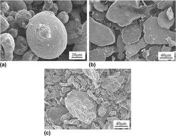
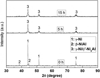
Figure 1 shows the morphology of the un-cryomilled and cryomilled NiCr5AlY powder. The as-received spherical powder [Fig. 1(a)] experienced a transition from flake-shaped [Fig. 1(b)] to polygonal structure [Fig. 1(c)]. The equivalent diameter of the powder increased from 58.43 to 74.39 µm, and then decreased to 34.78 µm. The morphological evolution was attributed to the continuous welding and fracturing of the powder during mechanical cryomilling. Reference Kubaski, Cintho and Capocchi14,Reference Khodsiani, Mansuri and Mirian15 According to the XRD patterns of the un-cryomilled and cryomilled NiCr5AlY powder [Fig. 2], the un-cryomilled powder consisted of γ-Ni (rich in Cr) and β-NiAl. The diffraction peaks of Y2O3 were not detected due to relatively lower content. After increasing the cryomilling time, the diffraction peaks of β-NiAl disappeared, whereas the diffraction peaks of γ-Ni/γ′-Ni3Al were broadened and their intensities were also reduced.
Morphology of NiCr5AlY powder (a) before cryomilling and after cryomilling for (b) 5 h, (c) 15 h.

XRD patterns of NiCr5AlY powder before cryomilling and after cryomilling.

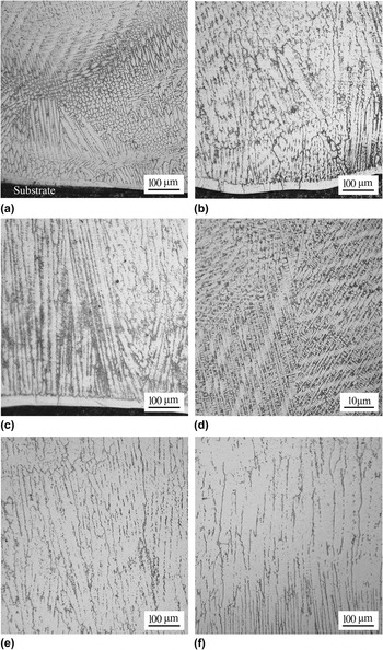
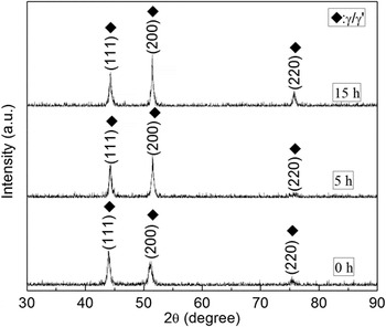
Figure 3 shows the microstructure of the un-cryomilled and cryomilled NiCr5AlY coatings. For the un-cryomilled coating, the un-oriented dendrites were observed near the coating-substrate interface [Fig. 3(a)]. However, when the cryomilling time increased from 5 to 15 h, the fine dendrites [Fig. 3(b)] transformed into the oriented columnar dendrites with the main stems which were parallel to a direction ∼10° to the normal of the coating-substrate interface [Fig. 3(c)]. Vilar et al. Reference Vilar, Santos, Ferreira, Franco and da Silva16 also reported the similar microstructure of NiCrAlY coatings which were deposited on (100) single-crystalline Ni-based superalloy by laser cladding. In the centre of the un-cryomilled coating, many equiaxed dendrites nucleated and grew randomly in different sizes [Fig. 3(d)]. In contrast, the microstructure in the centre of the cryomilled coatings was mainly composed of an array of long, parallel, and oriented columnar dendrites [Figs. 3(e) and 3(f)]. By the XRD observation (Fig. 4), all of the coatings were characterized by γ/γ′ and β-NiAl phase was not detected.
Microstructure at the coating-substrate interface: (a) un-cryomilling and after cryomilling for (b) 5 h and (c) 15 h. Microstructure in the centre of the coating: (d) un-cryomilling and after cryomilling for (e) 5 h and (f) 15 h.

XRD patterns of the un-cryomilled and cryomilled NiCr5AlY coatings by LIHC.

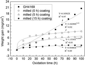
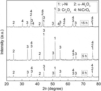
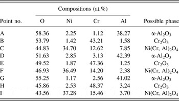
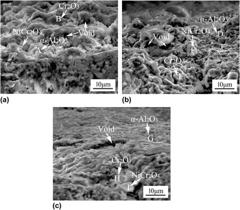
Figure 5 shows the oxidation kinetics for various NiCr5AlY coatings and superalloy GH4169 at 1423 K. The weigh gain of superalloy GH4169 increased linearly as increasing the oxidation time, suggesting that the oxidation kinetics of superalloy GH4169 had a linear law. For the un-cryomilled and cryomilled NiCr5AlY coatings, the weight gains first increased sharply and then presented a slower increase with the prolonged oxidation time, indicating that the oxidation kinetics of un-cryomilled and cryomilled NiCr5AlY coatings had sub-parabolic laws. Nevertheless, increasing the cryomilling time resulted in a decrease in weight gain of the NiCr5AlY coating, indicating that the mechanical cryomilling can improve the oxidation resistance of the NiCr5AlY coating. Combining the XRD results (Fig. 6) with the EDS analysis (Table I), the TGO layer on the un-cryomilled coating was mainly composed of Cr2O3 and NiCr2O4, but contained a relatively smaller amount of α-Al2O3 [Fig. 7(a)]. Increasing the cryomilling time led to an increase in α-Al2O3 in the TGO layer [Fig. 7(b)]. Particularly, when the cryomilling time was increased to 15 h, although the TGO layer contained small amounts of NiCr2O4 and Cr2O3, the fine α-Al2O3 was covered with the surface of the coating [Fig. 7(c)].
Oxidation kinetic curves of the substrate and the various NiCr5AlY coatings by LIHC at 1423 K for 100 h.

XRD patterns of the oxide products formed on the un-cryomilled and cryomilled NiCr5AlY coatings by LIHC.

Chemical composition of the typical zones in the un-cryomilled and cryomilled NiCr5AlY coatings by LIHC.

SEM images showing the typical surface morphologies of the oxide products: (a) un-cryomilled and after cryomilling for (b) 5 h and (c) 15 h.

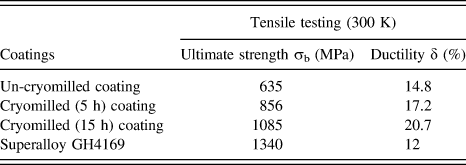
The tensile properties of the un-cryomilled and cryomilled NiCr5AlY coatings by LIHC at room temperature are listed in Table II. For the un-cryomilled NiCr5AlY coating, the ultimate strength and ductility were only 635 MPa and 14.8%, respectively. When the cryomilling time was increased from 5 to 15 h, the ultimate strength (σb) of the coating was increased from 856 to 1085 MPa and the ductility (δ) was increased from 17.2% to 20.7%, respectively. Although the ultimate strength of the cryomilled (15 h) coating was inferior to that of superalloy GH4169 (1340 MPa), the ductility of the cryomilled (15 h) coating was 1.7 times higher than that of superalloy GH4169 (12%). Therefore, this study showed that the cryomilling can also improve the mechanical properties of the NiCr5AlY coatings.
Tensile properties of the un-cryomilled and cryomilled NiCr5AlY coatings by LIHC at room temperature.

IV. DISCUSSION
The evolution of the equivalent diameter for the NiCr5AlY powder was a result of competition between welding and fracturing during mechanical cryomilling. Reference Picas, Forn, Adjelsztajn and Schoenung17 At the initial stage of cryomilling, the spherical particles were flattened due to plastic deformation. Subsequently, the flattened particles experienced a welding process, resulting in the formation of the large flake-shaped particles and the increasing of particle size [Fig. 1(b)]. Clearly, the deformation and welding can overcome the fracturing in this stage. With a continuation of cryomilling, the hardness of powder particles continued to increase due to the extensive plastic deformation. The equiaxed particles were formed, which in turn induced the formation of random welding orientation particles. Reference Alkin and Courtney18 Therefore, the continuous increase in hardness of powder particles and the concurrent decrease in ductility led to an increased tendency of fracturing and a decrease in particle size [Fig. 1(c)]. Obviously, the fracturing can overcome the welding in this stage. Moreover, the severe plastic deformation can induce the dissolution of β-NiAl, resulting in the disappearance of the diffraction peaks corresponding to β-NiAl (Fig. 2). Furthermore, the broadening Bragg peaks implied the nanocrystalline nature of γ/γ′, whose average grain size was estimated using the Scherrer equation. Reference Aoki, Wang, Memezawa and Masumoto19 When the cryomilling time was increased from 5 to 15 h, the calculated grain size was decreased from 32 to 18 nm. This was due to the severe plastic deformation of NiCr5AlY powder during mechanical cryomilling, which in turn led to the increasing of lattice strain and the multiplication of intergranular dislocations. Reference Suryanarayana20 As a result, a cellular structure with the small angle grain boundaries was formed by the sliding and rearrangement of dislocations, and thereby transformed into nano-sized grains in the NiCr5Al powder.
The microstructure of the cryomilled NiCr5AlY coating by LIHC was determined by the ratio of the temperature gradient G to the solidification velocity V. Generally, the solidification velocity V rapidly increased from zero at the bottom of the molten pool to a value close to the laser scanning speed Vs. In contrast, the temperature gradient G was highest at the bottom of the molten pool and decreased as the surface of the molten pool was approached. Reference Gäumann, Bezençon, Canalis and Kurz10 Therefore, the G/V was infinite at the bottom of the molten pool, resulting in the planar growth. With increasing distance from the bottom of the molten pool, the G/V decreased rapidly and therefore led to the columnar dendrites [Fig. 3(a)]. As the solidification proceeded continuously, the actual temperature readily fell below the equilibrium liquidus temperature ahead to the solid–liquid interface due to a dynamic undercooling. This in turn led to the nucleation of the equiaxed dendrites in the un-cryomilled NiCr5AlY coating [Fig. 3(d)].
After the NiCr5AlY powder was cryomilled, not only the defects such as vacancies, dislocations, and twin crystals were induced, but also the polygonal morphologies were generated (Fig. 1). This in turn can produce the multiple reflections in the cryomilled NiCr5AlY powder, whose laser absorption was increased significantly. As a result, the laser energy absorbed by superalloy GH4169 was reduced markedly. The temperature gradient G estimated numerically Reference Rosenthal21 was increased remarkably and the cooling rate expressed as the product of the temperature gradient G and the solidification velocity V was also increased. Thus, the secondary dendrite arm spacing was refined significantly [Figs. 3(b) and 3(c)] and the columnar-to-equiaxed transition was retarded, Reference Zhou, Xiong, Dai, Liu, Zhang and Wang12 inducing the columnar growth in the cryomilled NiCr5AlY coatings [Figs. 3(e) and 3(f)].
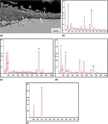
Compared to the un-cryomilled NiCr5AlY coating where many equiaxed dendrites were presented, the solidification morphology in the cryomilled NiCr5AlY coatings was rather columnar. Obviously, the cryomilled coatings had much less grain boundaries, which can provide less diffusion pathways for the transport of O, Al, Cr, and Ni, and eventually can limit the progress of oxidation. Reference Vilar, Santos, Ferreira, Franco and da Silva16 Therefore, increasing the cryomilling time can decrease the weight gain of the NiCr5AlY coating (Fig. 5), and therefore the oxidation resistance of the cryomilled (15 h) coating was approximately nine times higher than that of superalloy GH4169. The morphology of GH4169 superalloy after isothermal oxidation (Fig. 8) indicated that the internal oxidation occurred because it contained a low Al content. According to the EDS analysis, the blocky metal marked A should be GH4169 [Fig. 8(b)] and the top oxide marked B should be NiO [Fig. 8(c)], while the bottom oxides marked C may be the mixed oxides, Al2O3 + Ni(Cr,Al)2O4 due to large amounts of Ni, Al, and O, and small amounts of Cr [Fig. 8(d)]. Moreover, the discontinuous Al2O3 oxide was also formed at the interface of TGO and substrate, as shown in Fig. 8(e). Therefore, the formation of the mixed oxides, NiO and the discontinuous Al2O3 as well as the occurrence of the internal oxidation led to a linear increase in oxidation kinetics of superalloy GH4169 as increasing the oxidation time.
(a) Cross-sectional morphology of GH4169 superalloy after isothermal oxidation at 1423 K for 100 h, (b) EDS result of zone marked A, (c) EDS result of zone marked B, (d) EDS result of zone marked C, and (e) EDS result of zone marked D.

From thermodynamic point of view, Al tends to be oxidized preferentially in the NiCr5AlY coating. With the prolonged oxidation time, the faster growing θ-Al2O3 was transformed into the stable α-Al2O3, suggesting a relatively slower oxidation rate (Fig. 5). Once Al was completely consumed, the Al-depletion zone was formed and subsequently Cr as the second element was oxidized to form Cr2O3. This in turn can guarantee the rapid replenishment of oxide elements to form the protective α-Al2O3 and Cr2O3. Reference Wu, Qin, Feng, Liang, Sun and Wang4 Once Al and Cr elements were consumed in quantity, Ni element can also be oxidized due to its higher chemical concentration, resulting in the formation of thermodynamically unstable NiO. The oxide–oxide reaction was induced readily: NiO + Cr2O3 → NiCr2O4, leading to the generation of spinel NiCr2O4. Moreover, the unequal diffusion rates of Al, Cr, Ni, and O in the TGO layer can also induce the Kirkendall voids. Reference Liu and Gao22 As a result, the voids were formed in the TGO layers which were similarly composed of the mixed oxides such as α-Al2O3, Cr2O3, and NiCr2O4 (Fig. 6). Moreover, the complex stresses consisting of the growth stress and the thermal stress can be developed when these mixed oxides were produced during isothermal oxidation. Reference Zhu, Li, Javed, Liang and Xiao3 The plastic deformation occurred so as to release these stresses in the TGO layer. This in turn can induce the sliding of grain boundaries, resulting in the intergranular voids, and the wrinkling morphologies (Fig. 7). The presence of voids and the accumulation of complex stresses can be the origin of crack initiation, and subsequently cause spalling in the TGO layers. Reference Clarke23 Many methods were put forward to measure the stress at the growth temperature, such as XRD, Raman spectroscopy, and photostimulated optical luminescence. Reference Evans and Lobb24,Reference Kadolkar, Watkins, De Hosson, Kooi and Dahotre25 Nevertheless, the corrections must be made which was very difficult because the thermo–physical properties of alloy and oxides were not accurately known. The previous results indicated that the growth stress and the thermal stress of Cr2O3 formed at 800 °C are ∼23 GPa and ∼1 GPa, respectively, showing that the only decohesion initiated in Cr2O3. Reference Zhang, Zhang, Chellali and Dong26 Alternatively, the growth stress and the thermal stress of NiCr2O4 formed at 1100 °C were ∼63 GPa and ∼2 GPa, respectively, indicating that the thermal stress was compressive. The cracking and spalling were caused by the growth stress and promoted by the thermal stress. Reference Zhang, Zhang, Chellali and Dong26
Moreover, the intergranular voids were formed both in the TGO layer and in the coatings (Fig. 9). The intergranular voids in the TGO layer mainly resulted from three aspects. The first one was that Cr2O3 suffered from the heat damage to form the volatile CrO3 at 1000 °C or beyond of 1000 °C. Reference Zhu, Li, Javed, Liang and Xiao3 The second one was the Kirkendall voids due to the unequal diffusion rates of Al, Cr, Ni, and O in the TGO layer. Reference Evans and Lobb24 The third one was that the plastic deformation of TGO layer caused the generation of intergranular voids by grain boundary sliding to release the growth stress. Reference Clarke23 Similarly, the intergranular voids in NiCr5AlY coatings also resulted from the Kirkendall effect and the grain boundary sliding, which accelerated the spalling of the TGO layers.
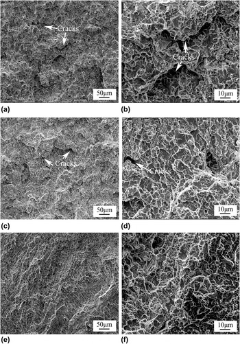
Fracture morphology of the un-cryomilled and cryomilled NiCr5AlY coatings by LIHC. (a) Un-cryomilled (0 h) coating, (b) magnified morphology of (a), (c) cryomilled (5 h) coating, (d) magnified morphology of (c), (e) cryomilled (15 h) coating and (f) magnified morphology of (e).

The mechanical properties of the cryomilled NiCr5AlY coatings increased with the increase in the cryomilling time. This was because the cryomilled coating had fine columnar dendrites compared to the un-cryomilled coating and the former had much less grain boundaries than the latter, which in turn can decrease the probability of crack initiation. According to the fracture morphologies of the NiCr5AlY coatings shown in Fig. 9, all of the tensile samples exhibited the mixed brittle–ductile fracture which was characterized by quasicleavage steps and dimples. Large amounts of equiaxed dendrites with different orientations [Figs. 3(a) and 3(d)] were distributed inhomogeneously in the un-cryomilled coating. This in turn led to a relatively worse compatible capability between the grain deformations, and therefore induced the crack initiation to accelerate the fracturing [Figs. 9(a) and 9(d)]. However, the fine columnar dendrites were induced in the cryomilled NiCr5AlY coating due to increasing the cooling rate and the temperature gradient. The relatively smaller dimples which were approximately parallel to the columnar dendrites were formed [Figs. 9(e) and 9(f)]. These fine columnar dendrites were endowed with a good combination of the enhanced strength and the improved ductility due to the compatible deformation capability. Reference Hall27
V. CONCLUSIONS
The as-received spherical NiCr5AlY powder experienced a transition from flake-shaped to polygonal structure with the increase in the cryomilling time. The equivalent diameter of the NiCr5AlY powder first increased, and then decreased. The un-cryomilled and cryomilled NiCr5AlY coatings by LIHC were composed of γ-Ni/γ′-Ni3Al. Although the un-cryomilled and cryomilled NiCr5AlY coatings were similarly composed of the mixed oxides such as α-Al2O3, Cr2O3, and NiCr2O4, increasing the cryomilling time led to an increase in α-Al2O3 in the TGO layer. As a result, the oxidation resistance of NiCr5AlY coatings at 1423 K was improved. It was noted that, when the cryomilling time was increased further to 15 h, the oxidation resistance of NiCr5AlY coating at 1423 K was approximately nine times than that of superalloy GH4169. Moreover, the tensile strength of the cryomilled (15 h) coating increased to 1085 MPa and the ductility was 1.7 times higher than that of superalloy GH4169 (12%).
ACKNOWLEDGMENTS
This work was financially supported by the National Natural Science Foundation of China (Grant No. 51261027 and 61475117), Tianjin Municipal Science and Technology Commission of China (Grant No. 13ZCZDGX01109), the Aviation Science Foundation of China (Grant No. 2014ZE56013) and the Natural Science Foundation of Jiangxi Province (Grant No. 20132BAB206012).