I. INTRODUCTION
Boron nitride nanotube (BNNT) and carbon nanotube (CNT) composites are an exciting class of novel materials because of their very attractive mechanical properties. Pure BNNTs also have superior thermal, chemical, and toxicity characteristics compared with their carbon analogs in addition to having experimentally determined mechanical strengths rivaling those of CNTs.
Composites containing CNTs are well known, but work still continues to fabricate and tailor improved composites of CNTs with polymers and metals.Reference Curtin and Sheldon1, Reference Iqbal, Goyal and Xanthos2 Pure and functionalized CNTs also continue to elicit enormous attention because of their remarkable electronic, optical, and mechanical properties.Reference Van Lier, Van Alsenoy, Van Doren and Geerlings3–Reference Yakobson, Campbell, Brabec and Bernohlc7 Because of their remarkably high mechanical strengths at the nanoscale level,Reference Treacy, Ebbesen and Gibson8–Reference Krishnan, Dujardin, Ebbesen, Yianilos and Treacy11 a tremendous amount of work has been dedicated to investigating structural applications of CNT composites. Metal–CNT composites are extremely interesting because they can replace pure metals in a variety of applications. The most interesting of these metal–CNT composites resulted from mixing catalyst precursors with a metal matrix, and subsequently growing CNTs directly into the matrix.Reference Goyal, Weigand, Owens and Iqbal12, Reference Goyal, Wiegand, Owens and Iqbal13 This process is highly efficient, as it eliminates a number of steps associated with rival processes, ensuring an even distribution of nanotubes throughout the composite and providing strong bonding between the nanotubes and the metal with little damage to the nanotubes or the composite. Nanotube infiltration by this method was shown to increase mechanical strength by 45% relative to control samples of the neat metals at relatively small loadings. This substantial increase is due entirely to the high strength of the CNTs. BNNTs also possess similar strength and some properties that are superior compared with CNTs and have therefore garnered growing interest in recent years.Reference Chopra and Zettl14 They are chemical cousins of CNTs, forming a rolled graphite-like structure composed of alternating nitrogen and boron atoms which gives them properties as remarkable as those of CNTs. For example, they possess mechanical strength similar to that of CNTs and electronic properties that, unlike CNTs, are independent of tube chirality, thus making them more desirable for electronic applications requiring insulating and semiconducting properties.Reference Lee15–Reference Golberg, Bando, Kurashima and Sato18 There are many other important advantages of BNNTs in comparison with their carbon analogs. CNTs burn in oxygen at a relatively low temperature, as opposed to BNNTs that are stable in air up to 1000 °C.Reference Golberg, Bando, Kurashima and Sato18 If isotopically enriched boron is used, BNNTs will form a useful shield against radiation. BNNTs could also perform better under compressive loading than CNTs. BNNTs are nontoxic compared to CNTs, which have been shown in a number of studies to be cytotoxic.Reference Chen, Wu, Rousseas, Okawa, Gartner, Zettl and Bertozzi19, Reference Lam, McCluskey and Hunter20 Composites made from BNNTs could thus be used more safely for biological applications than CNTs. A process to fabricate BNNT–metal composites is therefore highly desirable because of these unique properties of the BNNTs.
One of the best approaches to metal–nanotube composites is that used by Goyal et al.,Reference Goyal, Weigand, Owens and Iqbal12, Reference Goyal, Wiegand, Owens and Iqbal13 which creates a strong composite by evenly distributing CNTs throughout the bulk of the metal matrix and using them to firmly anchor the metal particles in the composite. This prevents the movement of the metal particles, strengthening the composite material. Here a related chemical vapor deposition (CVD) process is described that can be used to grow BNNTs into a metal matrix to form a high strength metal–nanotube composite. The process involves the use of iron boride (Fe2B) which has been previously demonstrated to catalyze the synthesis of BNNTs.Reference Fu, Lu, Xu, Huo, Wang, Li, Hu and Chen21 Iron (Fe) is a well-known catalyst for ammonia decomposition and it facilitates the growth of BNNTs at a lower temperature. Nitrogen from the decomposition of ammonia reacts to form the BNNTs, which grow out from the Fe particle. The Fe particles therefore provide an ideal matrix for the formation of the Fe –nanotube composite. As nanotubes grow from different Fe particles, they can eventually grow into a neighboring Fe particle to form bridges across metal particles to increase the mechanical strength of the composite material.
As discussed below, the Fe2B catalyst is pressed into a pellet and then exposed to ammonia to form a composite structure comprising micron-sized Fe fused together by BNNTs. An ideally nanostructured BNNT–Fe composite, the first of its kind to the best of our knowledge, is thus formed. BNNTs have been used to improve the mechanical properties of materials such as glass, providing an increase in strength of 90% and an increase in fracture toughness up to 35%, using only a 4 wt% loading of BNNTs.Reference Choi, Bansal and Garg27 BNNTs, however, have never been mixed with a metal to form a composite and also never been directly grown into a matrix to deliberately improve the mechanical properties of the composite formed.
II. EXPERIMENTAL
The Fe2B catalyst was made using a solution process that is described in references.Reference Fu, Lu, Xu, Huo, Wang, Li, Hu and Chen21–Reference Jiang, D’ezsi, Gonser and Lin24 Briefly, 0.1 mol dm−3 aqueous FeSO4 (500 mL) was added dropwise to 1 mol dm−3 aqueous KBH4 (500 mL) over 30 min with strong agitation at room temperature. The powder product of Fe–B was dried in argon after being washed in turn with distilled water, ethanol, and acetone. A slow rate of addition and performing much of the process in an inert atmosphere is critical to prevent excessive oxidation. The reaction is relatively straightforward and scalable. As the process is performed in an aqueous medium, significant oxidation of the catalyst occurs. According to ultra violet–visible (UV–vis) spectroscopy and energy dispersive x-ray (EDX) analyses the Fe2B catalyst is roughly 59–65% Fe, 4–5% boron, and the rest is oxygen with a slight potassium impurity by mass. The large amount of oxide present is reduced by the hydrogen produced by the decomposition of ammonia during the CVD reaction. The control of the Fe2B catalyst particle size is critical for optimal growth of the BNNTs. Approximately 30 min of dropwise addition of FeSO4 solution to KBH4 solution is needed to produce Fe2B of optimal particle size to function as a catalyst.
Different mixtures of pure Fe powder and Fe2B catalyst were then created together and pressed into pellets. Roughly, 3 g of total material was used for each pellet and the pellets had the following amounts by weight of Fe2B catalyst: 0% (control), 0.1%, 1%, 10%, 50%, and 100%. The mixtures were ground using a mortar and pestle in acetone to form a very fine, free flowing powder. The pellets were then pressed using a 13-mm KBr pellet die set with loads of 9000 kg. The density of the pellets in comparison to the density of pure Fe (7.87 g/cc) was 72–74% for the 0%, 1%, and 10% catalyst-loaded pellets. The 50% catalyst-loaded pellet had a density of 60% of pure Fe and the 100% catalyst-loaded pellet had a density of 50% of pure Fe.
In an attempt to increase the density of the Fe2B catalyst pellets, catalyst particles were heat-treated with hydrogen at temperatures of 500 and 1000 °C, and with carbon monoxide at a temperature of 1000 °C. Also, the 100% catalyst-loaded pellets were pressed using cold isostatic press compression at 207 and 1380 MPa in an attempt to further increase the density.
An induction heater from Ameritherm Inc. (Scottsville, NY) was used as the heating source, with a quartz tube reactor as the reaction vessel. The heated container used was a graphite crucible where the various samples were placed. The reactor was flushed with argon (at a flow rate of 160 sccm, standard cubic centimeters per min) for 30 min, and then the pellet was slowly heated to 1100 °C over the course of 30 min under flowing argon. Afterwards, the argon flow was switched to nitrogen flowing at ∼160 sccm and ammonia at 8 sccm. The reaction was stopped after 3 h and the material was allowed to cool for 2 h in an argon atmosphere. The catalyst loadings of the samples used were as mentioned above. Some samples containing 100% catalyst were gas-treated, and some samples were reacted for 10 min with an ammonia flow rate of 32 sccm for faster reaction. Long CVD reaction times were found to deform the pellets; therefore, shorter reaction times were preferably used.
III. RESULTS AND DISCUSSION
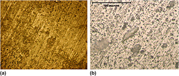
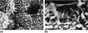
The samples with catalyst loading ≥50% exhibited a high degree of porosity after pressing. Gas treatment and CIP of the pellet did not seem to alleviate the problem. The pellets that reacted slowly exhibited inhomogeneities, possibly as a result of damage to the metal matrix and growth of amorphous boron nitride. However, the pellet that had 100% catalyst and was reacted rapidly appeared to be fairly homogeneous and only showed slight deformation, possibly from uneven heating during synthesis. This indicates that a fast reaction would be ideal for a scaled-up industrial process. Figures 1(a) and 1(b) show optical microscopic images of a pellet composed of only the Fe2B catalyst before and after the CVD reaction. The most striking feature is the high porosity of the starting green pellet and the reacted pellet indicating that porosity is introduced during pellet preparation and does not change after the CVD reaction.
Optical images at 500x of a pellet (a) before chemical vapor deposition (CVD) reaction, and (b) after CVD reaction.

To confirm the presence of boron nitride, Raman, fourier transform infrared spectroscopy (FTIR) and EDX measurements were performed. Raman spectroscopy revealed a line near 1370 cm−1 indicating the presence of boron nitride. The dominant feature of the Raman spectra is a peak at 1366 cm−1, which corresponds to the E2g mode of h-BN in agreement with earlier work.Reference Arenal, Ferrari, Reich, Wirtz, Mevellec, Lefrant, Rubio and Loiseau25 FTIR spectroscopy showing lines peaking at 1384 cm−1 and 804 cm−1 also indicated the presence of boron nitride.Reference Gan, Ding, Huang, Huang, Cheng, Tang and Qi26 As a final confirmation, EDX analyses were performed on the samples prepared. Boron was too light to be detected by EDX; however, nitrogen, Fe and traces of potassium impurity were found.
The x-ray diffraction (XRD) pattern from the composite revealed the presence of Fe, Fe2B, and iron nitride (Fe3N)indicating that the reaction with ammonia transforms Fe2B into pure Fe while growing the BNNTs. The oxide formed on the catalyst particle is completely reduced because Fe oxides are not observed in the XRD pattern from the composite. The XRD line intensities from the BNNTs are most likely too weak in comparison with those from the Fe -containing components to be observed.
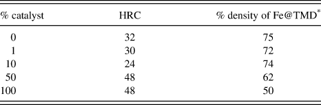
A Rockwell hardness testing set-up was used to determine the hardness of the samples. Before CVD treatment all of the samples were very soft, almost like a plastic and possessing similar hardness. After the CVD treatment, all of the samples became much harder. In the case of pure Fe, one would expect that sintering and nitride formation would be responsible for the increase in hardness. However, for the samples prepared with catalyst, the deposition of BNNTs would also contribute to the increase in hardness. Although boron nitride is a soft material, BNNTs are mechanically very strong in the axial direction so that their in situ formation would lead to enhancement in mechanical properties, such as hardness. Because of the high oxygen impurity content and difficulty in pressing the precursor nanopowders, high density pellets were difficult to prepare with higher catalyst loadings. The pellets with low catalyst loading were actually softer than the control pellets. This is most likely because Fe mixed with the catalyst covered the catalyst particles when pressed, precluding the occurrence of a CVD reaction. Moreover, the catalyst lowered the density of the pure material, ultimately resulting in a softer material.
The pellet loaded with 100% catalyst is much harder than the control pellet. Attempts to cut open the pellets loaded with 50% and 100% catalyst were extremely difficult. They each destroyed a diamond saw blade, providing evidence that the inside of the pellets is harder than the measured surface hardness. The pellet with 50% catalyst came out severely deformed, probably because of the mismatch during the reaction between the catalyst and pure Fe. This made the material made using 100% catalyst more attractive for further investigation. However, although the pellets made with 100% catalyst were very hard, each with a HRC level of 48, the pellet that was reacted rapidly was the least deformed. Remarkably, although far harder than the control pellet, the pellet originally composed of the pure catalyst material was far less dense and more porous. The results of the hardness tests are shown in Table I. One should note that according to the American Society of Mechanical Engineers standards, porous pellets should not be used for hardness testing, although in the present case it is probably acceptable as the hardness results were found to be highly reproducible (see, American Society for Testing and Materials, ASTM E18-05-e1).
Hardness of pellets with varying amounts of catalyst.

* Theoretical maximum density (TMD).
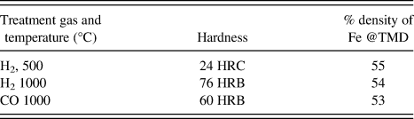
Attempts to improve the density of the material were unsuccessful. As there was significant oxide on the catalyst, hydrogen and carbon monoxide treatment was thought to be an effective reduction method to eliminate the oxygen. By first reducing the oxide on the catalyst particles, then pressing the pellet, and finally running the CVD reaction one would expect to obtain a higher density pellet. Unfortunately, the gas treatment also eliminated the higher hardness after the CVD reaction. The hydrogen-treated pellet at 500 °C is far softer than the control sample, and gas treatments at 1000 °C provided pellets that are even softer. The samples treated at 1000 °C were so soft that accurate hardness measurements could only be made in the Rockwell Hardness B Scale (HRB), depth of penetration into sample by 1/16-inch-diameter (1.588 mm) steel sphere. This is probably because the catalyst before treatment is thermally very sensitive, and thus is easily damaged even by moderate heat treatment. CIP at both pressures also did not improve the density significantly, so further experimentation was not conducted on the pellets pressed in this manner. Table II shows the results of the hardness measurements on pellets of the gas-treated catalyst particles.
Hardness of gas-treated pellets.

Knoop microhardness measurements were performed and converted into HRC values because the Knoop method avoids the larger pores in the material and determines the hardness without the much larger pores, although avoiding the pores altogether is not possible. At the smaller scale, the HRC value was found to be 65.
Measurement of the elastic modulus was performed using the nonintrusive ultrasound method by use of Eq. (1) below:

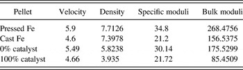
where C is the bulk modulus and p is the density. The pellet with no catalyst was compared with the pellet that was reacted rapidly and had 100% catalyst. Despite superior hardness, the catalyst-treated pellet possessed a much lower modulus of elasticity and specific elasticity than the control pellet. Most likely, this difference comes from the high porosity of the 100% catalyst-loaded pellet. This is very interesting and implies that the material is highly resistant to thermal shock. The results of the ultrasound measurements and calculations of the bulk moduli are shown in Table III.
Ultrasound measurements from 0% catalyst to 100% catalyst pellets.

The density is in g/cc, the velocity is in mm/μm, the bulk moduli are in GPa, and the specific moduli are in kN m/kg units.
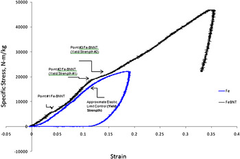
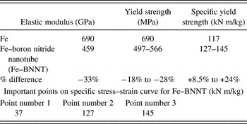
The control pellet and the pellet reacted rapidly with 100% catalyst were compared using stress–strain measurements. Compressive specific stress–strain curves at strain rates of 0.025/s and at ambient conditions were obtained as shown in Fig. 2. Table IV shows the results derived from this data. The two major differences between the samples are the porosity and the addition of BNNTs, which are in competition with each other. Specific values are used to normalize the effect of porosity to some degree, and in the case of the hardness tests, the higher porosity was more than the cancelled out by the addition of BNNTs.
Specific stress–strain curves of iron–boron nitride nanotube (Fe–BNNT) composite (black) and pure Fe (blue).

Mechanical properties obtained from the stress–strain curve.

The stress–strain curves corrobated evidence from the hardness and ultrasound measurements indicating that the Fe–BNNT composite exhibited mechanical properties that were distinct from that of the Fe control sample. The yield strength was difficult to determine exactly for the experimental sample because of its complicated behavior, but it was assumed to range from point number 2 to point number 3 in Fig. 2. The Fe–BNNT composite possessed a yield strength of 18–28% lower than that of the control sample. This is most likely because of the porosity in the Fe–BNNT control sample. Additionally, the elastic modulus of the control sample was 31% higher than that of the experimental sample. This indicates that the Fe–BNNT composite possesses lower stiffness and strength than the pure Fe sample. This behavior was also partly observed in the ultrasound measurements, where the bulk modulus of the control sample was 51% greater than that of the experimental sample. When comparing mechanical properties, one should recall that the experimental sample was also much lighter than the control because of its porosity, hence, a specific stress–strain curve is reported here. This curve shows that the experimental sample has a specific yield strength that is 8.5–24% greater than that of the control sample.
The control sample showed excellent mechanical properties compared with that of regular pure Fe. One would expect under the treatment conditions nitridization would occur. It is of sufficient temperature and ammonia exposure. The experimental sample exhibits rather interesting properties as well. This abnormal behavior has been observed before in a ceramic composite system.Reference Sen, Schofield, O’Dell, Deka and Pillay28 From Fig. 2 it is evident that the Fe–BNNT sample rarely exhibits nonlinear stress–strain behavior; however, instead there are regions where the linear behavior changes nonlinearly because of the complex properties of the material. The regions where these changes occur are indicated in Table IV. Up until point 1 in Fig. 2, the experimental data is linear but experiences a sudden nonlinearity followed by a return to its original linear behavior. Most likely, large pores dictate the behavior of the material as in Ref. Reference Sen, Schofield, O’Dell, Deka and Pillay28 and a speculative explanation would be required to account for this. Up until point 1, the largest pores are strained heavily, until the pellet is densified suddenly, followed by large pores dictating the behavior of the material until point 2, where the material is densified again. Finally, at point 3, although there are still large pores present, the biggest pores have been eliminated, and the material once again exhibits linear behavior until it fails because of the growth of cracks. Failure of the BNNTs is unlikely because of their expected remarkable strength, therefore, most likely Fe–Fe or BNNT–Fe connections represent the failure points. However, despite porosity and initial flaws essentially dictating the mechanical properties of the composite sample, its specific strength and hardness are far higher than that of the control specimen. This suggests that if a process to eliminate porosity was found, the BNNT–Fe composites would have much higher values of strength than those measured here.
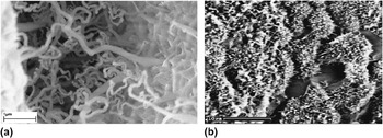
Scanning electron microscope (SEM) images taken from the BNNT–Fe composites are shown in Figs. 3–5. The SEM image in Fig. 3(a) shows the BNNTs grown on the surface of a pellet with 100% catalyst. The BNNTs in the image can be seen forming interparticle bridges in bundles with diameters ranging from 20 to 100 nm. Figure 3(b) is an image of the fractured inside surface of a composite pellet showing the nanoscale adhesion of the BNNTs to the Fe particles as a result of the in situ process used here to synthesize the composite.
Scanning electron microscope (SEM) images of: (a) the surface of a BNNT–Fe composite pellet and (b) interior of a cracked BNNT–Fe composite pellet.

An obvious feature of the inside of the pellet is its high porosity. One cause of this is the large change in density when the Fe oxide is reduced by hydrogen after the reaction of ammonia with boron. This leaves pores throughout the inside of the material, thus weakening it. If the pores could be eliminated, the composite would become significantly stronger and tougher. The inside of the pellet is covered with BNNTs which are directly connected to Fe particles suggesting that the BNNTs bond well with the Fe particles.
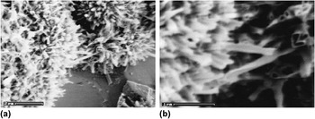
Bridging of BNNTs across the Fe particles is evident from the SEM images in Figs. 4 and 5. In particular, a bundle of nanotubes is seen joining two separate particles while under tension and necking in Fig. 5. This is an excellent example of structural reinforcement, and provides evidence that the BNNTs can neck and undergo substantial elongation before breaking, unlike bulk ceramics. In this regard, one should note that the distribution of BNNTs was more uniform in the interior than on the surface of the pellets.
SEM images of: (a) interior of a cracked BNNT–Fe pellet showing BNNTs bridging from particle to particle, and (b) a closer view of two particles joined by.

SEM images showing: (a) overview of BNNT–Fe composite with multitude of BNNTs and (b) closer view of two Fe particles bridged by a stretched BNNT bundle in the composite.

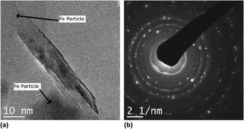
Transmission electron microscopy (TEM) and selected area electron diffraction were used to provide a more detailed characterization of the BNNT–Fe composites. Figure 6(a) is a TEM image showing ∼5-nm diameter, ten-walled BNNT bridging two Fe particles in the BNNT–Fe composite. The nanotube dimensions from the image are in essential agreement with that of previous work.Reference Fu, Lu, Xu, Huo, Wang, Li, Hu and Chen21
(a) Transmission electron microscope image of a multiwall BNNT with 10 walls joining two Fe particles in the BNNT–Fe composite; and (b) selected area electron diffraction taken from the BNNT–Fe composite. The spacings and assignments of the different phases in the composite are given in Table V.

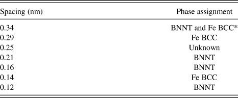
The electron diffraction pattern [Fig. 6(b) with calculated spacings from the reflections shown in Table 5] provides evidence for the presence of BNNTs, Fe BCC, and an unknown phase with one line which did not correspond to any of the expected phases.Reference Smith, Jordan, Park, Kim, Lillehei, Crooks and Harrison29, Reference Zhong, Overney and Tomanek30 The unknown spacing of 0.25 nm can be tentatively assigned to a weakly bonded Fe–BNNT phase that might have formed during synthesis. No evidence for Fe2B and Fe3N was found in the selected area of the electron diffraction pattern, although these phases were detected in the XRD patterns that cover a much larger area of the sample.
Spacings observed from electron diffraction pattern and phase assignments.

* Body centered cubic (BCC).
IV. CONCLUSIONS
The in situ growth of BNNTs directly into an Fe matrix discussed in this article provides a BNNT–metal nanocomposite with a number of benefits. If the nanotubes were grown first and added to the metal powder, they would have to be grown separately from the catalyst, mixed intimately with an Fe matrix (an extremely difficult process), and then pressed without damaging the nanotubes—a process that would also be difficult. The process described here removes a number of steps by directly growing the nanotubes in one-step in the pellet. Because the boron nitride nanotubes can be grown using an Fe2B catalyst, the Fe from the catalyst forms the matrix, thereby providing a novel and facile route to a metal–BNNT composite with high yield strength.
The electron-microscope images indicate that the composite formed is an ideally nanostructured material with nanoscale basic constituents that are distributed in an interconnected network. Its mechanical properties can be improved by further compression using an isostatic press. Additionally, the BNNTs provide a thermally and chemically stable barrier protecting the Fe matrix, making the material extremely strong and resistant to chemical and thermal attack in harsh environments. Moreover, as BNNTs are biologically noncytotoxic according to the most recent studies, the Fe–BNNT composite would be ideal for use in medical applications.
ACKNOWLEDGMENTS
RBP thank the following collaborators: Victor Greenhut for assistance with the SEM imaging of the fracture surface, Paul Anderson for general guidance in setting up the laboratory equipment and use of his laboratory space, Peggy Sanchez for performing the FTIR measurements, Mike Hespos for performing the hardness measurements, Sean Swaszek for measuring the stress–strain curves, Steve Miller and Wojtek Tutak for help in obtaining the TEM images, Steve Bottglieri for Knoop hardness measurements and Ed Hochberg for UV–Vis analysis. RBP also thank Wes Cobb at Denver University for assistance in making ultrasound measurements and Bill Davis for image processing help. JL and ZI thank Armament Research Development and Engineering Center (ARDEC), Picatinny for financial support.