Introduction
Recently, due to the massive use of wireless devices, rapid growth in the field of wireless communication has been observed. Ultra wideband (UWB) plays a very important role in wireless communication. UWB systems are based on impulse radio, in which the communication is based on very short duration baseband pulses [Reference Win and Scholtz1]. UWB refers to a signal or a system having a relatively large bandwidth which is approximately greater than 500 MHz. Federal Communications Commission (FCC) in 2002, permitted the use of unlicensed bandwidth ranging from 3.1 GHz to 10.6 GHz for commercial implementation of UWB technology [2]. Acquiring a large bandwidth emerges the need of transmitting data at a high data rate and the best solution for the achievement of this kind of transmission is the use of UWB technology. For a large amount of data transmission, data can be digitally transmitted over a large bandwidth using short radio pulses with low power for short-range [Reference Fontana3]. An approach to maximize the transmitted power is represented using the synthesis of fields. The proposed technique is effective to provide high beam efficiency [Reference Morabito, Lagana and Isernia4]. In UWB systems, transmission, as well as the reception of information, is carried out using carrier-free, short duration (ps-ns) pulses employing a low duty cycle so that the transmission of low power signals over a large bandwidth can be done. For achieving this large bandwidth some researchers have used uneven patch shapes such as tapered patch and hexagonal patch [Reference Khan, Rahman, Khan and Saleem5, Reference Singh and Pujara6]. Many researchers have been using elliptical and circular patch shapes [Reference Ghanbari, Keshtkar, Ghanbari and Jarchi7–Reference Ghosh, Ghosh, Ghosh and Chattopadhyay10].
This tremendous increasing bandwidth in UWB systems generally causes interference to other pre-defined bands in the system named as wireless local area network (WLAN, 2.4–2.484 GHz, 5.15–5.35 GHz, and 5.725–5.825 GHz), world interoperability for microwave access (WiMAX, 2.5–2.69 GHz, 3.4–3.69 GHz, and 5.25–5.825 GHz), satellite digital multimedia broadcasting (S-DMB, 2.63–2.655 GHz) [Reference Dong, Hong, Kuai, Yu, Zhang and Chen11]. To reduce interference with these predefined bands the solutions could be either designing a source pulse with zero power spectral density for predefined bands or design a UWB antenna with notched band characteristics, which does not radiate at these above-mentioned bands. The best technique for the introduction of notch characteristics is the insertion of slots and slits in the patch [Reference Zhang, Jiao, Yang and Hong12, Reference Sharma, Vyas and Yadav13]. Few designs on UWB with notch characteristics proposed by other researchers include complementary split-ring resonator (CSRR), slots on the ground or patch area, and split ring resonator (SRR) out of which CSRR is very commonly used [Reference Siddiqui, Saha and Antar14–Reference Peng, Wang, Zhao and Liu18]. Another research presents a proximity fed design indulging a circular radiating patch placed inside the rectangular-shaped slot concentric with respect to the center. The patch area is etched by an open ring slot and the feed area is etched by a π-shaped slot for achieving the dual-band notch for 3.5 and 5.5 GHz respectively [Reference Ali, Saad and Khaled19].
In [Reference Zhang, Hong, Yu, Kuai, Don and Zhou20] a CPW-fed circular patch with a pair of split-ring slots and two arc-shaped slots has been proposed. The two split ring slots are responsible for the two different notched bands 2.4 and 3.5 GHz, and two arc-shaped slots provide the notch band for 5.8 GHz. Another design with a CPW-fed elliptical patch is presented [Reference Rashmi and Singh21]. In this, two incomplete C-shaped symmetrical slots have been engraved on the ground plane for introducing the band notch for 5.5 GHz band. A pair of Minkowski fractals has also been etched symmetrically on the patch area for 5.8 GHz band. Another design presents a Ψ-shaped antenna with notch characteristics for two bands in which, ω-shaped slot is etched to achieve notch characteristic for WiMAX band and inverted C-shaped slot for WLAN band [Reference Pandey, Singh, Bharti and Meshram22]. In [Reference Liu, Yin, Liu, Wang and Xu23], a CPW-fed design exhibiting band notch for the dual band has been proposed. In this, a hexagonal shaped patch with circular slotted ground is presented. For obtaining the band-notch characteristics, pair of two L-shaped branches are added symmetrically to the circular slot of the ground plane [Reference Liu, Yin, Liu, Wang and Xu23]. A dual band-notched antenna with two slits and a circular ground plane is proposed in [Reference Bong, Hussain, Rhee, Gil and Kim24]. This antenna consists of a radiator patch with two slits out of which one is V-shaped and the other is split ring-shaped. An asymmetrical structure consisting of a rectangular patch and two inverted L-shaped slots on the square ground plane has been proposed in [Reference Dastranj and Bahmanzadeh25]. This design successfully achieves the whole UWB bandwidth.
In [Reference Sanyal, Sarkar and Chowdhury26], an octagonal shaped monopole antenna has been proposed in which the size of the antenna is halved designed by disturbing the geometry of the radiator and the ground [Reference Sanyal, Sarkar and Chowdhury26]. Further, an antenna with a spline curve as a radiating part has been proposed in which PSO for time-domain analysis is also presented in [Reference Lizzi, Oliveri and Massa27]. In [Reference Liu and Xu28] M-EBG (modified electromagnetic-band gap) structure consisting of two strip patches has been designed further, a band rejection is achieved by placing the strip patch near the feed line.
A CPW fed antenna comprising of hybrid shaped patch and rectangular slotted ground with a pair of stubs placed symmetrically has been proposed in [Reference Dastranj and Arand29]. A strip-line fed rectangular patch with two circular-edged and a ground with rectangular slot has been presented in [Reference Al-Halawani, Al-Najjar and Abdelazeez30]. Miniaturization to achieve multi-band operation in UWB antenna is proposed in [Reference Ali, Mohammad Saadh, Birdar, Ujar and Anguera31]. In this, the slots in the radiator as well as in the ground have been etched to operate at multiband. In [Reference Rahman, Jahromi, Mirjavadi and Hamouda32] a CPW fed antenna with slots in the radiator as well as in the ground are inserted to achieve multiband notches. A modified maple leaf-shaped UWB antenna comprising triple notch bands has been proposed in [Reference Iqbal, Smida, Mallat, Islam and Kim33]. In this article, all the three bands in the proposed design can be independently controlled. An antenna with SRR is proposed in [Reference Parihar and Sharma34]. In this, a circular patch with SRR and elliptical split ring resonator pair (ESRRP) near the feed line is proposed. It can also be inferred from [Reference Abdelraheem and Abdalla35] that the half-circular or half elliptical patches are more compact as compared to any other shape. Many researchers are frequently working on the UWB antennas which can be applicable to the biomedical field for tumor detection. A UWB antenna with a biomedical application is discussed in [Reference Ahmed, Hasan and Chowdhury36].
In this paper; the proposed methodology presented in [Reference Zhang, Hong, Yu, Kuai, Don and Zhou20] has been extended to achieve the desired results. This paper is arranged in such a manner that section II gives a detailed overview of the antenna design and implementation including its evolution followed by section III, which provides an explanation and discussion about results. Section IV comprises of conclusion, in which the paper is summarized.
Proposed design and implementation
Figure 1 shows the front and rear view of the proposed antenna design which consists of the radiating patch, substrate, and ground plane. The substrate is covered with a partial ground plane on one side and radiating patch on the other. The radiating element consists of a split symmetric elliptical patch with a multi-section feed line. The feed line consists of three sections with different lengths and widths. This acts as a multi-section impedance transformer that efficiently matches to the source impedance of 50 ohms at the feed point over a wide frequency range.
Structure of designed UWB antenna (a) Front View (b) Rear View.

The dimensions for the parameters used for designing the proposed antenna are given in Table 1.
Parameters with dimensions (unit: mm).

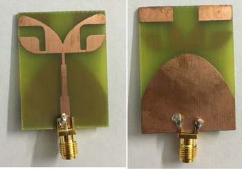
The proposed design is fabricated on FR4 substrate having ɛr = 4.4 and thickness = 1.6 mm andtan (δ) = 0.0024. The ground and patch both are comprised of a perfect electric conductor (PEC) having a thickness of 0.035 mm. The final structure of the proposed UWB antenna is depicted in Figs 1(a) and 1(b) respectively.
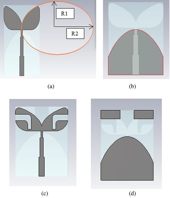
The first step to design is the formation of an ellipse as shown in Fig. 2(a). Then the ¾ part of the ellipse is chamfered to achieve the quarter ellipse. The remaining part of the ellipse is then blended from the corners. This blended shape is responsible for the smooth behavior of the overall band. Figure 2(b) shows the proposed ground plane of the design. This plane is tapered with user-defined spline coordinates [Reference Liu, Yin, Liu, Wang and Xu23]. The optimized coordinates are generated from the parametric analysis done in time-domain simulation. The upside-down L-shaped slot has been introduced in the patch to catalyze notch characteristics as shown in Fig. 2(c). This slot has been etched till the end to make it an infinite length slot. Two identical stripes are added to the upper-end corners of the ground plane to increase the sharpness of the notch as shown in Fig. 2(d).
Evolution of the proposed UWB notched antenna.

Prototype of proposed antenna in rear and top view.

Results and discussions
The suggested antenna is designed and simulated in Computer Simulation Technology Microwave Studio (CST MWS) which is a 3D electromagnetic simulation software that can be commercially used and is based on finite integration technique (FIT). The design parameters have been optimized using parametric study. The optimized design has been fabricated with the help of a wet-etching facility based on the photolithography method. A suitable SMA connector is then connected to the feed line of the fabricated antenna. To measure reflection co-efficient, Agilent E507IC vector network analyzer (VNA) is available in Antenna Research Laboratory situated in Department of Electronics and Communication Engineering, T.I.E.T., Patiala. For radiation pattern measurement, Anechoic Chamber is used which is available at Millimeter/THz Wave Laboratory, Department of Electronics and Communication Engineering, I.I.T., Roorkee.
Reflection Co-efficient
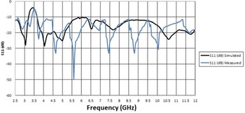
The reflection coefficient is used to evaluate the antenna based on matching characteristics. The value of the reflection coefficient suitable for good antenna performance is −10 dB. Figure 4 portrays the collation between the simulated and measured reflection coefficient of the proposed UWB antenna.
Reflection Coefficient with Notch characteristics for the proposed antenna.

The reflection coefficient of the proposed UWB antenna satisfies −10 dB criteria from 2.5–12 GHz, providing the bandwidth of almost 9–10 GHz which includes the whole UWB band. Further, the proposed UWB antenna shows a notch characteristic at 3.5 GHz.
Radiation pattern and gain
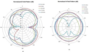
The E-plane and H-plane radiation patterns for the presented antenna exhibiting notched band characteristics are shown in Figs 5(a) and 5(b) respectively. The shape of a radiation pattern of E-plane is typically dumbbell-shaped while that of H-plane is omnidirectional.
Measured radiation patterns of proposed antenna with notch.

The gain of the proposed UWB notch antenna is shown in Fig. 6. As inferred from this figure, the maximum gain is 2.58 dBi. The dip of −0.404 dBi of gain in the plot indicates the corresponding notch frequency of 3.5 GHz.
Gain of the band-notch antenna.

Gain.

Group delay
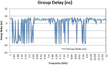
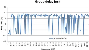
The antenna system measurement gives actual results in the real world without an anechoic chamber. So, two identical antennas were placed in two different situations one in a face-to-face orientation and the other in side-by-side orientation separated by a distance of 30.0 cm. Figures 7 and 8 show S21-parameter for both the orientations. The group delay variation for the overall band is almost constant except for the notch frequencies. For notch frequencies, the group delay shows the peaks corresponding to the higher value of S21- parameter.
Group Delay (Face to Face Orientation).

Group Delay (Side by Side Orientation).

Current distribution
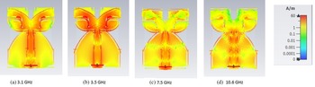
Figure 9 shows the current distribution of the suggested antenna at various frequencies viz. 3.1, 3.5, 7.5 and 10.6 GHz. Figures 9(a), 9(c) and 9(d) show the current distribution for frequencies lying before and after the notch band. The current distribution at the notch frequency i.e. 3.5 GHz is shown in Fig. 9(b) which demonstrates that the inverted L-shaped slot is mainly responsible to exhibit notch characteristics.
Current Distribution at (a) 3.1 GHz (b) 3.5 GHz (c) 7.5 GHz and (d) 10.6 GHz.

Radiation efficiency
Figure 10 shows the radiation efficiency of the proposed antenna. It can be observed from the graph that the efficiency of the proposed antenna varies from 60% to 90%. The minimum efficiency reported is 62% at 3.5 GHz which is the notch frequency of the proposed antenna.
Radiation Efficiency.

Table 3 shows the comparison of the proposed antenna with previously published designs in terms of size, bandwidth, and notched-band of the antenna.
Comparison of the proposed antenna with previous antennas.

Conclusion
In this article, the UWB antenna exhibiting notch characteristics at 3.5 GHz has been suggested. The proposed design has successfully achieved UWB bandwidth. The slot length in the patch is so chosen that makes it an infinite length slot providing the shape of the wings of a butterfly. The radiation pattern of the suggested design is fairly dumbbell-shaped in E-plane and omnidirectional in H-plane and the gain is lesser than 5 dBi with the group delay less than 10 ns for the whole UWB range. The design is fabricated on a cost-effective FR4 substrate. The far-field measurements of the fabricated antenna show good matching with respect to the simulated ones.
Acknowledgements
The authors would like to thank the Department of Electronics and Communication Engineering at T.I.E.T, Patiala, and I.I.T., Roorkee for facilitating VNA setup and radiation pattern measurements respectively.
 Neha Ahuja received her B. Tech degree in ECE from Punjab Technical University, Jalandhar. She received her Master's degree in ECE from Thapar Institute of Engineering and Technology, Patiala in 2012. Currently, she is pursuing her Ph.D. degree from Thapar Institute of Engineering and Technology, Patiala. Her main research interests include millimeter wave technology, ultra-wideband antenna, Band notched antenna and DRA.
 Rajesh Khanna received a B.Sc. (Engg.) degree in ECE in 1988 from REC, Kurukshetra and M.E. degree in 1998 from IISc., Bangalore. He was with Hartron R&D center till 1993. Until 1999, he was in AIR as Assistant Station Engineer. Presently, he is working as Professor in the ECED at Thapar Institute of Engineering and Technology, Patiala. He has published 176 papers in national and international journals/conferences. He has worth Rs 1.8 crore projects to his credit. His main research interest includes antennas, wireless communication, MIMO systems.
 Jaswinder Kaur received her BTech and MTech degrees in ECE from Punjab Technical University, Jalandhar, in 2005 and 2009, respectively. She received her Ph.D. degree from Thapar University in 2014. Presently, she is working as an Assistant Professor in ECED at Thapar Institute of Engineering and Technology, Patiala. She has published 48 papers in various peer-reviewed journals/conferences of national and international repute. Her research interests include the analysis and design of microstrip antennas for wireless communication, implantable antennas for biomedical applications, 5 G MIMO antennas, CSRR loaded antennas, microwave integrated circuits (MICs), and microwave & RF design.