1. Introduction
In the past years, precision agriculture (PA) has become a prominent research field, thanks to its significant impact for responsible water resource consumption [Reference Kumar and Ilango1], but also fertilisers, chemicals and pesticides reduction [Reference Bongiovanni and Lowenberg-Deboer2, Reference Meshram, Vanalkar, Kalambe and Badar3]. The increasing population growth rate, which is expected to bring the global population to 9.7 billion by 2050 [4], is leading to a raise in food demand [Reference Pierce, Nowak and Sparks5–Reference Griffin and Yeager7], especially in developing countries where land was withdrawn from cultivation for cities expansion [Reference Oliver, Bishop and Marchant8], with a greater exploitation of the fields and mass crops. PA methods are nevertheless devoted to a data-driven approach for responsible and intelligent crops farming, thus pursuing the 2030 Agenda for Sustainable Development, especially the sustainable development goal (SDG) 12 towards sustainable consumption and production patterns [9].
To this aim, a massive scientific activity about the implementation of novel technologies for crops farming was performed in the past decades, especially about integrated mobile systems that are capable of autonomous navigation while monitoring the crops [Reference Rosas, de Carvalho Pinto, de Queiroz, de Melo Villar, Valente and Martins10–Reference Chawade, van Ham, Blomquist, Bagge, Alexandersson and Ortiz12], or even capable of helping farmers during their activities, e.g. trimming [Reference Strisciuglio, Tylecek, Petkov, Bieber, Hemming, Henten, Sattler, Pollefeys, Gevers, Brox and Fisher13–Reference Botterill, Paulin, Green, Williams, Lin, Saxton, Mills, Chen and Corbett-Davies15], spraying [Reference Adamides, Katsanos, Constantinou, Christou, Xenos, Hadzilacos and Edan16, Reference Goričanec, Kapetanovič, Vatavuk, Hrabar, Vasiljevič, Gledec, Stuhne, Bogdan, Orsag, Petrovič, Miškovič, Kovačič, Kurtela, Bolotin, Kožul, Glavič, Antolovič, Anič, Kozina and Cukon17] and harvesting [Reference Feng, Wang, Wang and Li18, Reference De Preter, Anthonis and De Baerdemaeker19]. All the cited systems are briefly presented in Table I and their main features, e.g. the main purpose and manipulator type, are reported.
Mobile manipulators for precision agriculture.

To develop a novel UGV (unmanned ground vehicle) for PA purposes, the researchers from Politecnico di Torino had developed the Agri.Q prototype, depicted in Fig. 1, which is a custom mobile manipulator mainly designed for grapevine cultivation [Reference Cavallone, Botta, Carbonari, Visconte, Quaglia, Niola and Gasparetto20, Reference Botta, Cavallone, Quaglia, Gasparetto, Petuya and Carbone21].
The Agri.Q mobile manipulator for Precision Agriculture.

Agri.Q locomotion system is composed of two modules: the front and rear modules, both equipped with two drive motors and four wheels. While the significant number of wheels is fundamental to properly distribute the UGV weight on the ground, the all-wheels drive mode is fundamental to navigate in case of steep slopes or uneven terrains. The system is also provided with a photovoltaic panel, which allows the self-charging mode, and it can be properly oriented, thanks to a controlled pitch-roll motion, to exploit the solar radiation, thus maximising the self-charging mode. Moreover, the integration with the Kinova Jaco2 commercial robotic arm makes the system capable of performing few tasks where the interaction with the environment is fundamental, e.g. crop sampling and spraying.
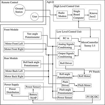
In Fig. 2, the Agri.Q High-Level architecture is presented. The electric energy is stored into a 7S14P Li-Po battery that can be both re-charged by an external supply or the PV panels themselves. The rover can be directly commanded by a human being user through a remote control, whose receiver gives the input commands to the low-level micro-controller that drives the mobile base motors. Alternatively, the mobile base can operate in autonomous mode through the commands provided by an on-board computer, which can also control the robotic manipulator.
High-Level architecture of the Agri.Q mobile manipulator.

Apart from the novelty of the Agri.Q prototype, which was already discussed by the authors within the previously cited works, this article presents the motion planning pipeline that was developed to allow Agri.Q to perform simple crop sampling activities, exploiting both the mobile base and the arm mobility. Significant contributions of the paper are specified hereinafter:
-
The implementation of a closed-form inverse kinematics algorithm that exploits the elbow redundancy for the Jaco2 manipulator is extensively presented and developed, and it is also provided by the authors as an open-source code for further research activities;
-
The whole system motion planning pipeline is reported, presenting also how the decoupling of the base mobility and arm mobility can be used to place the target object of the pick-and-place task inside the area where the arm exhibits its highest manipulation capacities.
The present work is the extended version of the paper presented by the authors at the 31st International Conference on Robotics in the Alpe-Adria-Danube Region [Reference Colucci, Baglieri, Botta, Cavallone and Quaglia22]. The following chapters are organised as follows:
2. Jaco2 Manipulator Inverse Kinematics
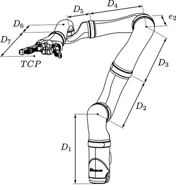
The Kinova Jaco2 robotic manipulator can be modelled as a serial kinematic chain composed of eight links and seven revolute joints, where the first link is fixed to the Agri.Q rover and the last one represents the end-effector. In Fig. 3, the Jaco2 manipulator and its geometric properties is presented. It is worth underlining the elbow off-set
 $e_2$
inducing a misalignment in the kinematic chain that will be discussed further. Since the arm should operate in a three-dimensional workspace with an arbitrarily defined orientation, its seven degrees of freedom guarantee the kinematically redundancy of the system [Reference Baillieul, Hollerbach and Brockett23]; thus, for each pose, there are
 $\infty ^1$
possible solutions to the inverse kinematics problem. The definition of the link frames was performed through the use of the Denavit–Hartenberg convention, even though the coefficient values were slightly modified to make them consistent when commanding the real manipulator, as can be verified by comparing the values in Table II with the parameters in the official documentation [24].
Kinova Jaco2 Manipulator and its fundamental geometric properties. The elbow off-set is labelled as
 $e_2$
.

Denavit–Hartenberg parameter values for the Jaco2 Manipulator for each ith reference frame.

According to the official Kinova documentation, the fixed homogeneous transformation matrix that sets
 $\{0\}$
with respect to
 $\{b\}$
is the following:
 \begin{equation} \mathbf{T}^{b}_{0} = \begin{bmatrix} 1 & \quad 0 & \quad 0 & \quad 0 \\[5pt] 0 & \quad -1 & \quad 0 & \quad 0 \\[5pt] 0 & \quad 0 & \quad -1 & \quad 0 \\[5pt] 0 & \quad 0 & \quad 0 & \quad 1 \end{bmatrix} \end{equation}
The position and orientation of the frame fixed to the
 $i$
th link can be easily found with the composition rule of homogeneous transformation matrices:
 \begin{equation} \mathbf{T}^{b}_i (q_{1},\ldots,q_{i}) = \begin{bmatrix} \mathbf{R}^{i-1}_{i} & \mathbf{p}^{i-1}_{i} \\[7pt] \mathbf{0} & 1 \end{bmatrix} = \begin{bmatrix}{r^{i-1}_{i}}_{11} & \quad &{r^{i-1}_{i}}_{12} & \quad &{r^{i-1}_{i}}_{13} & \quad &{p^{i-1}_{i}}_{x} \\[7pt] {r^{i-1}_{i}}_{21} & \quad &{r^{i-1}_{i}}_{22} & \quad &{r^{i-1}_{i}}_{23} & \quad &{p^{i-1}_{i}}_{y} \\[7pt] {r^{i-1}_{i}}_{31} & \quad &{r^{i-1}_{i}}_{32} & \quad &{r^{i-1}_{i}}_{33} & \quad &{p^{i-1}_{i}}_{z} \\[7pt] 0 & \quad & 0 & \quad & 0 & \quad & 1 \end{bmatrix} = \mathbf{T}^{b}_{0} \; \mathbf{T}^{0}_1(q_{1}) \; \ldots \; \mathbf{T}^{i-1}_{i} (q_{i}) \end{equation}
where
 $q_{i}$
is the
 $i$
th generalised coordinate and
 $T^{i-1}_{i}$
is the so-called homogeneous transformation matrix of frame
 $i$
with respect to frame
 $\{i-1\}$
that can be computed as a function of the DH parameter and
 $q_{i}$
:
 \begin{equation} \mathbf{T}^{i-1}_{i} = \left [{\begin{array}{c@{\quad}c@{\quad}c@{\quad}c} \cos (q_{i}) & -\cos (\alpha _{i})\sin (q_{i}) & \sin(\alpha _{i})\sin (q_{i}) & a_{i}\cos (q_{i}) \\[5pt] \sin (q_{i}) & \cos (\alpha _{i})\cos (q_{i}) & -\sin (\alpha _{i})\cos (q_{i}) & a_{i}\sin (q_{i}) \\[5pt] 0 & \sin (\alpha _{i}) & \cos (\alpha _{i}) & d_{i} \\[5pt] 0 & 0 & 0 & 1 \end{array} } \right ] \end{equation}
where, in the following, the compact notation
 $s_{i} = \sin (q_{i})$
and
 $c_{i} = \cos (q_{i})$
is also used.
2.1. Swivel Angle Approach
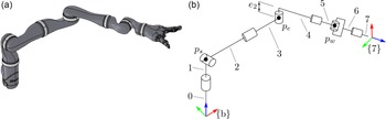
To face the inverse kinematics problem and compute the posture (or, in general, the postures) that is consistent with a specified end-effector pose, the serial kinematic chain that forms the manipulator can be represented as the composition of two spherical joints linked by a revolute joint. Indeed, as shown in Fig. 4, the axes of the first three joints intersect at a single point named
 $p_s$
, where
 $s$
stands for “shoulder,” and the axes of the last three joints meet in
 $p_w$
, since the manipulator wrist is spherical. In analogy with the human arm, the central joint represents therefore the elbow mobility, and the kinematic (or intrinsic) redundancy of the manipulator can be addressed by evaluating the elbow centre point
 $p_e$
when
 $p_s$
and
 $p_w$
are fixed, leading to the so-called elbow angle or swivel angle approach. Since the spherical wrist joint is accountable for the end-effector frame
 $\{7\}$
orientation, its position is instead ruled by the first four revolute joints that allow the rotation of the elbow point
 $p_e$
along a circle
 $S$
of radius
 $R$
(Fig. 5).
Modelling of the Kinova Jaco2 Manipulator as a composition of two spherical joints with an intermediate revolute joint. (a) 3D manipulator model, (b) Kinematic model.

Rotation of the elbow point
 $p_e$
along the swivel circle
 $S$
of radius
 $R$
.

Representation of the characteristic parameters of the elbow angle IK approach.

It is worth noticing that the swivel circle
 $S$
can be seen as the intersection of two cones that have
 $p_e$
and
 $p_w$
as their respective vertices, while the apothems depend on the geometric parameters
 $D_{1},D_{2},D_{3},D_{4}$
and
 $e_2$
. In detail, while the apothem
 $L$
of the cone with vertex in
 $p_S$
is
 $U = D_{1}+D_{2}$
, the geometric off-set
 $e_2$
causes a misalignment in the serial kinematic chain, thus the apothem of the second cone does not coincide with the sum
 $D_{3}+D_{4}$
. By observing Fig. 6, it is quite straightforward that, by defining:
 \begin{equation} L = D_{3}+D_{4} \end{equation}
the apothem of the cone with
 $p_w$
as vertex can be computed as
 \begin{equation} L_{\perp } = \sqrt{L^2 + e_{2}^2} \end{equation}
Thus, to make use of the elbow angle approach, the position of the wrist centre
 $p_w$
can be derived as follows:
 \begin{equation} \mathbf{p}_{w} = \mathbf{p}^{b}_{7} - (D_{6}+D_{7}) \ \left[{r^{b}_{7}}_{13} \quad {r^{b}_{7}}_{23} \quad {r^{b}_{7}}_{33}\right] \end{equation}
where
 $\mathbf{p}^{b}_{7}$
is the given goal position of the end-effector frame with respect to
 $\{b\}$
and
 $\left[{r^{b}_{7}}_{13} \quad {r^{b}_{7}}_{23} \quad {r^{b}_{7}}_{33}\right]$
is the third unit vector of the reference frame. To compute the
 $\{\hat{\mathbf{u}}, \hat{\mathbf{v}}, \hat{\mathbf{n}}\}$
triplet, the following approach can be used:
 \begin{equation} \hat{\mathbf{n}} = \frac{\mathbf{p}_{w} - \mathbf{p}_{s}}{|\mathbf{p}_{w} - \mathbf{p}_{s}|} \end{equation}
 \begin{equation} \hat{\mathbf{u}} = \frac{ \hat{\mathbf{u}} - (\hat{\mathbf{u}} \cdot \hat{\mathbf{n}}) \; \hat{\mathbf{n}}}{| \hat{\mathbf{u}} - (\hat{\mathbf{u}} \cdot \hat{\mathbf{n}}) \; \hat{\mathbf{n}}|} \end{equation}
 \begin{equation} \hat{\mathbf{v}} ={\hat{\mathbf{n}}} \wedge{\hat{\mathbf{u}}} \end{equation}
where
 $\hat{\mathbf{a}}$
is an arbitrarily defined unit vector and the underlined notation defines the position vector with respect to the
 $\{b\}$
frame. It is worth underlining that
 $\hat{\mathbf{n}}$
is by definition perpendicular to the swivel circle
 $S$
. The
 $\gamma$
angle, i.e. the semi-vertical angle of the cone with
 $p_s$
as the vertex, can be computed using the law of cosines with the two triangles
 $p_{s}, p_{c} p_{e}$
and
 $p_{c}, p_{e}$
and
 $p_{w}$
:
 \begin{equation} \gamma = \cos ^{-1} \bigg (\frac{U^2 + | \mathbf{p}_{w} - \mathbf{p}_{s}|^2 - L_{\perp }^2}{2 \; | \mathbf{p}_{w} - \mathbf{p}_{s}| \; U}\bigg ) \end{equation}
The position vector
 $\mathbf{p}_c$
of the swivel circle centre and its radius
 $R$
can be easily computed:
 \begin{equation} \mathbf{p}_{c} = \mathbf{p}_{s} + U \;\cos (\gamma )\;\hat{\mathbf{n}} \end{equation}
 \begin{equation} R = U \;\sin (\gamma ) \end{equation}
The position vector of the elbow point
 $\mathbf{p}_{e}$
can now be defined as a function of the derived parameters and the swivel angle
 $\phi$
, i.e. the angle formed between
 $\hat{\mathbf{u}}$
and
 $\mathbf{p}_{e} - \mathbf{p}_{c}$
, and thus it represents the intrinsic kinematic redundancy of the manipulator:
 \begin{equation} \mathbf{p}_{e} = \mathbf{p}_{c} + R \; (\cos (\phi )\;\hat{\mathbf{u}} + \sin (\phi )\;\hat{\mathbf{v}}) \end{equation}
2.2. Joint Angles Computation
Once the position vector
 $\underline{p_{e}}$
has been computed as function of the swivel angle parameter
 $\phi$
, its value can be used to compute the first two joint angles
 $q_1$
and
 $q_2$
. Indeed, by referring to the homogeneous transformation matrix
 $\mathbf{T}^{b}_{3}$
that describes the position and orientation of the reference frame
 $\{3\}$
with respect to
 $\{b\}$
, the following applies:
 \begin{equation} \mathbf{T}^{b}_{3} = \,\mathbf{T}^{b}_{0} \, \mathbf{T}^{0}_1\,\mathbf{T}^{1}_2\,\mathbf{T}^{2}_3 = \begin{bmatrix} s_1\,s_3+c_1\,c_2\,c_3 \quad & \quad c_1\,s_2 \quad & \quad c_3\,s_1-c_1\,c_2\,s_3 \quad & \quad c_1\,s_2\, (D_{2}+D_{3})\quad \\[5pt] c_1\,s_3 - c_2\,c_3\,s_1 \quad & \quad - s_1\,s_2 \quad & \quad c_1\,c_3+c_2\,s_1\,s_3 \quad & \quad - s_1\,s_2\,(D_{2}+D_{3})\quad \\[5pt] c_3\,s_2 \quad & \quad - c_2 \quad & \quad - s_2\,s_3 \quad & \quad D_{1} - c_2\,(D_{2}+D_{3})\\[5pt] 0 \quad & \quad 0 \quad & \quad 0 \quad & \quad 1 \quad \end{bmatrix} \end{equation}
Since
 $\mathbf{p}_{e} = \mathbf{p}^{b}_{3}$
, it is possible to compute the first two joint angles as follows:
 \begin{equation} q_{1} = - \tan ^{-1} \bigg ( \frac{{p^{b}_{3}}_y}{{p^{b}_{3}}_x} \bigg ) \end{equation}
 \begin{equation} q_{2} = \tan ^{-1} \left ({\frac{\sqrt{{p^{b}_{3}}_x \, ^2 +{p^{b}_{3}}_y \, ^2}}{D_{1}-{p^{b}_{3}}_z} } \right ) \end{equation}
The third joint value
 $q_3$
can be calculated by imposing the following identity:
 \begin{equation} \mathbf{p}_{e} - e_{2} \; \left[{r^{b}_{3}}_{13} \quad {r^{b}_{3}}_{23} \quad {r^{b}_{3}}_{33} \right] = \mathbf{p}_{w} + L \; \left[{r^{b}_{4}}_{13} \quad {r^{b}_{4}}_{23} \quad {r^{b}_{4}}_{33} \right] \end{equation}
where
 $[{r^{b}_{3}}_{13} \quad {r^{b}_{3}}_{23} \quad {r^{b}_{3}}_{33} ]$
and
 $\left[{r^{b}_{4}}_{13} \quad {r^{b}_{4}}_{23} \quad {r^{b}_{4}}_{33} \right]$
are the third components of the reference frames
 $\{3\}$
and
 $\{4\}$
that can be extracted from their respective homogeneous transformation matrices:
 \begin{equation} \left[{r^{b}_{3}}_{13} \quad {r^{b}_{3}}_{23} \quad {r^{b}_{3}}_{33} \right] = \left[\begin{array}{c@{\quad}c@{\quad}c} c_3\,s_1-c_1\,c_2\,s_3, & c_1\,c_3+c_2\,s_1\,s_3 , & -s_{2}s_{3} \end{array} \right] \end{equation}
 \begin{equation} \left[{r^{b}_{4}}_{13} \quad {r^{b}_{4}}_{23} \quad {r^{b}_{4}}_{33} \right] = \begin{bmatrix} -s_4 (c_1 c_2 c_3 + s_1 s_3 ) + c_4 (c_1 s_2 ) \\[5pt] -s_4 (s_1 c_2 c_3 + c_1 s_3 ) + c_4 (-s_1 s_2 ) \\[5pt] -s_4 s_2 c_3 - c_4 c_2 \end{bmatrix} \end{equation}
(a) Computation of the elbow angle
 $q_4$
through geometric construction. (b) The wrist centre point
 $p_w$
is projected onto the
 $S_1$
plane.

Even though Eq. (17) is function of
 $q_3$
but also
 $q_4$
, it can still be solved since
 $q_4$
, i.e. the elbow angle, can be directly computed through geometric construction. As presented in Fig. 7(a), the
 $p_w$
point can be translated with a fixed off-set
 $e_2$
along the
 $e_2$
direction, thus obtaining the point
 $p_{w'}$
. Looking at the
 $\{p_s, p_e, p^{\prime}_w \}$
triangle on the
 $S_1$
plane, Fig. 7(b), the value of the elbow joint
 $q_4$
can be easily obtained through the cosine law:
 \begin{equation} q_4 = \ \cos ^{-1} \left ({\frac{L^2 + U^2 - d_{\perp }^2}{2\,U\,L}}\right ) \end{equation}
where
 \begin{equation} d_{\perp } = \sqrt{|\mathbf{p}_{w} - \mathbf{p}_{s} |^2 + e_2 \, ^2} \end{equation}
 $q_3$
can now be computed as
 \begin{equation} \begin{aligned} c_3 = & - \frac{e_2 \, s_2 \,{p_w}_{x} - e_2 \, s_2 \,{p_e}_{x} + c_1 \, c_2 \, e_2 \,{p_e}_{z} - c_1 \, c_2 \, e_2 \,{p_w}_{z} }{s_2 \, (s_1 \, L^2 s_{4}^2 + s_1 \, e_{2}^2)} \\ \\ & \frac{ + L \, s_1 \, s_4 \,{p_e}_{z} - L \, s_1 \, s_4 \,{p_w}_{z} + L \, c_1 \, c_2^{2} \, c_4 \, e_2 + L \, c_1 \, c_4 \, e_2 \, s_2^{2} + L^2 \, c_2 \, c_4 \, s_1 \, s_4}{s_2 \, \left(s_1 \, L^2 \, s_{4}^2 + s_1 \, e_{2}^2\right)} \end{aligned} \end{equation}
 \begin{equation} \begin{aligned} s_3 = & \frac{e_2 \, s_1 \,{p_w}_{z} - e_2 \, s_1 \,{p_e}_{z} - L \, s_2 \, s_4 \,{p_e}_{x} + L \, s_2 \, s_4 \,{p_w}_{x} + L^2 \, c_1 \, c_{2}^2 \, c_4 \, s_4 }{s_2 \, \left(s_1 \, L^2 \, s_{4}^2 + s_1 \, e_{2}^2\right)} \\ \\ & \frac{+ L^2 \, c_1 \, c_4 \, s_{2}^2 \, s_4 - L \, c_2 \, c_4 \, e_2 \, s_1 + L \, c_1 \, c_2 \, s_4 \,{p_e}_{z} - L \, c_1 \, c_2 \, s_4 \,{p_w}_{z}}{s_2 \, (s_1 \, L^2 \, s_4^2 + \, s_1 \, e_2^2)} \end{aligned} \end{equation}
 \begin{equation} q_3 = \tan ^{-1} \left ({\frac{s_3}{c_3}}\right ) \end{equation}
Regarding the values of the last three joint angles, the standard inverse kinematics procedure for spherical joint was applied, thus by evaluating the
 $T^{4}_7$
homogeneous transformation matrix:
 \begin{equation} \mathbf{T}^4_{7} = \mathbf{T}^{4}_b \; \mathbf{T}^{b}_7 \end{equation}
where
 \begin{equation} \mathbf{T}^4_{b} = \begin{bmatrix}{\mathbf{R}^b_{4}}^T \quad & -{\mathbf{R}^b_{4}}^T \; \mathbf{p}^b_{4} \\[7pt] [0,0,0] \quad & 1 \end{bmatrix} \end{equation}
Finally,
 $q_{5}$
,
 $q_{6}$
,
 $q_{7}$
can be computed:
 \begin{equation} q_5 = \tan ^{-1} \left ({ \frac{{r^{4\,}_{7}}_{23}}{{r^{4\,}_{7}}_{13}}} \right ) \end{equation}
 \begin{equation} q_7 = \tan ^{-1} \left ({ \frac{{-r^{4\,}_{7}}_{32}}{-{r^{4\,}_{7}}_{31}} } \right ) \end{equation}
 \begin{equation} q_6 = \tan ^{-1} \left ({ \frac{{r^{4\,}_{7}}_{32}}{\sin (q_{7})} } \right ) \end{equation}
2.3. Redundancy Evaluation
Since the swivel angle approach is a closed-form solution of the inverse kinematics problem for the Jaco2 manipulator, it can be used to extract the entire range of possible postures that corresponds to a given goal pose
 $\mathbf{T}^{b}_{7}$
. Indeed, it is worth noticing the manipulator joint space has size
 $m = 7$
while its workspace has size
 $n = 6$
, thus the arm has
 $m - n = 1$
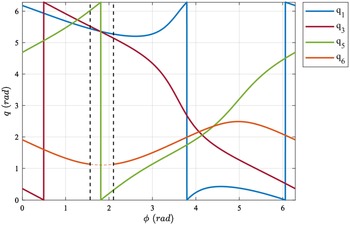
degree of kinematic redundancy. Typically, this feature is exploited to augment the mobility of the manipulator, e.g. for collision avoidance algorithms. The typical behaviour of the joint angle values as a function of the swivel angle
 $\phi$
is presented in Fig. 8, where the curves are presented in the range
 $[0, 2\pi ]$
. Focusing on joint 6 curve, the whole set of possible solutions is restricted due to the physical joint limit constraints that impose a minimum admitted value on
 $q_6$
. In general, the Kinova Jaco2 manipulator presents physical joint limits in joint 2, 4, 6, as presented in Table III. Thus, it seems evident that the closed-form solution can also be exploited to avoid those solutions that are outside or even close to the admitted joint values boundary. To this aim, Vahrenkamp et al. [Reference Vahrenkamp, Asfour, Metta, Sandini and Dillmann25] presented a novel approach in which an extended manipulability index, which takes into account closeness to joint limits and possible obstacles, is presented.
Physical joint limit values for Kinova Jaco2 manipulator.

Behaviour of the values of the joint angles in the interval
 $[0, 2\pi ]$
as a function of the swivel angle
 $\phi$
for a given pose. The black vertical dotted lines demarcate the not allowed solutions due to joint 6 limit constraints.

Starting from Togai’s definition of manipulability index [Reference Togai26], that estimates the posture closeness to kinematic singularities:
 \begin{equation} c(\mathbf{J}) = \frac{1}{\text{cond}(\mathbf{J})} = \frac{\lambda _{\min}}{\lambda _{\max}} \end{equation}
where
 $\mathbf{J} = \mathbf{J}(q_{1},\ldots,q_{7})$
is the arm Jacobian matrix and
 $\lambda _{\min, \max}$
are its minimum and maximum eigenvalues, in refs. [Reference Vahrenkamp, Asfour, Metta, Sandini and Dillmann25, Reference Chen, Selvaggio and Caldwell27] the following penalisation function
 $p_j$
for the
 $j$
th column of the Jacobian is presented:
 \begin{equation} p_j = \frac{1}{\sqrt{1 + |\nabla h(q_{j})_j|}}. \end{equation}
 \begin{equation} \nabla h(q_{j})_j = \frac{\left(\theta _{j,\max} - \theta _{j,\min}\right)^2\left(2\theta _j - \theta _{j,\max} - \theta _{j,\min}\right)^2}{\xi \left(\theta _{j,\max} - \theta _j\right)^2\left(\theta _j - \theta _{j, \min}\right)^2} \end{equation}
where
 $q_{j,\max}$
,
 $q_{j,\min}$
were presented in Table III and
 $\xi$
is an arbitrarily defined parameter that accentuates or relaxes the
 $p_j$
function. In detail, it is easy to check that larger values of
 $\xi$
increase the area where
 $p_j$
has a value close to one. In this paper, the value of
 $\xi =4$
, as used in ref. [Reference Vahrenkamp, Asfour, Metta, Sandini and Dillmann25], was selected.
The manipulability
 $c$
can then be modified into
 $c_{\text{mod}}$
evaluating the condition number of the modified Jacobian, where the
 $j$
th column of the matrix is multiplied with the corresponding penalisation factor
 $p_j$
:
 \begin{equation} J_{\text{mod}_{i,j}} = J_{i,j} p_j \qquad i = 1,\ldots 6 \;, \; j=1,\ldots,7 \end{equation}
The behaviour of
 $c$
and
 $c_{\text{mod}}$
is presented in Fig. 9, where the closeness to the joint 6 physical limit leads to a significant penalisation of
 $c$
.The implementation of the manipulability index
 $c_{\text{mod}}$
therefore establishes a criterion to evaluate the “best” posture that corresponds to a defined goal pose, thus allowing to extract a solution from the inverse kinematics set presented in Fig. 8.
Manipulability index as a function of the elbow angle for a defined goal pose. Vertical dashed lines denote the area not allowed due to joint limit constraints.

3. System Implementation
To properly navigate and collect crops, the manipulator mobility can be augmented thanks to Agri.Q kinematics, i.e. the mobile base mobility, thus making the whole system a mobile manipulator. Even though the Agri.Q mobility is quite complex, due to the articulated architecture and the potential eight drive wheels, as presented by the authors in refs. [Reference Colucci, Botta, Tagliavini, Cavallone, Baglieri and Quaglia28, Reference Carbonari, Botta, Cavallone, Tagliavini and Quaglia29], its kinematics is here simplified for crop collecting purposes that can be classified as pick-and-place tasks.
When navigating inside vineyard rows, the two degrees of freedom that can be used to augment the manipulator mobility are the linear displacement
 $x$
and the pitch angle
 $\psi$
, as presented in Fig. 10. While is quite straightforward is the impact of
 $x$
, it is worth underlining the pitch angle has the double effect of moving the arm upwards but also rotate it.
Agri.Q base mobility simplification for crop sampling.

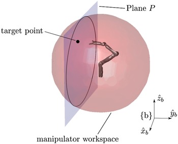
Even though several motion planning algorithms extend the Jacobian of the arm with the base one, thus moving towards the simultaneous motion of the base and the arm [Reference De Luca, Oriolo and Giordano30, Reference Neri, Scoccia, Carbonari, Palmieri, Callegari, Tagliavini, Colucci, Quaglia, Niola, Gasparetto, Quaglia and Carbone31], the motion planning is here addressed with the decoupling of the mobile base motion and the manipulator one, due to the significant difference between the position accuracy of the two systems. According to this approach, the linear displacement
 $x$
and the pitch angle
 $\psi$
are used to position the manipulator near the goal grape peduncle, then the arm is used to perform the pick and place task. Since the base mobility cannot affect the displacement of a grape along the
 $y$
axis of
 $\{b\}$
, the base can translate and rotate the arm workspace (Fig. 11) to position the goal point inside the area where the manipulability index
 $c_{\text{mod}}$
has the highest value [Reference Colucci, Botta, Tagliavini, Cavallone, Baglieri and Quaglia28].
Use of the Agri.Q mobility to translate and rotate the arm workspace. Plane
 $P$
is parallel to
 $\lt \hat{x}_{b}, \hat{z}_{b}\gt$
and its displacement along
 $\hat{y}_{b}$
is established by the position of the target point.

It is worth underlining that, although it significantly simplifies the motion planning pipeline, the proposed approach cannot be used for dynamic handling or grasping, since it is mainly based on a static representation of the environment and the Agri.Q itself. It is also assumed that the Agri.Q base can fulfill the arm positioning task with the theorical absence of positioning errors, which is quite impossible to obtain in a real vineyard. This aspect is partially compensated since the target point is positioned inside the area where the Jaco2 manipulator presents the highest value of manipulabilty index. Thus, if the positioning error is restricted, the target point still lies into the best manipulability area. Nonetheless, the evaluation of the cited area depends on the pose of the target object, i.e. its position along the
 $y$
axis of
 $\{b\}$
and its orientation, so it would be outperformed for each target grapevine, with a significant increment in the overall computational time.
3.1. Software Development
Within the present sub-section, a comprehensive description of the developed software architecture for the system control is presented.
Regarding the closed-form inverse kinematics method presented in Section 2, the developed algorithm is hereafter reported in pseudo-code form in Algorithm 1. Since it can be potentially used for different research activities, the IK code is provided as open-source Matlab code by the authors.Footnote 1 The library was developed using the Matlab multidimensional matrices functionality, to optimise the computation time especially in case of redundancy evaluation, where a significant reduction of the computational cost from the average value of 0.65s to 0.15s was obtained.Footnote 2 The code was further optimised with the Matlab .mex code generation functionality, where the average computation time of 0.09 s was achieved.Footnote 3 The code uses the Solveq sub-function that performs the joint angles computation according to Subsection 2.2.
Inverse kinematics elbow angle algorithm

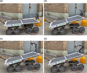
Regarding the Agri.Q system implementation, in Fig. 12 a representation of a first and simplified system software architecture is presented, where the interaction between Matlab and ROS environment was done through the Matlab ROS Toolbox [32]. A camera block will be implemented for object recognition and pose estimation of the target, i.e. the grape peduncle, both before and after the mobile base motion to avoid possible positioning errors of the mobile base, while the manipulator path planning pipeline involves the use of standard sample-based joint space path planning like RRT connect [Reference Kuffner and LaValle33]. Except for the camera block, the presented pipeline was used to perform a first laboratory experimental validation, as shown in Fig. 13. Agri.Q was able to pick-and-place a grapevine sample.
Software system architecture. The Matlab and ROS logo are used to indicate the selected environment for a specific block.

Agri.Q prototype first experimental tests. (a) Rest configuration, (b) goal peduncle approaching, (c) peduncle picking, (d) place of the peduncle.

4. Conclusions
Within this paper, the development and implementation of the motion planning pipeline for Agri.Q mobile manipulator for PA were presented. The algorithm had integrated the resolution of the arm kinematic redundancy through the closed-form elbow angle formulation, that is provided by the author as an open source Matlab code. The whole system motion pipeline was instead addressed using a motion decoupling approach, where the mobile base translates and rotates the manipulator workspace to position the goal point inside the area with the highest value of the manipulability index. The whole architecture was implemented on the real prototype and validated through first tests in laboratory environment. As further developments, a perception block will be developed to both recognise the target peduncle and also provide a feedback after the mobile base motion to correct possible positioning errors.
Acknowledgements
The authors gratefully thank the Pic4Ser - PoliTO Interdepartmental Centre For Service Robotics. https://pic4ser.polito.it/.
Author contributions
GC, AB, LT and GQ conceived and designed the study. GC, LT and AB carried out the software implementation. GQ validated the study. GC and AB prepared the draft of the paper. GQ, LT and LB edited and reviewed the draft.
Financial support
This research received no specific grant from any funding agency, commercial or not-for-profit sectors.
Conflicts of interest
The authors declare no conflicts of interest exist.
Ethical approval
Not applicable.