NOMENCLATURE
- cD
-
drag coefficient of airship
- c xδa , c yδr , c zδe (1/deg)
-
aerodynamic force coefficients of aerodynamic surfaces
- cx , cy , cz
-
aerodynamic force coefficients of airship
- D (m)
-
distance from current position to destination
- ei (i = 1⋅⋅⋅6)
-
weight of maximum thrust of i th propeller
- fi (i = 1⋅⋅⋅6) (N)
-
the thrust magnitude of i th propeller
-
 ${{\bf f}} = {[ {\begin{array}{*{20}{c}} {{f_1}}&{{f_2}}&{{f_3}}&{{f_4}}&{{f_5}}&{{f_6}} \end{array}} ]^{\rm{T}}}$
-
the thrust magnitude vector
- F T
-
vector of thrust and relative moment about the volume centre
- F Tϕ, F Tθ, F Tψ (Nm)
-
attitude moments taken by propellers
- k θz
-
guidance coefficient in altitude control
- k p, kd , ki
-
pID coefficients
- lref (m)
-
reference length of the airship
- m (kg)
-
airship mass
- mx , my , mz
-
aerodynamic moment coefficients about x, y, z axes
- m 11, m 22, m 33 (kg)
-
added masses
- m 44, m 55, m 66, m 26, m 35 (kg·m2)
-
added inertia moments
- m zδr , m yδe , m xδa (1/deg)
-
moment coefficients of aerodynamic surfaces
- M ϕ, M θ, M ψ (Nm)
-
total attitude moment
- M δa, M δe , M δr (Nm)
-
attitude moment taken by aerodynamic surfaces
- M δ
-
transform matrix between control surfaces and synthetic aerodynamic surfaces
- Ix , Iy , Iz , Ixy , Ixz , Iyz (kg·m2)
-
inertia of airship
- p, q, r (rad/s)
-
angular velocities in body-fixed frame
- q ∞
-
dynamic pressure of airflow
- P
-
control coefficient matrix of propellers
- S
-
triangular transform matrix between propellers and thrust magnitude
- Sref (m2)
-
reference area of airship
- T
-
indirect control force vector
- u, v, w (m/s)
-
linear velocities in body-fixed frame
- U A
-
the aerodynamic input vector
- U T
-
the propeller input vector
- U = [UT TUA T]T
-
the control input vector
- Vol (m3)
-
volume of airship
- V(m/s)
-
airspeed of airship
- Vl , Vh (m/s)
-
critical airspeeds in moment allocation
- x, y, z (m)
-
positions of airship
- (xi , yi , zi )(i = 1⋅⋅⋅6) (m)
-
mounting position of i th propeller in body-fixed frame
- w a
-
weight of aerodynamic surfaces in moment allocation
- wp
-
weight of propellers in moment allocation
- wfi (i = 1⋅⋅⋅6)
-
weight of thrust magnitude of i th propeller in actuator allocation
- w μi (i = 1⋅⋅⋅6)
-
weight of vectored angle of i th propeller in actuator allocation
- w δi (i = 1, 2, 3)
-
weight of i th control surface in actuator allocation
- W 1
-
weight matrix of non-stuck propellers
- W 2
-
weight matrix of fault propellers
- W s
-
weight matrix of stuck propellers
- W δ
-
weight matrix of control surfaces
- ϕ, θ, ψ (rad)
-
euler angles
- δ i (i = 1, 2, 3)(o)
-
deflection angle of control surface
- δ a (o)
-
deflection angle of synthetic aileron
- δ e (o)
-
deflection angle of synthetic elevator
- δ r (o)
-
deflection angle of synthetic rudder
- μ i (i = 1⋅⋅⋅6) (rad)
-
vectored angle of it h propeller
- ρ(kg/m3)
-
air density

1.0 INTRODUCTION
An airship has advantages over other aircraft because of large payload ability and hovering ability in the sky, so it has wide application prospect in disaster rescue and earth observation(Reference Takashi, Nakadate and Okuyama1). On the other hand, an airship has large response lag and is susceptible to the environment due to its large volume and low airspeed, so effective control is still the main issue in airship research.
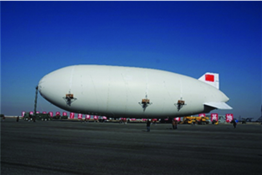
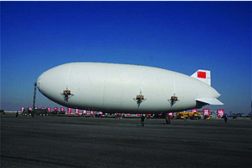
In this article, a mid-altitude unmanned airship flying at altitude of 7000 m is proposed, as shown in Fig. 1; it is 97 m long, with a volume of 28273 m3 and a weight of 34634 kg. For safety reasons, it is equipped with empennages of inverse Y shape and six vectored propellers with three of them located along each side. The maximum thrust of every propeller is 1960 N. Compared with the traditional configuration of two vectored propellers, these multi-vectored propellers share the total thrust together, such that the size of a single propeller is reduced and the agile manoeuvre ability is increased. The multi-vectored propellers can realise vertical take-off and landing, also achieve attitude control at any airspeed; the fault-tolerant ability is improved because of the redundant configuration.
Overall structure of the airship.
Many researchers have conducted studies on the traditional control of an airship(Reference Azinheira, Moutinho and Carvalho2-Reference Zheng, Chen, Xu and Zhu4). Presently, attention is centred on the composite control of stratospheric airships of multi-actuators. Liu et al(Reference Liu, Wu and Hu5) investigated the feasibility and stability of the equilibrium flight of the airship in a longitudinal plane equipped with ballonets and ballast. Fan et al(Reference Fan, Yu and Yan6) studied the altitude control system for a high-altitude airship with an auxiliary ballonet and elevator. Guo and Zhou(Reference Guo and Zhou7) presented a design method of stratospheric airships with aircrew propeller/aerodynamic compound control system. Di et al(Reference Di, Han and Yao8) studied a method for solving the attitude control problem with aerodynamic fin and vectored propeller. Chen et al( Reference Chen, Zhou, Yan and Duan 9 ,) and Chen and Duan(27) analysed the nonlinear composite controller with aerodynamic control surfaces, moving masses and vectored propeller. Some other studies have focused on the composite control of finless airships with vectored thrusters, including finless airships with vectored thrusters(Reference Liesk, Nahon and Boulet10), finless twin-hull airships with vectored thrusters(Reference Battipede, Gili and Lando11), and spherical airships with two vectored thrusters(Reference Rooz and Johnson12). Similar works have also focused on vectored-thrust underwater ships(Reference Berge and Fossen13,Reference Johansen, Fossen and Berge14) .
All of the aforementioned works focused on flight control at the working altitude based on the assumption that all actuators are in normal situation, and there is no failure in the actuators. In this paper, the airship has three aerodynamic surfaces and six vectored propellers offering 15 control degrees of freedom, so the control system is over-actuated. In the case of actuator failures, the remaining ones can be reconfigured by the control allocation without having to change the controller structure.
A control allocation system implements a function that maps the desired control forces generated by the motion controller into the commands of the different actuators. Control allocation problems can be formulated as optimisation problems, where the objective typically is to produce the specified generalised forces while minimising the use of control effort (or power) subject to actuator rate and position constraints, power constraints as well as other operational constraints. The typical methods for control allocation include direct allocation algorithm(Reference Durham15,Reference Bordignon16) , daisy-chaining algorithm(Reference Buffington and Enns17,Reference Enns18) , pseudo-inverse algorithm(Reference Lane and Stengel19,Reference Enns, Bugajski, Hendrick and Stein20) and mathematical programming algorithm(Reference Ikeda and Hood21,Reference Bodson22) . Among these methods, the explicit solutions can be found and implemented efficiently only by using pseudo-inverse algorithm. And the weighted-pseudo-inverse method is further used to construct the reconfigurable system, where the weights are used to represent actuator fault status(Reference Reiman and Dillon23,Reference Davidson, Lallman and Bundick24) .
In this article, the hybrid control allocation scheme of multi-vectored propellers and empennages is given and the composite control system is designed. First, the attitude control moments obtained from the controller are divided into aerodynamic moments and thrust moments, then there is a further allocation of aerodynamic moments among multi-aerodynamic surfaces and allocation of thrust moment and forward thrust among multi-vectored propellers. To reallocate the actuators in case of actuator failure, a weighted pseudo-inverse-based reconfiguration strategy is developed. On the strength of the robustness of the controller, the control law remains unchanged and the weights are varied corresponding to the actuator situation: normal or failed, and thus indicating rapid reconfiguration in case of failures. According to the simulation results under different fault situations, the reconfigurable control system performs more effectively than the normal control system in cases of actuator failures, even given more than one faulty control actuator.
2.0 SYSTEM DYNAMICS
2.1 Dynamic model
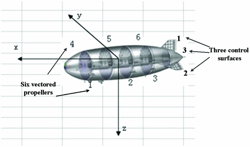
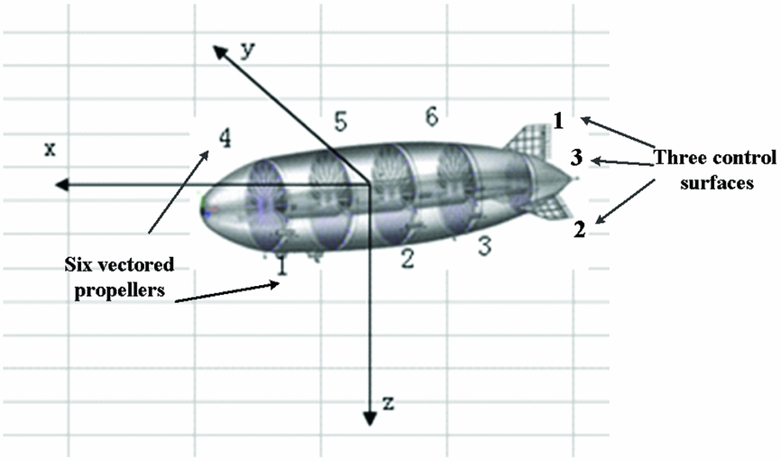
The dynamic model of mid-altitude is established in the body-fixed frame. The body frame is given in Fig. 2, the position of gravity centre in body-frame is (0,0,1.898 m). The dynamics of the mid-altitude airship are similar to that of the conventional airship: external forces and moments are produced by gravity, buoyancy, fluid inertia force, aerodynamics and thrusters. Through the force analysis, the following dynamics equation can be constructed:
Actuator configuration of airship.
 $$\begin{equation}
{{\bf M}}{\left[ {{{\dot{u}}_b}\;{{\dot{v}}_b}\;{{\dot{w}}_b}\;{{\dot{p}}_b}\;{{\dot{q}}_b}\;{{\dot{r}}_b}} \right]^{\rm{T}}} = {{{\bf F}}_{{\bf T}}}{{\bf + }}{{{\bf F}}_{{{\bf GB}}}}{{\bf + }}{{{\bf F}}_{{\bf A}}}{{\bf + }}{{{\bf F}}_{{\bf I}}}
\end{equation}$$
 $$\begin{equation*}
{\bf M} =
\left[\arraycolsep5pt\begin{array}{@{}cccccc@{}}
m + m_{11} & 0 & 0 & 0 & mz_G & 0\\
{}0 & {m + m_{22}} & 0 & {- m{z_G}} & 0 & m_{26}\\
{}0 & 0 & m + m_{33} & 0 & m_{35} & 0\\
{}0 & - m{z_G} & 0 & I_{x} + m_{44} & - I_{xy} & - I_{xz}\\
{}m {z_G} & 0 & m_{53} & - I_{xy} & I_{y} + m_{55}& - I_{yz}\\
{} 0& m_{62} & 0 & - I_{xz} &- I_{yz} & I_{z} + m_{66}
\end{array}\right],
\end{equation*}$$
where M is the mass matrix; zG
is the position of the centre of gravity; m is the mass of the airship; m
11, m
22
, m
33
, m
44
, m
55
, m
66, m
53
, m
62 are the added masses of the airship; Ix, Iy, Iz
are the inertia moments of the airship;
 ${\dot{u}_b}$
,
 ${\dot{v}_b}$
, and
 ${\dot{w}_b}$
denote the linear accelerate velocities;
 ${\dot{p}_b}$
,
 ${\dot{q}_b}$
, and
 ${\dot{r}_b}$
denote the angular accelerate velocities about the body frame; and the right-hand side of the equation denotes the external forces and moment components in the body-fixed frame, including gravity and buoyancy
 ${{\bm F}_{{\bm {GB}}}}$
, aerodynamic control force
 ${{\bm F}_{\bm A}}$
, the Coriolis force
 ${{\bm F}_{\bm I}}$
, and vectored thrust
 ${{\bm F}_{\bm T}}$
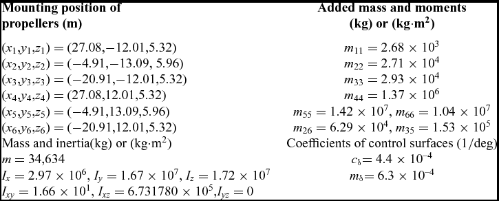
and their expressions can be found in Ref. Reference Wang, Fu, Duan and Shan25. The main parameters of this airship are given in Table 1.
Main parameters of an airship

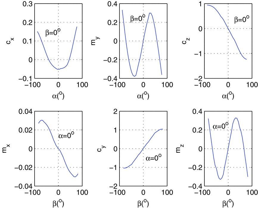
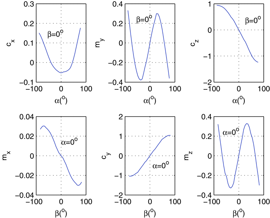
The aerodynamic coefficients of this airship are calculated according to computational fluid dynamics and then validated in the wind tunnel(Reference Wang, Fu, Duan and Shan25). The body aerodynamic coefficients with a single-flow angle are shown in Fig. 3, where cx , cy , cz are the aerodynamic force coefficients along x, y, z axes, mx , my , mz are the aerodynamic moment coefficients about x, y, z axes.
Aerodynamic coefficients of the airship body.
2.2 Actuator models
2.2.1 Equivalent aerodynamic model
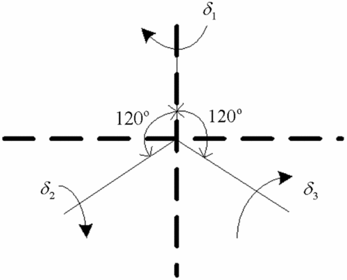
The empennages of inverse Y shape have three independent control surfaces U A = [δ1, δ2, δ3]Tas defined in Fig. 4. The airship has three independent control surfaces δ1, δ2 and δ3, where δ1 is used as the rudder andδ2 and δ3 are used as the elevator or rudder, but they can't be used as rudder and elevator together. When they are used as the rudder, there is coupled aileron deflection. For the convenience of aerodynamics calculations, they are transformed into equivalent synthetic aerodynamic surfaces: aileron, elevator and rudder in Equation (2).
Control surfaces definition.

 $$\begin{equation}
\left[ {\begin{array}{@{}*{1}{c}@{}} {{\delta _a}}\\
{{\delta _e}}\\
{{\delta _r}} \end{array}} \right] = {{{\bf M}}_\delta }\left[ {\begin{array}{@{}*{1}{c}@{}} {{\delta _{\rm{1}}}}\\
{{\delta _{\rm{2}}}}\\
{{\delta _{\rm{3}}}} \end{array}} \right]
\end{equation}$$
 $$\begin{equation*}
\begin{array}{@{}*{1}{c}@{}}
{ - {{30}^{o}} \le {\delta _i} \le {{30}^{o}}}\\
- {5^o}/s \le {{\dot{\delta }}_i} \le {5}^{o}/s \end{array}\quad
i = 1,2,{\rm{3}},
\end{equation*}$$
here M δ is the transform matrix between control surfaces and equivalent aerodynamic surfaces:
 $$\begin{equation*}
{{{\bf M}}_\delta }{\rm{ = }}\left[ {\begin{array}{@{}*{3}{c}@{}} {\rm{0}}&{\displaystyle\frac{{\sqrt 3 }}{2}}&{\displaystyle\frac{{\sqrt 3 }}{2}}\\[6pt] {\rm{0}}&{{\rm{ - }}\displaystyle\frac{{\sqrt 3 }}{2}}&{\displaystyle\frac{{\sqrt 3 }}{2}}\\[6pt] {{\rm{ - 1}}}&{\displaystyle\frac{{\rm{1}}}{2}}&{\displaystyle\frac{{\rm{1}}}{2}} \end{array}} \right]
\end{equation*}$$
The aerodynamic control force
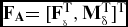 ${{{\bf F}}_{{\bf A}}}{\rm{ = [}}{{\bf F}}_{_\delta }^{\rm{T}},{{\bf M}}_\delta ^{\mathop{\rm T}\nolimits} {]^{\rm{T}}}$
in dynamic model (Equation (1)) are calculated according to equivalent synthetic aerodynamic surfaces:
 $$\begin{equation}
\begin{array}{@{}l@{}} {{{\bf F}}_\delta }{\rm{ = }}{[{q_\infty }{S_{\it ref}}{c_{x{\delta _a}}}{\delta _a},{q_\infty }{S_{\it ref}}{c_{y{\delta _r}}}{\delta _r},{q_\infty }{S_{\it ref}}{c_{z{\delta _e}}}{\delta _e}]^{\rm{T}}}\\ {{{\bf M}}_\delta }{\rm{ = [}}{q_\infty }{S_{\it ref}}{l_{\it ref}}{m_{x{\delta _a}}}{\delta _a},{q_\infty }{S_{\it ref}}{l_{\it ref}}{m_{y{\delta _e}}}{\delta _e},{q_\infty }{S_{\it ref}}{l_{\it ref}}{m_{z{\delta _r}}}{\delta _r}{]^{\rm{T}}}, \end{array}
\end{equation}$$
where q ∞ = 1/2ρV 2 is dynamic pressure of airflow, the reference surface is Sref = Vol 2/3 and reference length is lref = Vol 1/3 (Vol : airship volume).
2.2.2 Indirect control force model
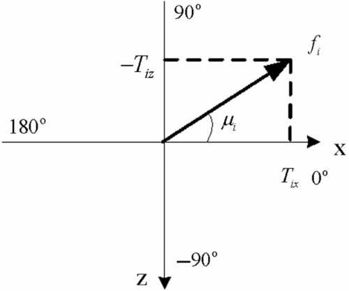
Each vectored propeller can change its thrust magnitude and direction independently as shown in Fig. 5. Hence, there are twelve control variables from the vectored propellers U T = [f 1, f 2, f 3, f 4, f 5, f 6, μ1, μ2, μ3, μ4, μ5, μ6]T, Each propeller is decoupled into two vertical components in the xoz plane of body-fixed frame,
 $$\begin{equation}
\begin{array}{@{}l@{}} {T_{ix}} = {f_i}\cos {\mu _i}\\ {T_{iz}} = - {f_i}\sin {\mu _i} \end{array}
\end{equation}$$
 $$\begin{equation*}
\begin{array}{@{}l@{}} 0 \le {f_i} \le 1960N,i = 1, \ldots ,6\\ - 100N/s \le {{\dot{f}}_i} \le 100N/s,i = 1, \ldots ,6\\ - {180^o} \le {\mu _i} \le {180^o}\\ - {30^o}/s \le {{\dot{\mu }}_i} \le {30^o}/s \end{array}
\end{equation*}$$
Vectored propeller definition.

Thus, the control vectored thrust vector F T in dynamic model (Equation (1)) can be described as:
 $$\begin{equation}
{{{\bf F}}_{{\bf T}}}{{\bf = PT}}
\end{equation}$$
 $$\begin{equation*}
\begin{array}{l}
{{{\bf F}}_{{\bf T}}} = {[{F_{Tx}},{F_{Ty}},{F_{Tz}},{F_{T\phi }},{F_{T\theta }},{F_{T\psi }}]^{\rm{T}}}\\
{{\bf T}} = {\left[ {\arraycolsep5pt\begin{array}{*{20}{c}} {{T_{1x}}}&{{T_{2x}}}&{{T_{3x}}}&{{T_{4x}}}&{{T_{5x}}}&{{T_{6x}}}&{{T_{1z}}}&{{T_{2z}}}&{{T_{3z}}}&{{T_{4z}}}&{{T_{5z}}}&{{T_{6z}}} \end{array}} \right]^{\rm{T}}},
\end{array}
\end{equation*}$$
 $$\begin{equation*}
{{\bf P}} = \left[ {\arraycolsep5pt\begin{array}{cccccccccccc} {\rm{1}}&{\rm{1}}&{\rm{1}}&{\rm{1}}&{\rm{1}}&{\rm{1}}&{\rm{0}}&{\rm{0}}&{\rm{0}}&{\rm{0}}&{\rm{0}}&{\rm{0}}\\ {\rm{0}}&{\rm{0}}&{\rm{0}}&{\rm{0}}&{\rm{0}}&{\rm{0}}&{\rm{0}}&{\rm{0}}&{\rm{0}}&{\rm{0}}&{\rm{0}}&{\rm{0}}\\ {\rm{0}}&{\rm{0}}&{\rm{0}}&{\rm{0}}&{\rm{0}}&{\rm{0}}&{\rm{1}}&{\rm{1}}&{\rm{1}}&{\rm{1}}&{\rm{1}}&{\rm{1}}\\ {\rm{0}}&{\rm{0}}&{\rm{0}}&{\rm{0}}&{\rm{0}}&{\rm{0}}&{{{{y}}_{\rm{1}}}}&{{{{y}}_{{2}}}}&{{{{y}}_{{3}}}}&{{{{y}}_{{4}}}}&{{{{y}}_{{5}}}}&{{{{y}}_{{6}}}}\\ {{{{z}}_{{1}}}}&{{{{z}}_{{2}}}}&{{{{z}}_{{3}}}}&{{{{z}}_{{4}}}}&{{{{z}}_{{5}}}}&{{{{z}}_{{6}}}}&{{{ - }}{{{x}}_{{1}}}}&{{{ - }}{{{x}}_{{2}}}}&{{{ - }}{{{x}}_{{3}}}}&{{{ - }}{{{x}}_{{4}}}}&{{{ - }}{{{x}}_{{5}}}}&{{{ - }}{{{x}}_{{6}}}}\\ {{{ - }}{{{y}}_{{1}}}}&{{{ - }}{{{y}}_{{2}}}}&{{{ - }}{{{y}}_{{3}}}}&{{{ - }}{{{y}}_{{4}}}}&{{{ - }}{{{y}}_{{5}}}}&{{{ - }}{{{y}}_{{6}}}}&{{0}}&{{0}}&{{0}}&{{0}}&{{0}}&{{0}} \end{array}} \right],
\end{equation*}$$
where T is the thrust components of six-vectored propellers in the xoz plane, called indirect control force vector, it is the connection between control thrust F
T
and the control variables of each propeller (fi
, μ
i
) by inverse calculation of Equation (4):
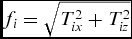 ${f_i} = \sqrt {T_{ix}^2 + T_{iz}^2} $
, μ
i
= atan2(Tix
, −T
iz); P is the control coefficient matrix of propellers, it is a constant coefficient matrix about mounting positions of propellers.
Here, indirect control force T is introduced, so the control coefficient matrix P is a constant matrix, the inverse of P always exists; thus, the pseudo-inverse-based actuator control allocation always has solution. The total input vector of this system is U = [UT T, UA T]T.
Since the vectored propellers are moving in the longitudinal plane, there is no lateral force generated, so FTy = 0; And the vertical force FTz can be generated for vertical altitude change. In this article, the altitude is only controlled by pitch motion, so FTz is only passively generated. As shown in the composite control design, only FTx is taken into consideration for forward velocity control.
3.0 CONTROL SYSTEM DESIGN
3.1 Guidance strategy
In the path-following control, the position and attitude [xc , yc , zc , Vc , ϕ c , θ c , ψ c ] must be controlled. Here (xc , yc , zc ) = RP(xi , yi , zi ) is the desired path point. For the given position tracking, the guidance strategy is:
 $$\begin{equation}
D = \sqrt {{{({y_c} - y)}^2} + {{({x_c} - x)}^2}} ,
\end{equation}$$\\
 $$\begin{equation}
{\psi _c} = a\tan 2({y_c} - y,{x_c} - x),
\end{equation}$$\\
 $$\begin{equation}
{\phi _c} = {\rm{0}},
\end{equation}$$
 $$\begin{equation}
\left\{ \begin{array}{@{}l@{}} \arraycolsep5pt\begin{array}{*{20}{c}} {{V_c} = {\rm{def}}}&{D > \Delta D} \end{array}\\ \arraycolsep5pt\begin{array}{*{20}{c}} {{V_c} = \frac{D}{{\Delta D}}{\rm{def}}}&{D < \Delta D} \end{array} \end{array} \right.,
\end{equation}$$
where def is any constant defined by user, ΔD is a specified distance from the destination point, and for path-following and altitude control, it is defined as:
 $$\begin{equation}
{V_c} = def
\end{equation}$$
The same guidance strategy is applied to the pitch angle planning for altitude control
 $$\begin{equation}
\left\{ \begin{array}{@{}l@{}} \arraycolsep5pt\begin{array}{*{20}{c}} {{\theta _c} = {\rm{def}}}&{{D_z} > \Delta {D_z}} \end{array}\\ \arraycolsep5pt\begin{array}{*{20}{c}} {{\theta _c} = {k_{\theta z}}({z_c} - z)}&{{D_z} < \Delta {D_z}} \end{array} \end{array} \right.,
\end{equation}$$
where Dz is the value of altitude change, ΔDz is a specified range from the destination altitude. So the nominal climbing velocity is
 $$\begin{equation}
{\dot{z}_c} = {\rm{ - }}{V_c}\sin {\theta _c}
\end{equation}$$
3.2 Basic controller design
For the safety reason, the incremental PID is chosen for controller design in real application.
The velocity model can be approximated as a first-order inertial model, so a PI controller is adopted, where integral term is used to compensate forward aerodynamic drag.
 $$\begin{equation}
\begin{array}{@{}l@{}} {e_u} = {V_c} - {V_i}\\ {T_0} = \frac{1}{2}\rho V_{\rm{0}}^2{s_{{\rm{ref}}}}{c_D}\\ \Delta T = {k_{pu}}({e_u} - {e_{u1}}) + {k_{iu}}{e_u}\\ {F_{Tx}} = {T_0} + \Delta T \end{array},
\end{equation}$$
where V 0 is the trim velocity, Vi is the current ground speed, and e u1 is the tracking error of last control period. The pitch motion can be approximated as a two-order oscillation model, so a PID controller is adopted, the same controller structure is designed for the roll motion to keep roll angle to zero, though there is a stabilising moment from the gravity:
 $$\begin{equation}
\begin{array}{@{}l@{}} {e_\theta } = {\theta _c} - \theta \\ \Delta {M_\theta } = {k_{p\theta }}({e_\theta } - {e_{\theta 1}}) + {k_{d\theta }}({e_\theta } - 2{e_{\theta 1}} + {e_{\theta 2}}) + {k_{i\theta }}{e_\theta }\\ {M_\theta } = {M_\theta }_0 + \Delta {M_\theta } \end{array},
\end{equation}$$\\
 $$\begin{equation}
\begin{array}{@{}l@{}} {e_\phi } = {\phi _c} - \phi \\ \Delta {M_\phi } = {k_{p\phi }}({e_\phi } - {e_{\phi 1}}) + {k_{d\phi }}({e_\phi } - 2{e_{\phi 1}} + {e_{\phi 2}}) + {k_{i\phi }}{e_\phi }\\ {M_\phi } = {M_{\phi 0}} + \Delta {M_\phi } \end{array}
\end{equation}$$
The yaw motion can be approximated as a two-order integral system, so a PD controller is used:
 $$\begin{equation}
\begin{array}{@{}l@{}} {e_\psi } = {\psi _c} - \psi \\ \Delta {M_\psi } = {k_{p\psi }}({e_\psi } - {e_{\psi 1}}) + {k_{d\psi }}({e_\psi } - 2{e_{\psi 1}} + {e_{\psi 2}})\\ {M_\psi } = {M_\psi }_0 + \Delta {M_\psi } \end{array},
\end{equation}$$
where M θ 0, M ϕ0 and M ψ 0 are control moments of last control period.
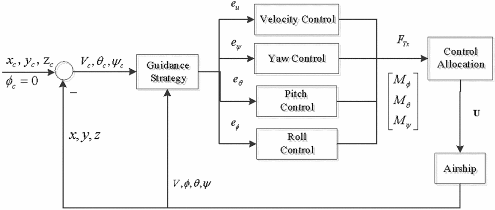
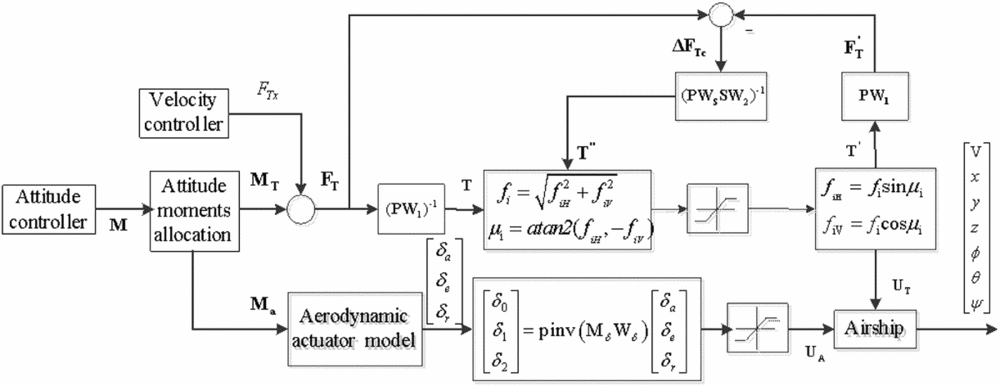
The overall control system structure is shown in Fig. 6. The control allocation model, which will be discussed in next two sections, includes attitude moment allocation and actuator reconfigurable allocation.
Basic structure of control system.

3.3 Attitude moment allocation
As mentioned before, both the aerodynamic surfaces and the vectored propellers can generate the attitude control moments. The attitude moments generated from the aerodynamic surfaces are affected by dynamic pressure. For an airship, the steady forward airspeed is slow, especially when hovering at fixed point, the airship's response to aerodynamic surface is slow(Reference Zhang, Duan and Chen26). However, propellers are less affected by airspeed and airship's response is fast under the action of vectored propellers(Reference Zhang, Duan and Chen26). Therefore, for the attitude moment allocation, the aerodynamic surfaces have high authority over the vectored propellers at high airspeed in consideration of energy consumption; the vectored propellers have high authority at low airspeed in consideration of manoeuverability(Reference Di, Han and Yao8,Reference Zhang, Duan and Chen26) . Such a control allocation strategy of attitude moments between the aerodynamic surfaces and the vectored propellers can be deduced according to different airspeed,
 $$\begin{equation}
\left\{ \begin{array}{@{}l@{}} {w_{\rm{a}}} = (V - {V_l})/({V_h} - {V_l}),{w_p} = 1 - {w_a},{V_l} < V < {V_h}\\ {w_p} = 0,{w_a} = 1,V \ge {V_h}\\ {w_p} = 1,{w_a} = 0,V \le {V_l} \end{array} \right.,
\end{equation}$$
where wa
and wp
are weights of aerodynamic moment and thrust moment, respectively, Vh
and Vl
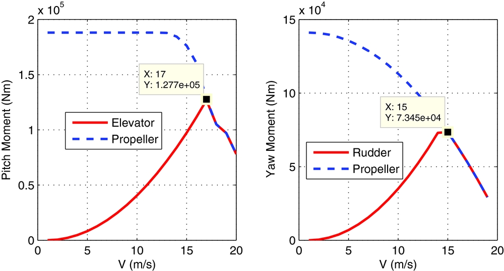
are two critical airspeeds for weight calculation. Here, the two critical airspeeds are determined by the evaluation of maximum moment outputs for a given airspeed, where the airspeed is kept by the propellers; the remaining thrust is used for pitch or yaw motion. The maximum attitude moments are compared between the propellers and aerodynamic surfaces in Fig. 7. The maximum thrust output of every propeller is 1960 N, the equivalent maximum aerodynamic deflections
 ${\delta _{e\max }} = \frac{{\sqrt {\rm{3}} }}{2}| {{\delta _{2\max }}} | + \frac{{\sqrt {\rm{3}} }}{2}| {{\delta _{3\max }}} | \approx {\rm{52}}^\circ $
and
 ${\delta _{r\max }} = | {{\delta _{1\max }}} | + \frac{{\rm{1}}}{2}| {{\delta _{2\max }}} | + \frac{{\rm{1}}}{2}| {{\delta _{3\max }}} | = {\rm{60}}^\circ $
are deduced from Equation (2). The maximum aerodynamic moments calculated from Equation (3) increase as the airspeed increases; however, the maximum thrust moments calculated from Equation (5) decrease as the airspeed increases; It can be seen, that the aerodynamic moment generated is comparable to that of propellers at speed of 17 m/s in pitch and 15 m/s in yaw, respectively.
Maximum moment comparison between propellers and aerodynamic surfaces.
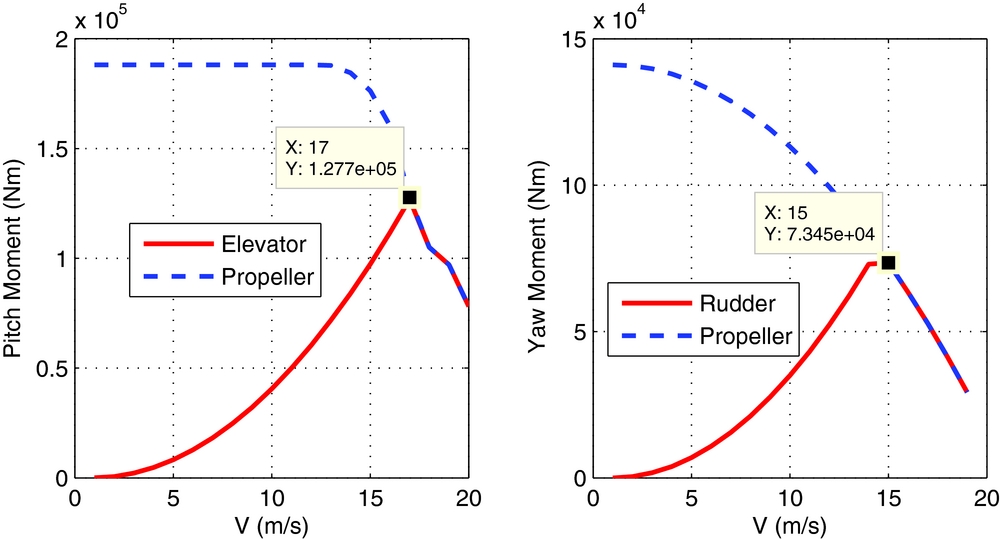
For this airship, the maximum airspeed is 15 m/s, such Vh = 15m/s and Vl = 0m/s are chosen in Equation (17), it means that the vectored propellers and aerodynamic surfaces participate in attitude control in the whole airspeed range.
The attitude control moments M ϕ, M θ and M ψ are obtained from controller Equations (14)-(16). Then they are divided into aerodynamic moments M a = [M δa , M δe , M δr ]T and thrust moments M T = [F Tϕ, F Tθ, F Tψ]T by integrated weight matrix.
 $$\begin{equation}
{{\bf M}} = \left[ \begin{array}{@{}l@{}} {{{\bf M}}_{{\bf a}}}\\ {{{\bf M}}_{{\bf T}}} \end{array} \right] = \left[ \begin{array}{@{}l@{}} {M_{\delta a}}\\ {M_{\delta e}}\\ {M_{\delta r}}\\ {F_{T\phi }}\\ {F_{T\theta }}\\ {F_{T\psi }} \end{array} \right] = \left[ \begin{array}{@{}l@{}} {\rm{diag[}}{w_a},{w_a},{w_a}]\\ {\rm{diag}}[{w_p},{w_p},{w_p}] \end{array} \right]\left[ \begin{array}{@{}l@{}} {M_\phi }\\ {M_\theta }\\ {M_\psi } \end{array} \right]
\end{equation}$$
3.4 Reconfigurable actuator allocation
After the attitude moments allocation, there is a further actuator allocation of aerodynamic moments among multi-aerodynamic surfaces and allocation of thrust moments and forward thrust among multi-vectored propellers. The actuator control allocation system is designed based on weighted pseudo-inverse method. The weights taken here are indicating the actuator's working states: normal or failed. The reconfigurable control system can reallocate the actuators simply by modifying their individual weights; thus, system reconfiguration is quick. This system is also easy to implement due to the analytic solution of allocation based on pseudo-inverse.
3.4.1 Reconfigurable allocation among multi-surfaces
Given the aerodynamic moments, the deflection angles of synthetic aerodynamic surfaces can be obtained from the dynamic model in Equation (3), then the independent control surfaces are deduced from the inverse transform of Equation (2). The weight matrix of three control surfaces is: W δ = diag[w δ1, w δ2, w δ3], w δi (i = 1, 2, 3) is the weight in which 1 represents normal deflection and 0 represents stuck at any initial deflection angle. After the attitude control, the fault detection will give the weight matrix. Then, the pseudo-inverse is implemented to realise actuator reconfiguration.
 $$\begin{equation}
\left[ {\begin{array}{@{}*{1}{c}@{}} {{\delta _{\rm{1}}}}\\ {{\delta _{\rm{2}}}}\\ {{\delta _{\rm{3}}}} \end{array}} \right] = {\rm{pinv}}\left( {{{{\bf M}}_\delta } \cdot {{{\bf W}}_\delta }} \right)\left[ {\begin{array}{@{}*{1}{c}@{}} {{\delta _a}}\\ {{\delta _e}}\\ {{\delta _r}} \end{array}} \right]
\end{equation}$$
3.4.2 Reconfigurable allocation among multi-propellers
For the general implementation of the propeller allocation, three diagonal weight matrices are adopted. Three kinds of weights are combined together to represent the all possible faults of vectored propeller: magnitude deficiency, vectored angle stuck and actuator failed.
The first weight matrix is W 1 , which denotes the state of every non-stuck propeller. As a result, Equation (5) is expanded to:
 $$\begin{equation}
{{{\bf F}}_{{\bf T}}}{{\bf = P}}{{{\bf W}}_{{\bf 1}}}{{\bf T}},
\end{equation}$$
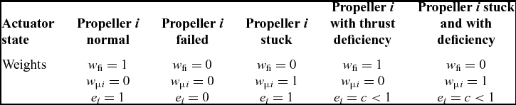
where W 1 = diag[e 1 w f1 e 2 w f2 e 3 w f3 e 4 w f4 e 5 w f5 e 6 w f6 e 1 w f1 e 2 w f2 e 3 w f3 e 4 w f4 e 5 w f5 e 6 w f6], and w fi is propeller weight; and w fi = 1 is the weight of the non-stuck actuator. If w fi = 0, the actuator encounters fault one and may either be stuck in a vectored angle or total failed. ei is the weight of maximum thrust of each deficient propeller.
 $$\begin{equation}
{F_T}_{\it imaxf} = {e_i} \cdot {F_{{\it Ti}\max }},
\end{equation}$$
where F Timax is the maximum magnitude of every normal propeller; and FT imaxf is the real maximum thrust under thrust deficiency.
In a stuck fault, the trigonometric function matrix of a vectored angle must be separated with propeller magnitude. Thus, Equation (5) is rewritten again as
 $$\begin{equation}
{{{\bf F}}_{{\bf T}}}{{\bf = PSf}}
\end{equation}$$
 $$\begin{equation*}
\begin{array}{@{}*{6}{c}@{}} {{{\bf f}} = {{\left[ {\arraycolsep5pt\begin{array}{*{20}{c}} {{f_1}}&{{f_2}}&{{f_3}}&{{f_4}}&{{f_5}}&{{f_6}} \end{array}} \right]}^{\rm{T}}}}\\ {{{\bf S}} = [{\it diag}\arraycolsep5pt\begin{array}{*{20}{c}} {[\sin {\mu _{10}}}&{\sin {\mu _{20}}}&{\sin {\mu _{30}}}&{\sin {\mu _{40}}}&{\sin {\mu _{50}}}&{\sin {\mu _{60}}]} \end{array};,}\\ {{\it diag}[ - \cos {\mu _{10}}, - \cos {\mu _{20}}, - \cos {\mu _{30}}, - \cos {\mu _{40}}, - \cos {\mu _{50}}, - \cos {\mu _{60}}]]} \end{array}
\end{equation*}$$
where μ i0 denotes the position at which the propeller is stuck.
In failure cases, the last two weight matrices are incorporated into Equation (22) as
 $$\begin{equation}
{{{\bf F}}_{{\bf T}}}{{\bf = P}}{{{\bf W}}_{{\bf s}}}{{\bf S}}{{{\bf W}}_{{\bf 2}}}{{\bf f}},
\end{equation}$$
where W 2 = diag[e 1(1 − w f1) e 2(1 − w f2) e 3(1 − w f3) e 4(1 − w f4) e 5(1 − w f5) e 6(1 − w f6)] indicates the weight of the propeller as a result of any failure, W s = diag[w μ1 w μ2 w μ3 w μ4 w μ5 w μ6 w μ1 w μ2 w μ3 w μ4 w μ5 w μ6] denotes the weight of a stuck propeller, and w μi is the weight of the vectored angle. If w fi = 0 and w μi = 1, the failure is stuck at a certain vectored angle, but with the thrust magnitude. If w fi = 0 and w μi = 0, the propeller has failed completely and no action can be taken.
Thus, the total thrust force can be determined by:
 $$\begin{equation}
{{{\bf F}}_{{\bf T}}}{{\bf = P}}{{{\bf W}}_{{\bf 1}}}{{\bf T + P}}{{{\bf W}}_{{\bf s}}}{{\bf S}}{{{\bf W}}_{{\bf 2}}}{{\bf f}}
\end{equation}$$
The first item on the right side of the Equation (24) represents the contribution of non-stuck propellers, and the second item indicates the contribution of the failed propellers. By using the weight matrix W 1 , the propeller deficiency can be considered. By introducing the weight matrixes W s and W 2, the propeller stuck can be considered. By using the weight matrixes W 1 , W 2 and W s together, the failed propeller can be considered. In this controller, the indirect control force T in Equation (24) is maintained, which guarantees the existence of the pseudo-inverse of constant matrixes PW 1 and PW s SW 2 as long as the fault situations were given. So there always exists solution to the controller. Table 2 shows the relationship of actuator failure with the weights.
Actuator state and weights

The reconfigurable actuator allocation structure is shown in Fig. 8. The redistributed pseudo-inverse technique is taken between the normal actuators and the actuators of any failure where T' is the indirect control force vector taken by the non-stuck propellers, T'' is the indirect control force vector taken by stuck propellers. ΔF Tc is the moment difference of desired moment with the moment of non-stuck propellers and it will be compensated by other faulty actuators as long as the control ability is guaranteed. In the control allocation, the non-stuck actuators have the priority to the fault actuator in actuation to achieve better performance and less energy consumption. If the commanded force cannot be satisfied, the reconfigurable controller takes effect by changing its weights to adaptation the failure of fault actuators, then reallocates residual force ΔF Tc among the fault actuators, and induces compensation force T''. The fault detection model is not designed in this article, so the failures are defined in advance. The system retains full controllability as long as remaining actuators still have the actuation ability.
Reconfigurable actuator allocation structure.

4.0 COMPOSITE CONTROL SIMULATION
In this section, position control, trace tracking and altitude control are implemented to validate the proposed strategies. The attitude moment allocation is achieved under different speeds and the reconfigurable actuator allocation is conducted under different actuator faults.
4.1 Control moment allocation under different airspeeds
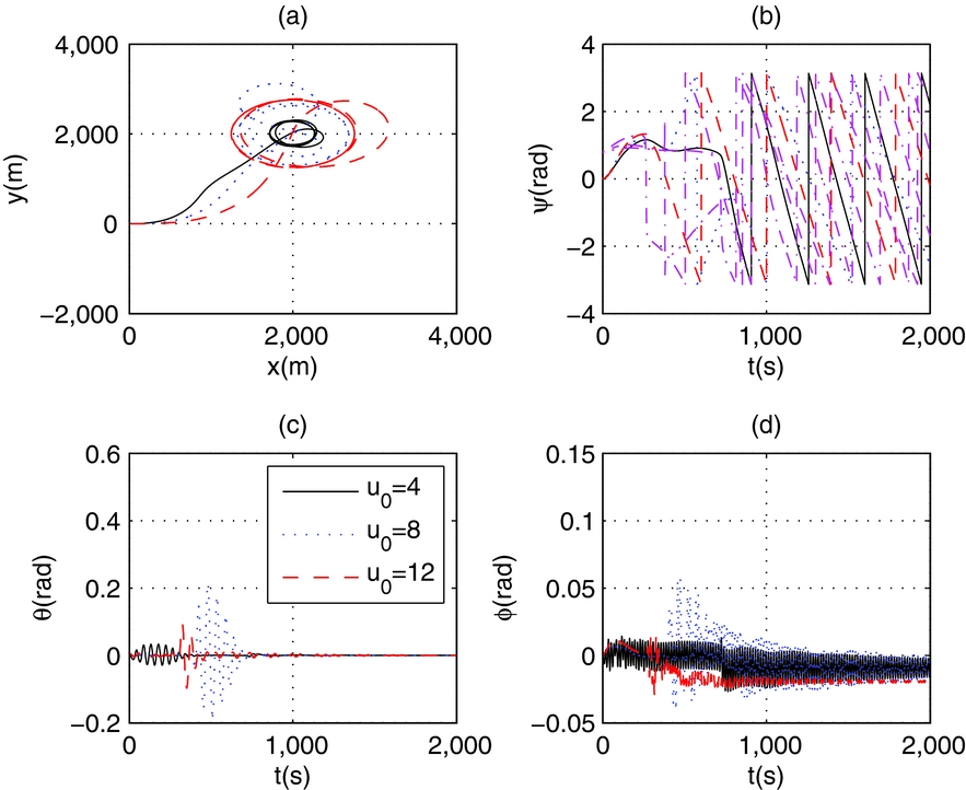
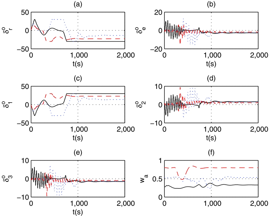
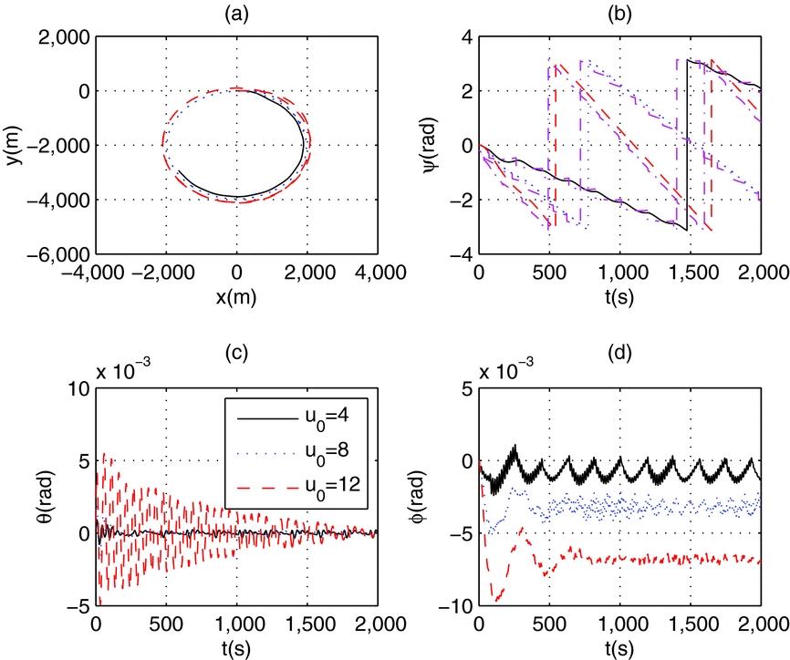
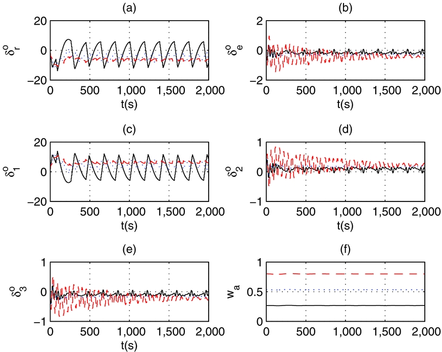
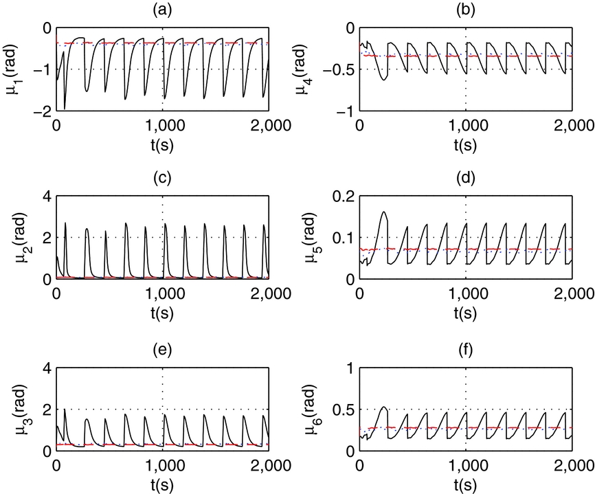
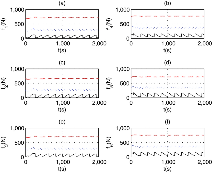
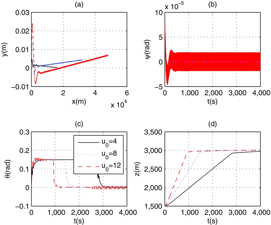
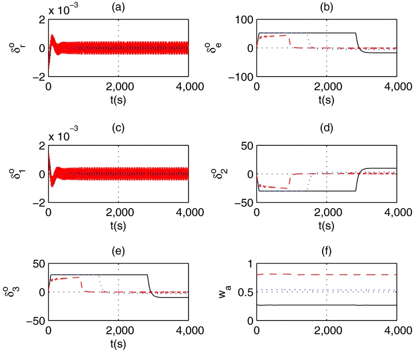
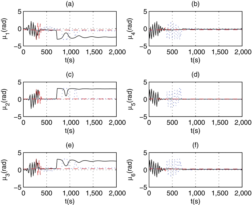
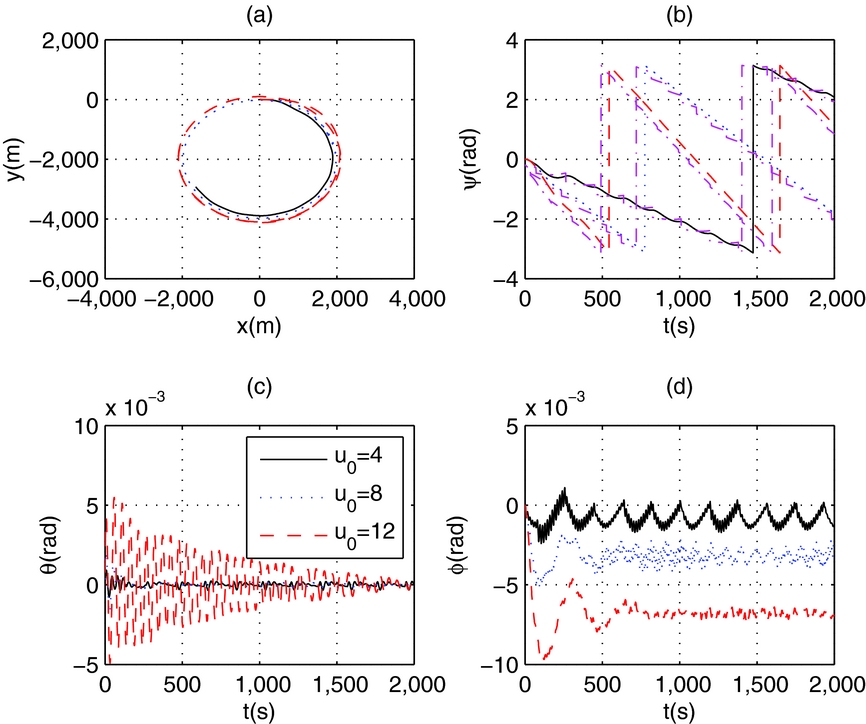
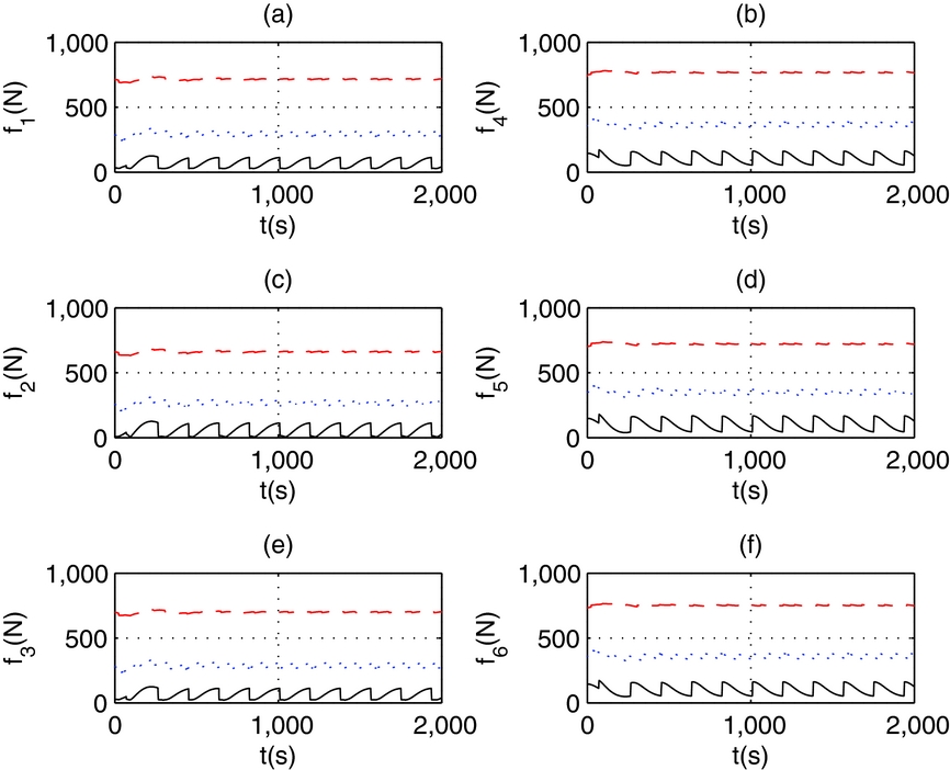
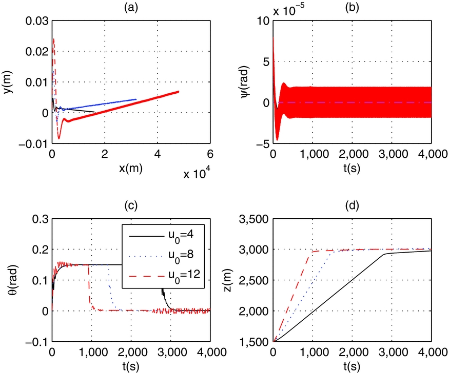
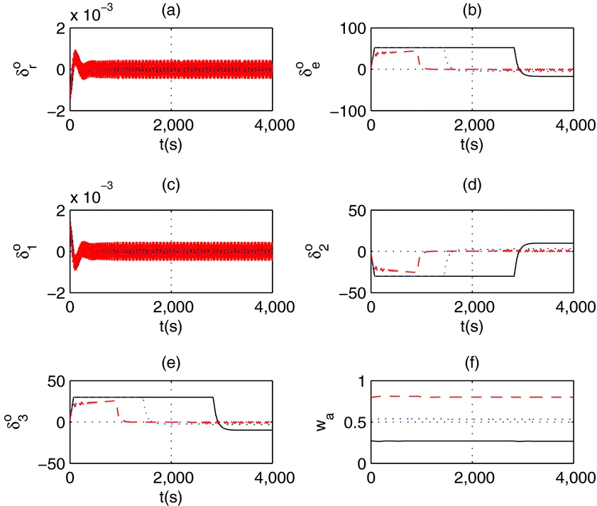
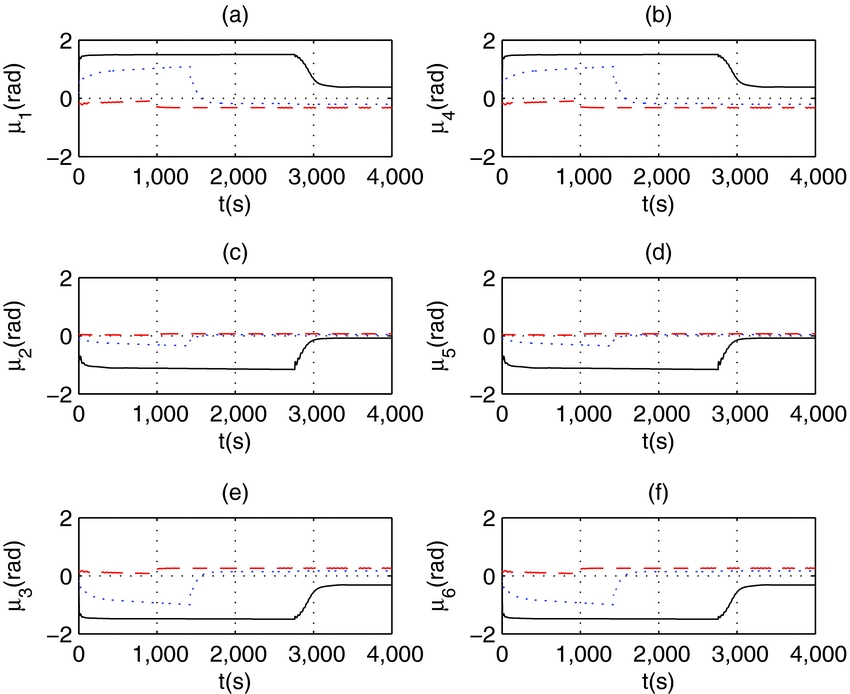
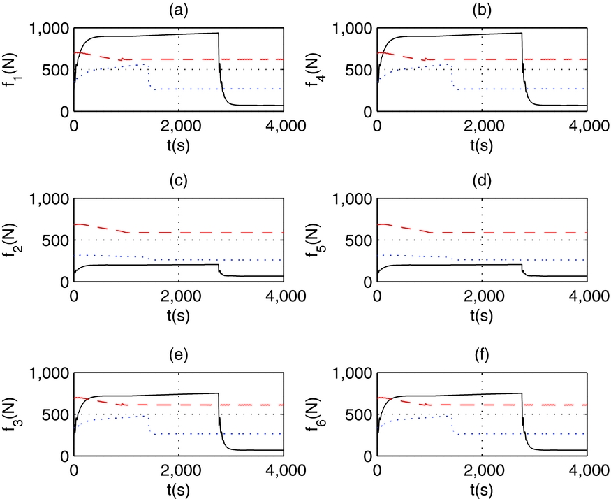
Simulation results of composite control in normal actuator situation are shown in Figs 9–12 for position control, Figs 13–16 for trace tracking and Figs 17–20 for altitude control, respectively. And it is conducted under different trim airspeeds: u0 = 4 m/s, u0 = 8 m/s and u0 = 12 m/s. Figs 10–12 show the actuator outputs for position control, Figs 14–16 show the actuator outputs for trace tracking, and Figs 18–20 show the actuator outputs of altitude control. The moment allocation weights of aerodynamic surfaces are shown in Figs 10, 14 and 18, respectively. From simulation results we can see, the attitude moment allocation strategy can regulate moment allocation weights in different airspeeds. The responses of composite control are smooth under different airspeeds, the output of every actuator is limited in its hard constrains.
States in position control of normal cases.
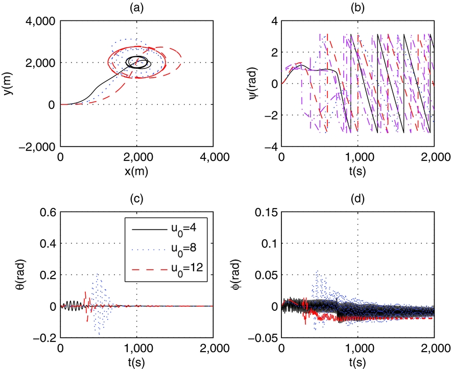
Control surfaces and moment allocation weights in position control of normal cases.

Vectored angles in position control of normal cases.
Thrusts in position control of normal cases.

States in trace tracking of normal cases.
Control surfaces and moment allocation weights in trace tracking of normal cases.

Vectored angles in trace tracking of normal cases.

Thrusts in trace tracking of normal cases.
States in altitude control of normal cases.
Control surfaces and moment allocation weights in altitude control of normal cases.
Vectored angles in altitude control of normal cases.
Thrusts in altitude control of normal cases.
In position tracking, with increasing of airspeed, the diameter of hover circle increases (Fig. 9(a)); the thrusts required also increase (Fig. 12(a)); the aerodynamic deflections decrease (Fig. 10(a)), at low airspeed, u0 = 4 m/s, the rudder reaches full position for heading control. The attitude allocation weights are varied with variation of airspeed (Fig. 10(f)).
In trajectory tracking, the tracking traces do not have much difference, with increasing of the airspeed, the aerodynamic deflections decrease (Fig. 14), the thrusts required increase (Fig. 16), The attitude allocation weights are almost unchanged with variation of airspeed (Fig. 14(f)).
In altitude control, the pitch angle is consistent with altitude change (Fig. 17), the maximum pitch angel is limited by defined constant value in guidance algorithm of Equation (11). The climbing velocity increases with the increasing of airspeed, so the climbing time is shorten with high airspeed (Fig. 17(d)). Elevator deflection increases as the airspeed decreases (Fig. 18), such that, at high speed, the difference of thrust between climbing and cruising is small (Fig. 20); the attitude allocation weights are almost unchanged with the variation of airspeed in the steady climbing and final cruising phases as long as the airspeed is stable (Fig. 18(f)).
4.2 Reconfigurable actuator allocation under different faults
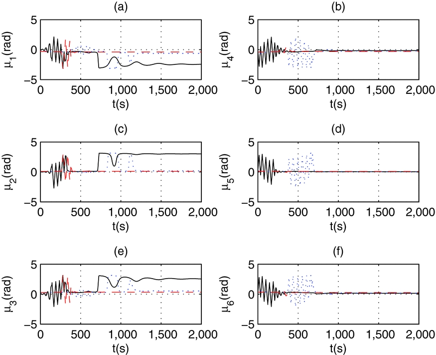
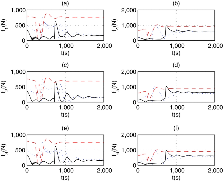
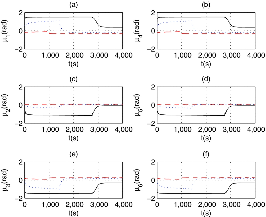
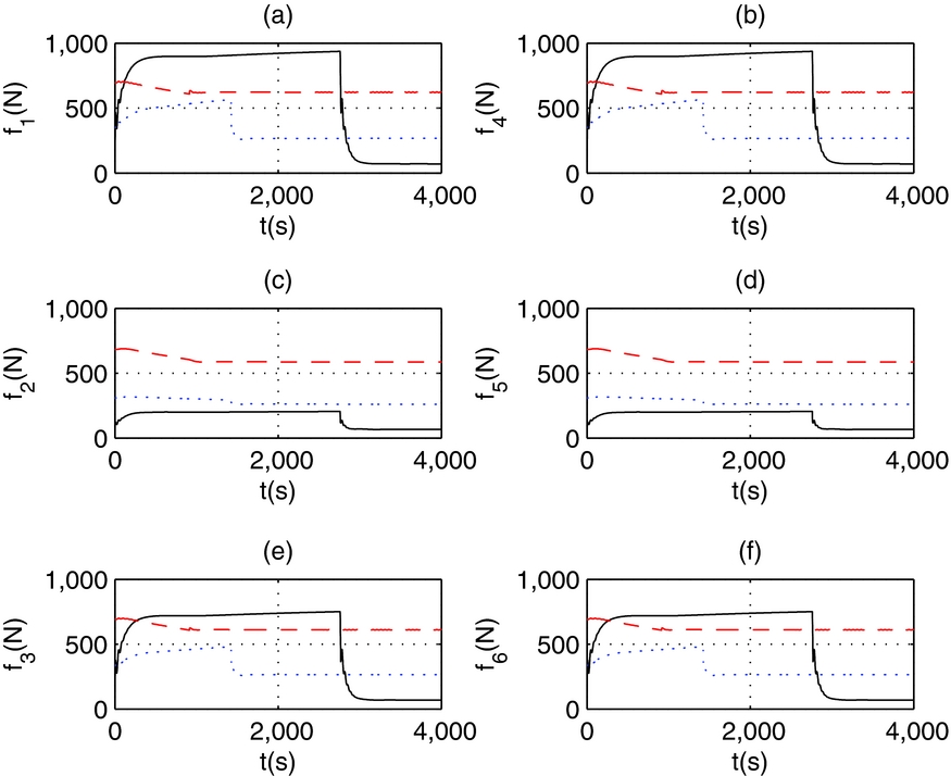
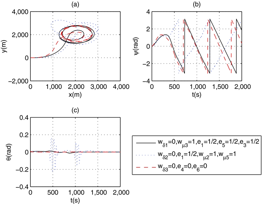
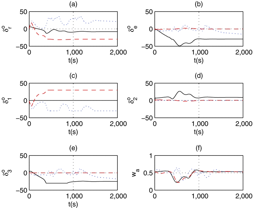
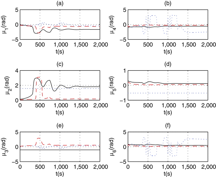
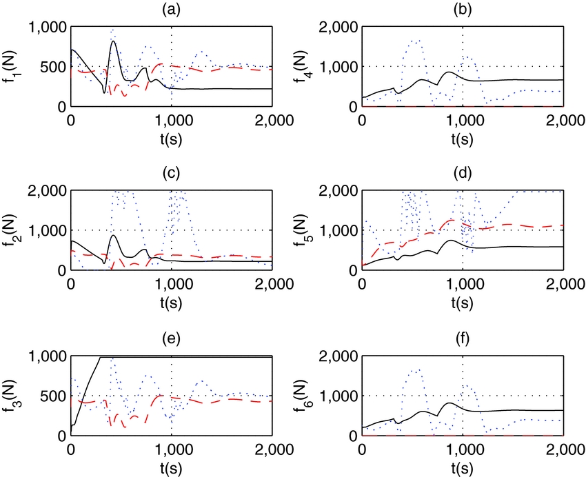
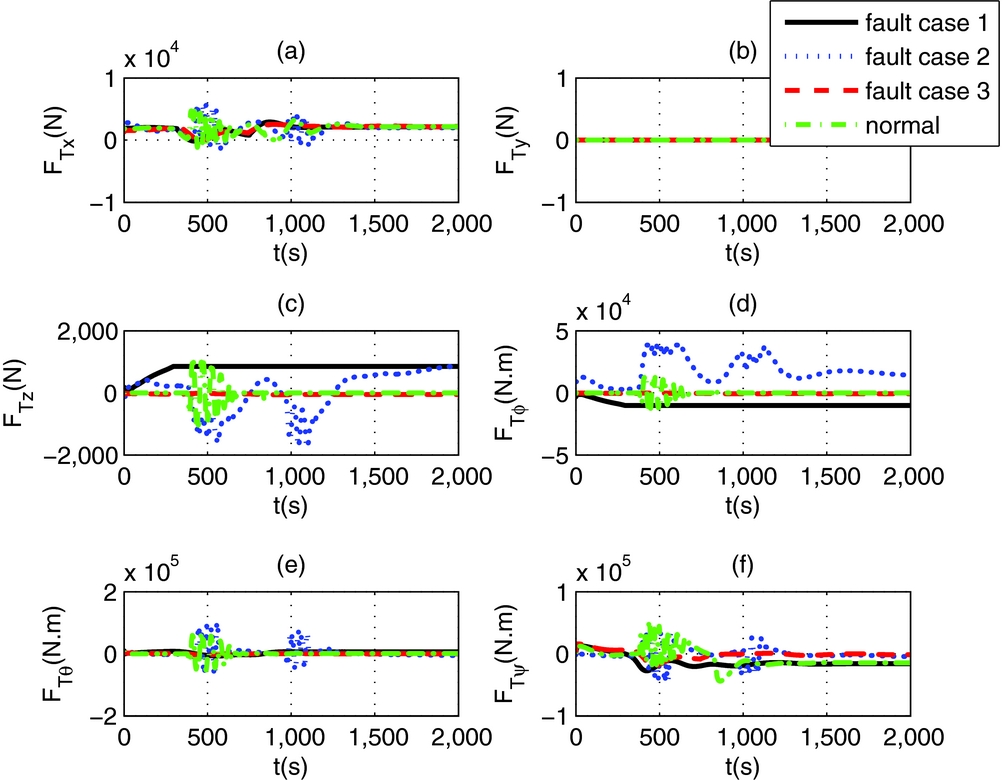
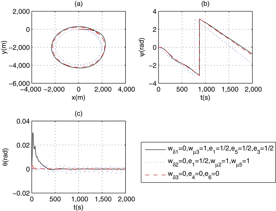
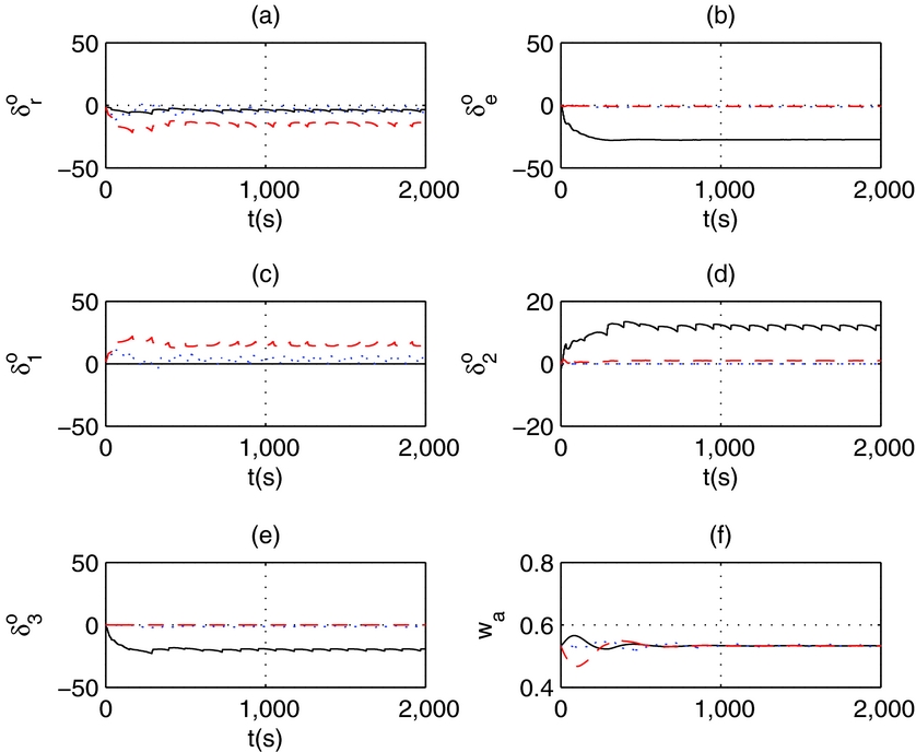
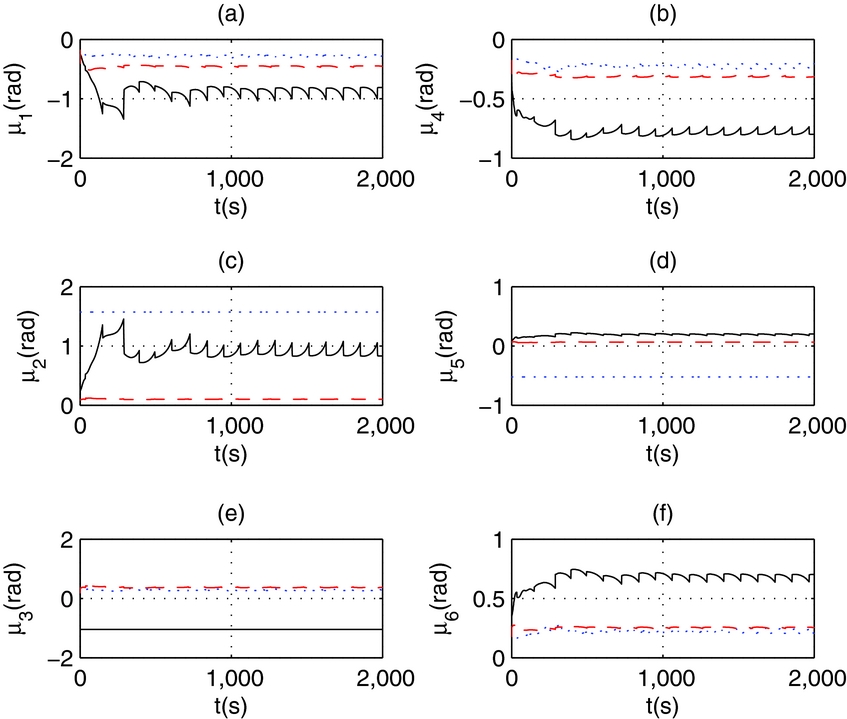
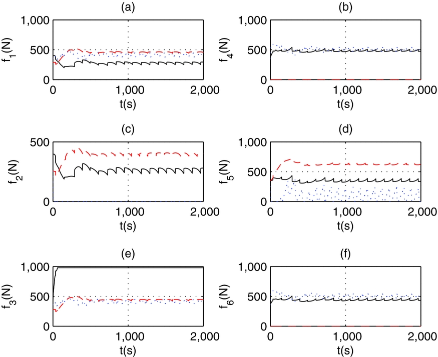
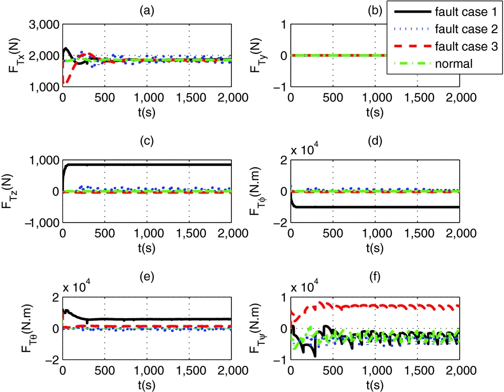
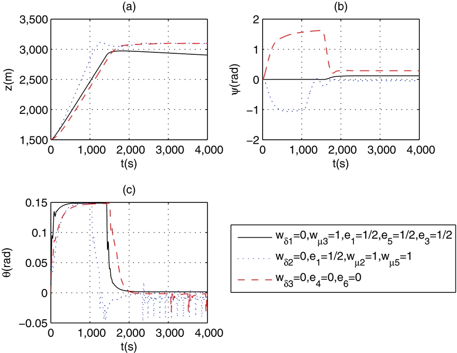
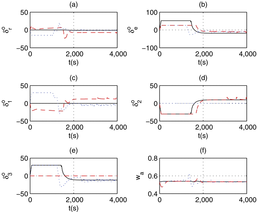
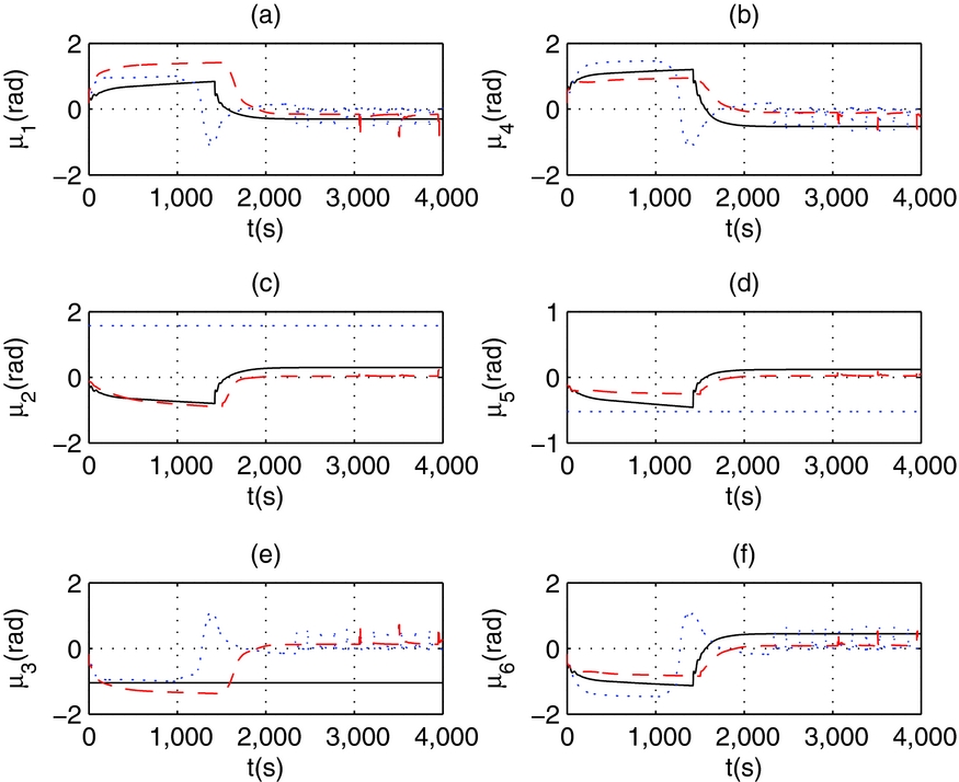
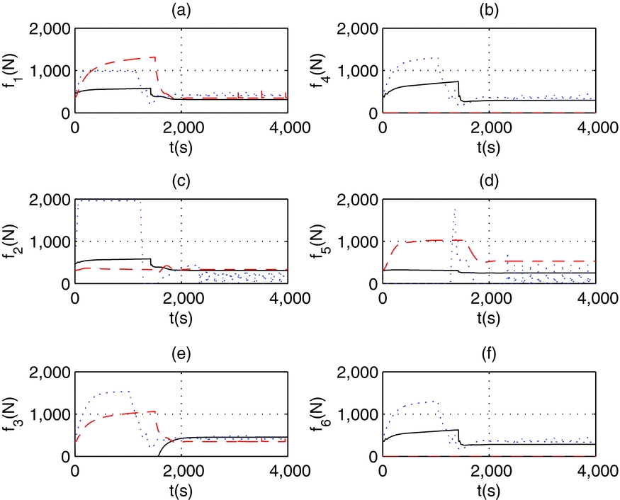
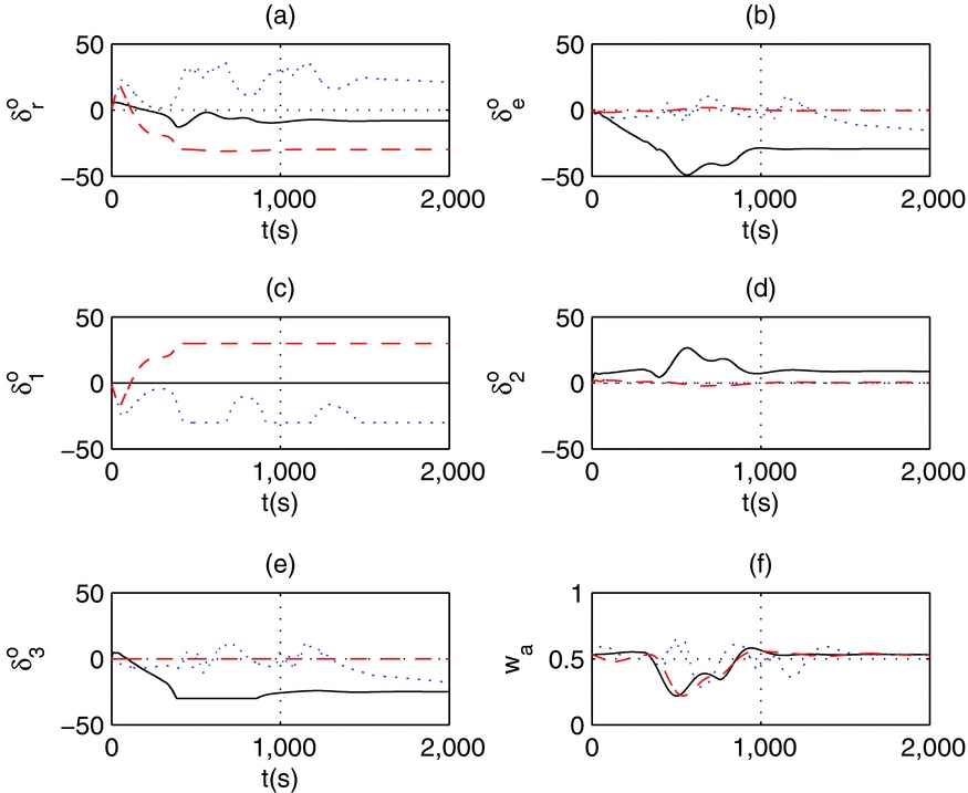
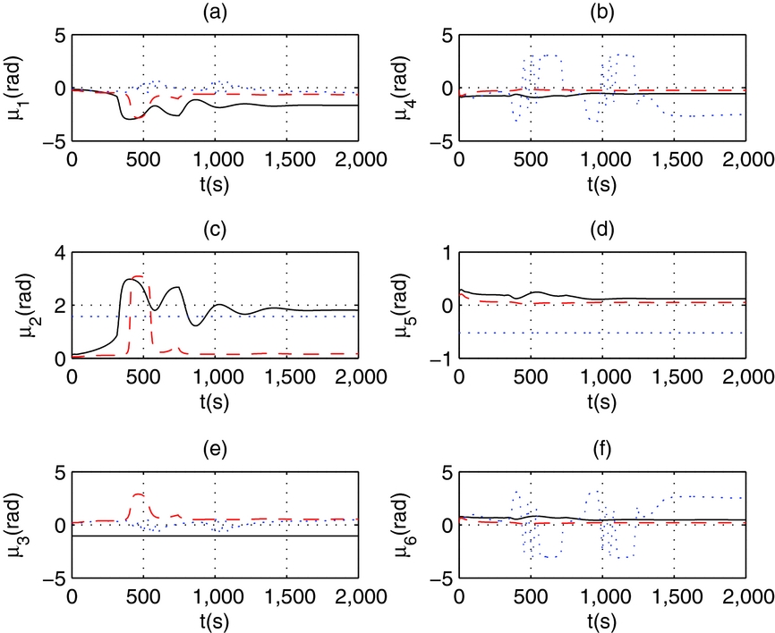
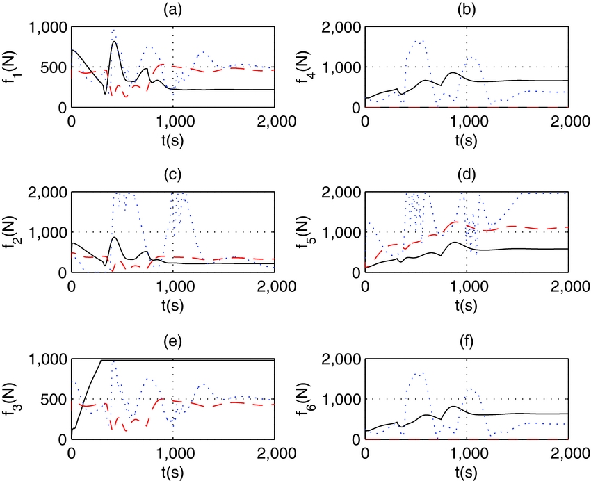
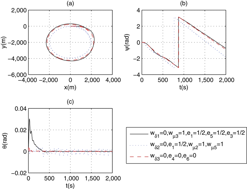
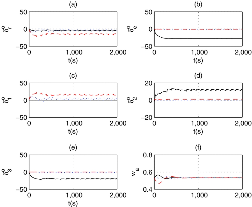
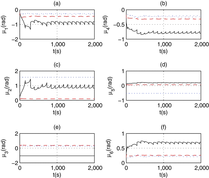
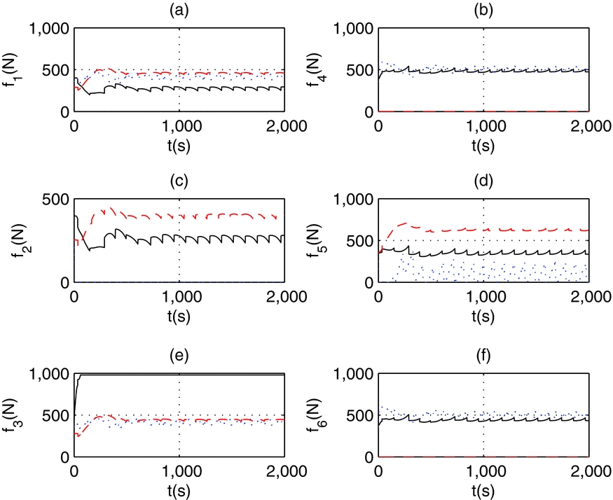
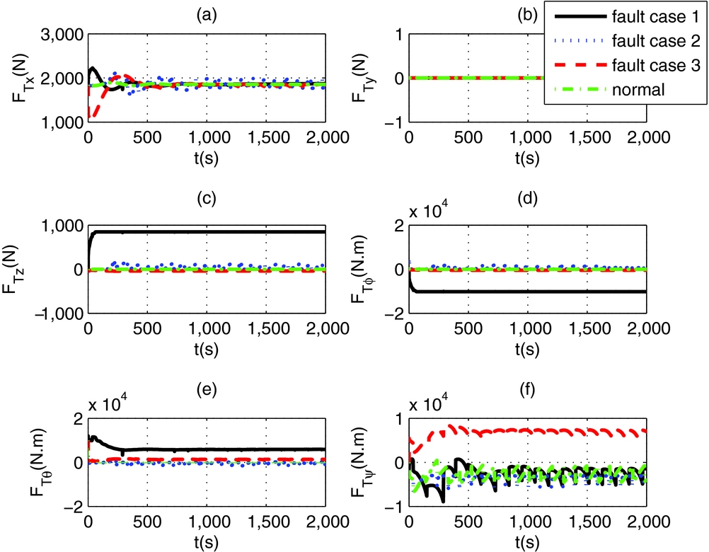
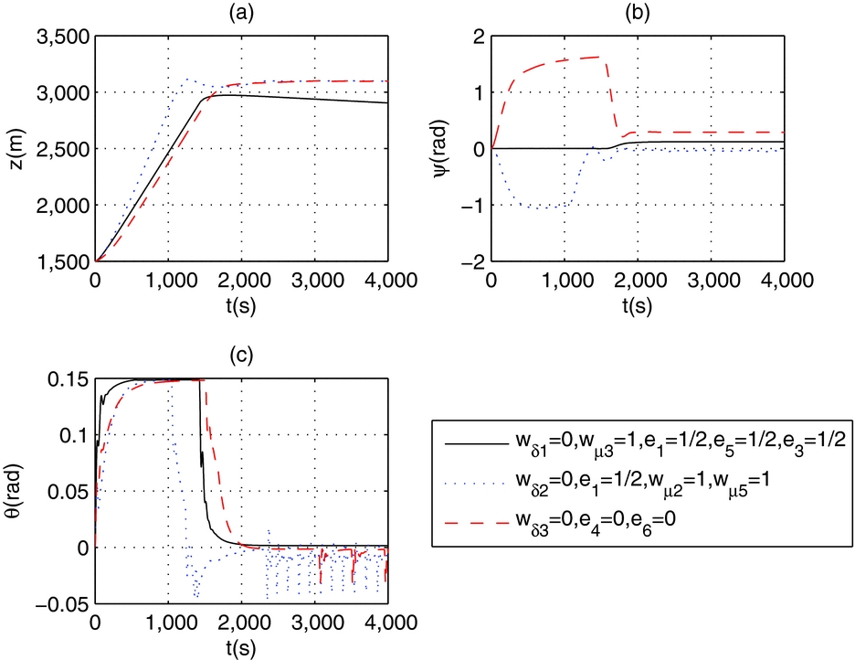
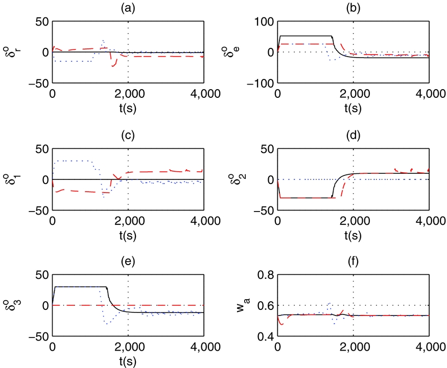
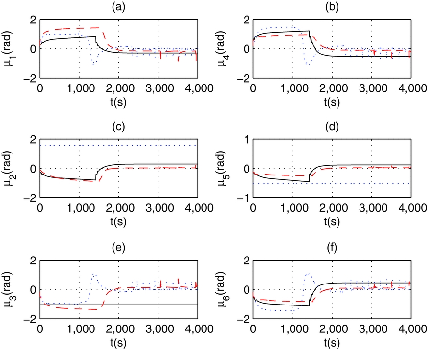
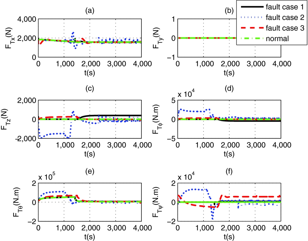
For a given airspeed, simulation results of composite control under actuator failure cases are shown in Figs 21, 26 and 31 for position control, trace tracking and altitude control, respectively. The trim airspeed is V 0 = 8 m/s. And it is conducted under three different failure cases. In the first case, the fault weights are [w δ1 = 0,w μ3 = 1, e 1 = 1/2, e 3 = 1/2, e 5 = 1/2], it means that the control surface 1 and propeller 3 are stuck, propellers 1,3, and 5 have a thrust deficiency of 1/2; In the second failure case, the fault weights are [w δ2= 0,w μ2= 1,w μ5= 1,e 1= 1/2], which means that control surface 2 and propellers 2 and 5 are stuck, and propeller 1 has a thrust deficiency of 1/2. In the third case, the fault weights are [w δ3= 0,e 4= 0,e 6= 0], it means that control surface 3 is stuck and propellers 4 and 6 are totally failed. The stuck positions of all fault actuators are μ20= 90o, μ30= -60o, μ50= -30o and δ10=0o, δ20=0o, δ30=0o. Figures 22–24 show the actuator outputs for position control, Figs 27–29 show the actuator outputs for trace tracking, and Figs 32–34 show the actuator outputs of altitude control. The moment allocation weights of aerodynamic surfaces are shown in Figs 22(f), 27(f) and 32(f), respectively. Figures 25, 30 and 35 give the control force allocation of multi-propellers in body-fixed frame under different actuator configurations. From the simulation results we can see, the reconfigurable actuator allocation strategy can reallocate the actuator in case of failures. The responses of composite control are smooth under different failures, the output of every actuator is limited in its hard constrains.
States in position control of failure cases.

Control surfaces and moment allocation weights in position control of failure cases.
Vectored angles in position control of failure cases.
Thrusts in position control of failure cases.
Control force allocation of propellers in position control.

States in trace tracking of failure cases.
Aerodynamic deflections in trace tracking of failure cases.
Vectored angles in trace tracking of failure cases.
Thrusts in trace tracking of failure cases.
Control force allocation of propellers in trace tracking of failure cases.
States in altitude control of failure cases.
Aerodynamic deflections in altitude control of failure cases.
Vectored angles in altitude control of failure cases.
Thrusts in altitude control of failure cases.

Control force allocation of propellers in altitude control.
4.2.1 Compensation among multi-actuators
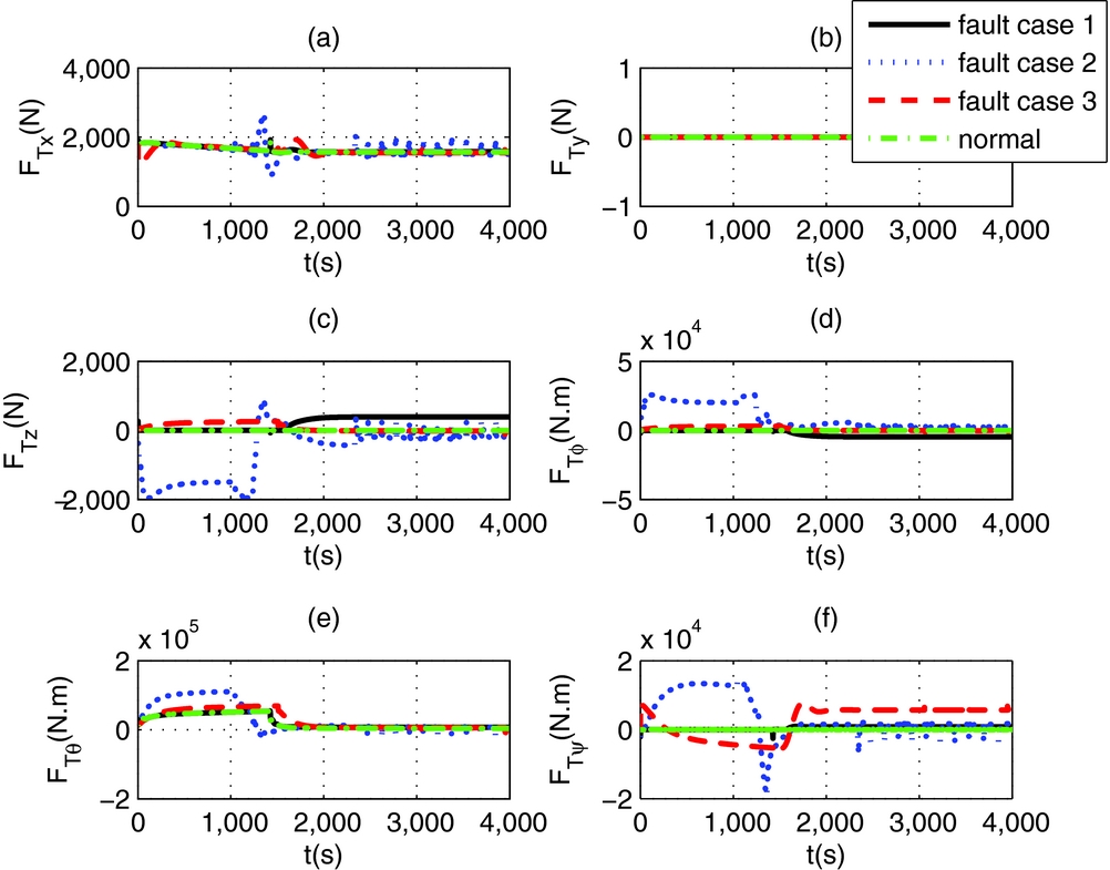
Position-tracking results in the normal case (in Fig. 9) compared with that in failure cases (in Fig. 21), there are not much differences in tracking processes. In the first failure case, propeller 3 is stuck at μ30= -60o and with a thrust deficiency of 1/2, so it is easy to reach its saturation position as shown in Fig. 24(e); the same situation also occurred in the second failure case in Fig. 29(e). The actuators are automatically allocated to compensate the deficiency of other actuators, for example, in Fig. 22(a), the rudder has opposite outputs in the second and third failure cases to adapt the different fault situations of propellers.
Trace-tracking results in the normal case (in Fig. 13) are compared with those in the failure cases (in Fig. 26). The final tracking results are similar, however with different actuator allocation results: for example, in the first failure case, propellers 1 and 5 are used for pitch control. Because of thrust deficiency, their pitch ability decreased, however, the elevator is used to compensate the pitch moment, as shown in Fig. 27(b); in the second failure case, the output of propeller 2 is very small (Fig. 29(c)). because it is stuck at 90o position. Its output is a disturbance for planar motion, so it should be suppressed; such the thrust output of propeller 5 is small too, because of the symmetric installation of propellers 2 and 5 (in Fig. 29(d)).
Altitude-tracking results in normal case (in Fig. 17) are compared with those in failure cases (in Fig. 30). In the second failure case, the fault propellers 1 and 5 are stuck at a certain angle, thus causing yaw disturbance. As a result, the rudder deflects at a certain angle (in Fig. 32(a)) in order to resist the yaw deviation, as shown in Fig. 31(b); and propeller 2 is stuck at 90°, so it reaches the maximum position to assist altitude control directly as shown in Fig. 34(c). For the third failure case, propellers 4 and 6 have totally failed, so only propeller 5 is used to balance the yaw moment, as shown in Fig. 34(d).
4.2.2 Control force allocation of multi-propellers
With respect to the control force allocation of the propellers, it can be seen from Figs 25, 30 and 35, that in case of fault situations, the actuator allocation strategy tends to relocate the actuators to achieve the same control forces as in the normal situation shown in Figs 25(a) and 30(a) for forward force and in Fig. 35(e) for pitch moment.
In plenary motion of position control and trace tracking, there are some pitch and roll moments generated because of the asymmetric drive of fault propellers, so the roll and pitch disturbance moments occurred (in Fig. 25(d, e) and Fig. 30(d, e)), also because of the fault propeller 3 is stuck at -60o, there is altitude disturbance, so extra vertical force is generated (in Figs 25(c) and 30(c)).
For vertical motion of altitude control, in failure case 2, the stuck propeller 2 generated vertical force to assist altitude control as shown in Fig. 35(c), and there are coupling roll moment and yaw moment generated due to the asymmetrical drive of fault propellers (in Fig. 35(d, f)).
5.0 CONCLUSION
The composite control system of hybrid-heterogeneous actuators is designed for an airship. It includes guidance strategy, basic controller design, moment allocation and reconfigurable actuator allocation. The novelty in the design of this control system are: (1) The indirect control force is introduced in the propeller model to guarantee existence of pseudo-inverse of the control coefficient matrix, thus this controller always has analytic solution, so it is easy to implement; (2) Three diagonal weight matrices are combined together to represent the all possible faults of vectored propeller, so this controller can be used on general situation. Using the mid-altitude airship as an example, the simulations of different control tasks are provided. The composite controller achieves a good distribution and reconfiguration among these heterogeneous actuators in case of failure, thereby enhancing the reliability of the control system.
ACKNOWLEDGEMENTS
This work was supported by National Science Foundation of China, no. 61733017 and no. 61175074.