1. INTRODUCTION
Although the Global Positioning System (GPS) has become nearly ubiquitous in positioning and navigation applications, the limited number of satellites means that locations with restricted satellite visibility, such as urban canyons and forested areas, have problems acquiring and tracking a sufficient number of satellites to compute a position. An effective means of minimizing this is to use other global navigation satellite system (GNSS) data to augment the GPS-only solution. To this end, the European Galileo and the Chinese Compass systems will certainly be useful, but these are not expected to be fully operational until beyond 2013 and 2015, respectively (Gibbons, 2008; Gibbons, 2009). In contrast, the Russian GLONASS system is currently being replenished and is nearly fully populated (20 satellites in operation at time of writing) and therefore offers excellent short- and long-term opportunities. Previous studies have shown that using GLONASS in addition to GPS provides very significant advantages such as increased satellite visibility and correspondingly better positioning accuracies (e.g., Lachapelle et al, Reference Lachapelle, Ryan, Petovello and Stephen1997; Ryan et al, Reference Ryan, Petovello and Lachapelle1998). Moreover, satellite observability aside, GNSS signals in general suffer significant errors due to the ionosphere. In these situations, dual-frequency measurements can be used to remove the first order effects, thus resulting in improved positioning accuracy (Misra & Enge, Reference Misra and Enge2001).
With this in mind, software receivers offer the power and flexibility to quickly utilize new signals and systems without the need for major hardware modifications. Given a suitable front-end, new frequencies and ranging codes can be used simply by making software changes (Ledvina et al, Reference Ledvina, Psiaki, Humphreys, Powel and Kintner2006). As such, a great flexibility can be achieved by using a software receiver (Bao & Tsui, Reference Bao and Tsui2000). Considerable effort has been directed to software based receivers in recent years and their popularity is expected to grow with some companies already offering commercial products (e.g. IFEN, 2007, Morton, Reference Morton2007, NXP, 2007, Scott, Reference Scott2007, CSR, 2008, Fastrax, 2008). Despite this, however, little work has been dedicated to GLONASS-capable software receivers. Furthermore, to the authors' knowledge, a pure software (i.e., no hardware-based processing) dual-frequency GLONASS receiver has not yet been implemented.
This paper presents a multichannel dual-frequency GLONASS software receiver that works in parallel with the GPS L1 C/A signals. The major contributions of this work are three-fold. First, it illustrates the key steps to implementing a dual-frequency GLONASS software receiver and demonstrates its capabilities. Second, it clearly outlines the algorithms that differ considerably relative to GPS and other systems. Finally, it compares the standalone pseudorange-based position accuracy using various combinations of the L1 and L2 GLONASS signals as well as the GPS L1 C/A signal.
Given the above, the primary objective of this paper is to present the methods used for acquisition, tracking and navigation data demodulation of GLONASS civilian L1 and L2 signals. For brevity, this presentation focuses on the key differences between GLONASS and GPS, with the understanding that many references on the latter are available in the literature (e.g., Van Dierendonck, Reference Van Dierendonck1995; Misra & Enge, Reference Misra and Enge2001; Tsui, 2005; Ward et al, Reference Ward, Betz and Hegarty2006). Moreover, dual-frequency ionosphere error mitigation is implemented and the positioning results are presented.
The paper begins with a brief overview of GLONASS including its signal structure and key differences relative to GPS. The software receiver is then introduced, and implementation details related to the GLONASS signals (especially relative to GPS) are highlighted. The results of two data collections are presented and analysed before relevant conclusions are drawn.
2. OVERVIEW OF GLONASS
2.1. Background
Similar to GPS, GLONASS is designed to provide an unlimited number of users with all-weather three-dimensional position, velocity and timing information anywhere in the world or near-Earth space (GLONASS ICD 2002). As part of a GLONASS modernization process, the second generation of GLONASS satellites, GLONASS-M, were designed and are still being launched. These new satellites broadcast a new civil L2 signal as well as additional navigation data that improve the performance of GLONASS significantly (Zinoviev, Reference Zinoviev2005). Having the second civil signal is very useful because of its ability, in conjunction with the L1 signal, to mitigate ionosphere error. Moreover, interference that affects L1 is not likely to affect L2 as well, thus providing additional interference mitigation. In total, the accuracy of GLONASS-M navigation signal is 2–2·5 times better than the original GLONASS navigation signal (Bartenev et al, Reference Bartenev, Kosenko, Zvonar and Chebotaryov2005). The launch of the first third-generation satellites, GLONASS-K, will begin in 2010. Along with the extended life-time of 12 years, GLONASS-K will be capable of broadcasting L3 civil signals, on which integrity information for the safety-of-life applications will be available (Zinoviev, Reference Zinoviev2005).
2.2. Current status
At the time of writing, there are 20 GLONASS satellites in the constellation (Information-Analytical Centre, 2008). Among these, 19 are GLONASS-M type satellites and it is expected that six more will be launched in 2009. Initially, system completion (i.e., a 24 satellite constellation) was planned by the year 2012, but more recent reports suggest the system may be fully deployed by the end of 2009 (Petrovski et al, Reference Petrovski, Engelsberg and Babakov2008).
2.3. GLONASS signal structure
Generally, any GNSS signal can be presented by the following equation:

where S(t) represents the signal received at the antenna, A is the amplitude of the received signal, C(t) is the ranging code, D(t) represents the navigation data message, f R is the frequency of the received carrier signal (including Doppler shifts), and φ is the initial phase of the carrier signal. Below, the key elements of the GLONASS signals relative to GPS and other GNSS are discussed.
2.3.1. Multiple access structure
Unlike all other current and planned GNSS, GLONASS satellites currently transmit the same ranging code signal on different frequencies using a Frequency Division Multiple Access (FDMA) technique. The impact of this approach on the software receiver implementation will be discussed below. For now, we instead focus on the interface between space segment and user equipment, which consists of two sub-bands of L-band, referred to as L1 and L2, with frequencies defined by the following expression (GLONASS ICD 2002):

Where i∊{1,2} represents the frequency band (1 for L1 and 2 for L2), f 0,i is the base frequency defined to be 1602 MHz for L1 and 1246 MHz for L2, K is the satellite's frequency number, and Δf i is the frequency spacing defined to be 562·5 kHz for L1 and 437·5 kHz for L2. The range of frequency numbers is specified in the GLONASS ICD (2002), but is currently planned to be in the range of −7 to +6 beyond 2005.
2.3.2. Ranging code
GLONASS satellites provide two types of ranging codes: standard accuracy and high accuracy. The standard accuracy code is designed for use by civil users worldwide. (GLONASS ICD, 2002). The GLONASS standard accuracy ranging code characteristics are shown in Table 1 (Beser & Danaher, Reference Beser and Danaher1993). Note that herein that the term “ranging code” is used in place of “standard accuracy ranging code”. The high accuracy ranging code is not considered in this work, as it is intended for military use. That said the techniques discussed in this paper would be applicable to this code as well with the appropriate changes.
GLONASS standard accuracy ranging code characteristics.

2.3.3. Signal power
For GLONASS satellites above an elevation 5°, as viewed from the receiver, the received power level of the L1 signal at the output of a 3 dBi linearly polarized antenna is specified not less than −161 dBW. For L2, the corresponding minimum power level is −167 dBW (GLONASS ICD, 2002). As such, the nominal power of the L2 signal is expected to be 6 dB lower than on L1, which will have an impact on acquisition and tracking. Specifically, acquisition and tracking of the L1 signal will not ensure acquisition and tracking of the L2 signal from the same satellite.
2.3.4. GLONASS navigation message
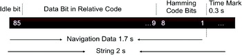
The transmitted navigation message includes immediate and non-immediate data transmitted at 50 bits per second. The GLONASS navigation message is generated as continuously repeating super-frames. A super-frame consists of five 30-second long frames, thus making the super-frame 2·5 minutes long. In turn, each frame consists of 15 strings, each with duration of 2 seconds. Each string contains data bits and time mark information. The time mark is equivalent to the preamble in the GPS message. The data bits occupy 1·7 seconds and the time mark has duration of 0·3 seconds. During the first 1·7 seconds within each string, 85 data bits are transmitted (original data bits have bit positions 9…84 and check bits are in positions 1…8). The data of each string is separated from the data of adjacent strings by the time mark (GLONASS ICD, 2002). Figure 1 shows a general view of a string structure.
String structure (from GLONASS ICD 2002).

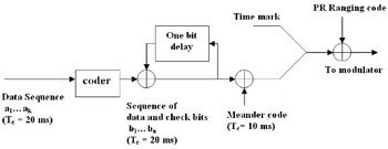
In addition to having a different macro-level structure from the GPS navigation message, the GLONASS navigation bit encoding is also different. The “original” GLONASS navigation data bits are each 20 ms long. A sequence of check bits (namely Hamming code bits) is included for verification. Up to this point, this structure is similar to the GPS navigation message. The navigation and check bits are then transformed into a “relative code” using a one-bit delay and modulo-2 addition of each bit with the previous one as shown in Figure 2. Then a 100 Hz meander code is modulo-2 added to the data bits. Because of the effect of meander code, the data bit duration is now effectively only 10 ms. The time mark bits, which are each 10 ms long, are then appended to the data bits. The combination of the data bits (modified as just described) and the time mark bits produce one two-second long string. The string is sent to the modulator for modulation with the ranging code. Figure 2 shows a block diagram of GLONASS data sequence generation. The impact of these differences (relative to GPS) in terms of receiver implementation will be discussed in the following sections.
GLONASS data sequence generation (from GLONASS ICD 2002).

3. SOFTWARE RECEIVER METHODOLOGY
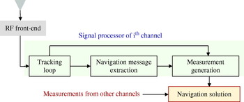
The final goal of any GNSS receiver is to generate a navigation solution. To achieve this goal, it is necessary that the received signals from the antenna be acquired and tracked. When tracking is complete, useful information is extracted and can be used to generate measurements, which in turn are used to compute a position. Figure 3 shows an overview of a general GNSS receiver. The received signals from the antenna are passed to the RF front-end where they are down-converted to the desired intermediate frequency and are sampled at the desired sampling rate. This process is generally different for each frequency band of interest. Samples are then sent to each tracking channel in parallel. Each tracking channel consists of tracking loops, navigation message extraction and a measurement generation block. Finally, measurements from all channels whose satellites are above a minimum elevation angle are used to compute the navigation solution.
GNSS software receiver overview.

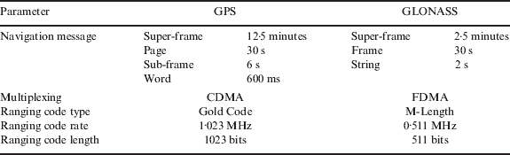
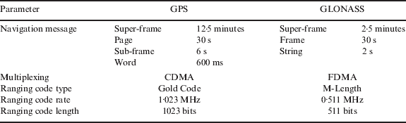
For a GLONASS software receiver, the acquisition and tracking processes are conceptually similar to those for a GPS software receiver. There are, however, a few major differences which must be considered. These are mostly related to the method of multiplexing and the ranging code used in the GLONASS system. Furthermore, as shown above, the GLONASS navigation message is completely different from that in GPS and therefore needs a different method for demodulation. Table 2 summarizes the key differences between GPS and GLONASS. The details regarding GNSS receiver implementation are not presented here. Rather, focus is given to the differences relative to the GPS case. For more details, interested readers are referred to the many references on GNSS receiver implementation that are available in the literature (e.g., Van Dierendonck Reference Van Dierendonck1995; Misra & Enge Reference Misra and Enge2001; Tsui 2005; Ward et al Reference Ward, Betz and Hegarty2006; Borre et al, Reference Borre, Akos, Bertelsen, Rinder and Jenson2007).
Summary of key differences between GPS and GLONASS.
3.1. Effect of ranging code
The GLONASS ranging code is different from the GPS ranging code. Specifically, unlike the GPS ranging codes which belong to the Gold code family, the GLONASS ranging code is a maximum length 9-stage shift register sequence. Therefore, for GLONASS signal acquisition and tracking, one and only one ranging code must be generated for all the GLONASS satellites as a replica ranging code. This offers memory savings for software receivers that pre-compute and store the ranging code at receiver start-up.
3.2. Effect of FDMA
The FDMA multiplexing used in GLONASS means that each satellite transmits its own carrier frequency. To handle this, the satellite whose frequency number is zero (i.e., f 0,i) is shifted to an intermediate frequency, f IF, in the front-end. Correspondingly, the other satellites' signals are offset relative to the IF by KΔf 1 and KΔf 2 for L1 and L2 respectively; see equation (2). Within the receiver, the local signals must then generate each satellites' frequency according to the following equation:

where f Doppler is the Doppler shift induced by relative motion between the receiver and the satellite. With the exception of the KΔf i term, equation (3) is exactly the same as is required for GPS. However, there is an important practical difference in terms of implementation in a software receiver. This revolves around the fact that the generation of the local signals is computationally very intensive. This is especially true for the carrier portion of the signal because of the evaluation of the transcendental functions (i.e., sin and cos). To reduce the processing requirements, a table of local phase values (actually sin and cos of the phase angles) is often generated ahead of time for one or more frequencies in the range of interest (e.g., Ledvina et al, Reference Ledvina, Psiaki, Humphreys, Powel and Kintner2004; Petovello & Lachapelle, Reference Petovello and Lachapelle2008). Once the table is created, it can be accessed much more quickly than computing the values on the fly, thus resulting in significant processing gains. Unfortunately, these approaches are not practical for GLONASS signals. The table method presented by Ledvina et al (Reference Ledvina, Psiaki, Humphreys, Powel and Kintner2004) would require an unreasonable amount of memory because the table would have to cover the full range of GLONASS frequencies (i.e., full range of 7·3 MHz at L1 for the range of frequency numbers to be used beyond 2005) instead of just the range of typical Doppler frequencies (typically ±5 kHz). Similarly, the method proposed in Petovello and Lachapelle (Reference Petovello and Lachapelle2008) would no longer be of any benefit because of the very large range of frequencies. Given the above, the only practical option is to generate the local signal on the fly, at the cost of increased processing time. As an extension, it is likely that some form of co-processor (e.g., FPGA, DSP, GPU) would be required to manage this in a real-time receiver.
3.3. Navigation message demodulation
The GLONASS navigation message contains information related to the satellite being tracked and also information related to the GLONASS constellation as a whole. As such, the navigation message must be decoded to extract this information which is necessary for computing the navigation solution and to aid other receiver operations. To this end, three steps are required, namely bit synchronization, string synchronization and navigation message decoding.
The method used for GLONASS bit synchronization is the histogram method presented in Van Deirendonck (1996) with the only difference being the time between data bit transitions (i.e., 20 ms for GPS and 10 ms for GLONASS).
The next step after bit synchronization is to find the location of the string within the received GLONASS signal. This is analogous to the frame synchronization process in GPS. For this purpose, the time mark pattern and its complement are searched. The complement must be searched because of the uncertainty in the polarity of the locally generated carrier signal. If the complement of the time mark is found, all previous and subsequent navigation data bits must be complemented as well (if it is confirmed that the complement has been found, the local carrier can be shifted by half a cycle in order to receive the signal with the proper navigation data bit polarity). After finding the time mark pattern or its complement, the received data is checked two seconds later to make sure it repeats (it should repeat every string, or every 2 s). After finding the location of the time mark, the data bits are converted from 10 ms data into 20 ms data bits by removing the effect of the 100 Hz meander sequence. In this step, data bit pairs are converted into one bit (the reverse process of adding the meander sequence to the data bits). After having removed the meander code, it is still necessary to transform from the relative code to get the original data bits. This is done by adding each bit to the previous one by modulo-2 addition. Finally, this reveals the original data bits (i.e., bits 9 to 84) which are then verified using the checking bits (i.e., bits 1 to 8 as seen in Figure 1). The algorithm for data verification allows the correction of an error in one bit within a string and detection (but not correction) of an error in two or more bits within a string. This algorithm is explained in detail in GLONASS ICD (2002) . When the data verification is passed, the correct navigation data bits are revealed and information can be extracted.
4. GLONASS L1 AND L2 ACQUISITION AND TRACKING
The acquisition method used for GLONASS L1 and L2 is similar to GPS with the exception of the key differences noted above. In case of carrier wipe-off, frequencies over a range of ±5 kHz around the carrier frequency are searched. The carrier frequency is calculated according to equation (3). For the code wipe-off, a Fast Fourier Transform (FFT) method was used (Bao and Tsui, Reference Bao and Tsui2000). For this purpose, one ranging code is generated as the replica code for all the received GLONASS signals.
Signal tracking is also similar to GPS. The phase discriminator implemented in the software for tracking is the two quadrant arctangent. The discriminator is chosen from the various Costas discriminators (Ward et al, Reference Ward, Betz and Hegarty2006) to be insensitive to the effect of navigation data bit transitions. The selected frequency discriminator selected is the decision-directed type. For the code discriminator, the non-coherent early minus late envelope type is used (Ward et al, Reference Ward, Betz and Hegarty2006). The phase lock loop (PLL) and delay lock loop (DLL) were selected to have second order loop filters and therefore are insensitive to range rate but produce an error in the presence of range acceleration. However, this will not be significant for the static data analyzed herein. The frequency lock loop (FLL) uses a first order loop filter. Table 3 summarizes the tracking loop parameters used in the software.
Tracking loop parameters used in software receiver.

4.1. Software implementation
The GLONASS signal acquisition and tracking was implemented in a modified version of the Position, Location And Navigation (PLAN) group's software receiver, GSNRx™ – GNSS Software Navigation Receiver (Petovello et al, Reference Petovello, O'Driscoll, Lachapelle, Borio and Murtaza2008). The GSNRx™ software was initially developed for acquiring and tracking the GPS L1 C/A signal and is capable of processing the raw samples from the RF front-end and generating measurements to be used in other data processing programs. The software also computes a navigation solution internally. By implementing the changes listed above, the GSNRx™ software was successfully modified to track the GLONASS L1 and L2 signals and to extract the GLONASS navigation message data. The following section presents the results of data analysis.
5. RESULTS AND DATA ANALYSIS
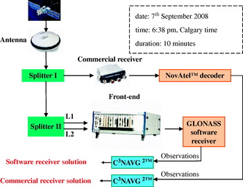
To validate the GLONASS software receiver, an experiment was set up on 7 September 2008. The data collection was conducted for ten minutes starting at 6:38 pm local time under open-sky conditions on the roof of a building at the University of Calgary, Alberta, Canada. The block diagram of this experiment is shown in Figure 4. In this experiment, the GLONASS software receiver was compared with a commercial hardware receiver. The commercial receiver used for this purpose was a NovAtel™ OEMV-2 receiver. The received signal from the antenna was sent to the splitter (splitter I). One of the signals from the splitter was sent to the NovAtel™ receiver which was configured to log the raw measurement data. The other signal from the splitter was sent to yet another splitter (splitter II). The outputs of the second splitter are defined as L1 and L2 and sent to different RF inputs on the front-end. The samples from the front-ends were then input into GSNRx™ for processing.
Experiment set up to verify GLONASS software receiver.

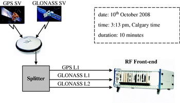
Both the NovAtel™ data (after decoding to the proper format) and the data from the GSNRx™ software receiver were then fed into a software package called C3NAVG2™. This software was developed in the Position, Location And Navigation (PLAN) group at the University of Calgary. C3NAVG2™ is a C program that processes GPS and/or GLONASS pseudorange data in both static and kinematic modes. One of the outputs of this software is the position of the antenna at each epoch. Processing both the NovAtel™ and GSNRx™ data with the same software allows for a fair and direct comparison between the two receivers. Following the initial validation of the GLONASS data processing in GSNRx™ using the above test (results and analysis to follow), a second test was conducted to validate the GLONASS software receiver in combination with GPS. In this experiment GPS L1 signal was collected along with GLONASS L1 and L2 signals as illustrated in Figure 5. The data collection was conducted for ten minutes on 10 October 2008 starting at 3:13 pm local time under open-sky conditions on the roof of a building at the University of Calgary, Alberta, Canada. The antenna used is capable of receiving GPS and GLONASS L1 and L2 signals. The received signals were sent into a splitter where they were divided into three parts. These three signals were then sent to the three channels of an RF front-end for collecting GPS L1, GLONASS L1 and GLONASS L2 signals, respectively. The sampling rate was chosen to be 12·5 Msps for both GPS and GLONASS signals for both experiments.
Experiment set up to verify GPS+GLONASS software receiver.

5.1. Acquisition results
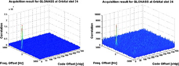
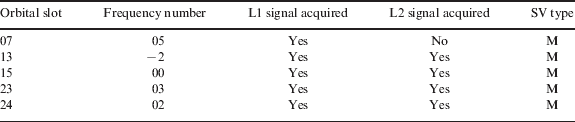
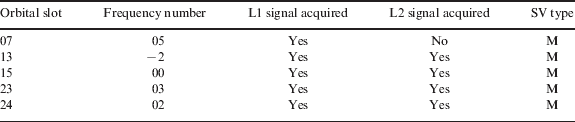
Table 4 shows the GLONASS L1 and L2 signals acquired. It is noted that the L2 signal of GLONASS satellite at orbital slot 07 was not acquired because this satellite had a low elevation and its L1 signal was weak. As discussed previously, the GLONASS L2 signal is nominally weaker than on L1 and as such could not be acquired. Some representative acquisition plots for the GLONASS L1 and L2 signals for orbit slot 24 are shown in Figure 6. Acquisition results for L1 and L2 show that the correlation peak is indeed lower for L2, as expected. Nevertheless, the correlation peaks are sufficiently strong to correctly identify the code phase and carrier frequency of the signal. Furthermore, it is clear that both the L1 and L2 signals have similar parameters, as expected (the relative ionospheric delay will be small given that the data was collected during solar minimum). As with GPS, the acquisition parameters obtained from the figures shown (and for other satellites) are used to initialize the tracking process, the results of which are discussed below.
Acquisition result for GLONASS L1 (left) and L2 (right) signals at orbital slot 24.

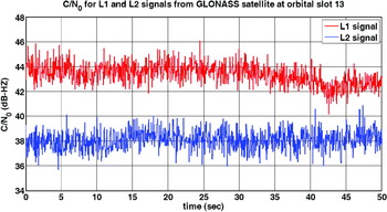
C/N0 for L1 and L2 signals from satellite at orbital slot 13.

Acquired GLONASS L1 and L2 signals.
5.2. Tracking results
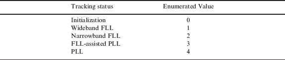
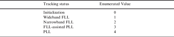
This section presents the signal tracking results for the GLONASS signals in terms of carrier to noise density ratio, frequency lock and phase lock. However, to facilitate analysis, the tracking status is also plotted. To this end, the tracking status is defined by the enumerated values shown in Table 5.
Tracking status in software.
5.2.1. Carrier to noise density ratio estimation (C/N0)
The carrier to noise density ratio estimation is performed using the power ratio method (PRM) described in Van Dierendonck (Reference Van Dierendonck1995) . Table 6 summarizes the C/N0 values for the L1 and L2 signals being tracked. The values in the table represent average C/N0 values over 10 minutes. It is noted that, relative to Table 4, the satellite at orbital slot 07 has been removed because this satellite is at a low elevation and the L2 signal could not be acquired and tracked. Figure 7 plots the C/N0 value for the GLONASS L1 and L2 signals from the GLONASS satellite at orbital slot 13. The results show that the L2 C/N0 values are approximately 6 dB lower than at L1, as expected.
Average C/N0 values for L1 and L2 signals.

5.2.2. Frequency lock analysis
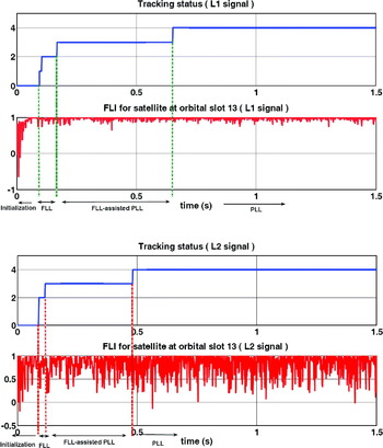
Having confirmed proper code tracking, the analysis now turns to assessing the carrier tracking performance of the receiver. Figure 8 plots the L1 and L2 frequency lock indicator (FLI) values, as computed in Mongredien et al (Reference Mongredien, Lachapelle and Cannon2006) . The FLI values take on a maximum value of unity when the frequency is perfectly tracked. As shown, during the initialization period, carrier loop tracking is performed using FLL alone. The initialization period allows the FLI values to converge before being used to decide to transition to later tracking stages including wideband FLL, narrowband FLL and FLL-assisted PLL. In FLL-assisted PLL mode, the value of phase lock indicator (PLI; discussed below) is also checked. It is seen that during initialization period, FLI for the L2 signal converges faster than L1. This arises because, in this case, the initial estimate of the carrier Doppler from the acquisition process was closer for L2 than for L1. As a result, the tracking loop is able to converge more quickly and the switching from FLL mode to PLL mode occurs more quickly.
FLI for GLONASS L1 (top) and L2 (bottom) signals transmitted from GLONASS satellite at orbital slot 13.

5.2.3. Phase lock analysis
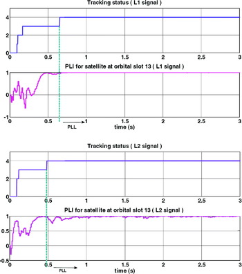
Figure 9 presents the phase lock indicator (PLI) value, as computed in Van Dierendonck (Reference Van Dierendonck1995) for the GLONASS L1 and L2 signals transmitted from the satellite in orbital slot 13. As with the FLI, a value of unity indicates perfect phase tracking. The PLI value is used to determine when the receiver should transition from FLL-assisted PLL to PLL. The PLI values are also used in PLL mode to determine when phase lock is lost, in which case the receiver returns to wideband FLL mode. Given that achieving PLL is the ideal objective of the tracking process (since it allows the carrier phase measurements to be used for high accuracy positioning applications), it is important that phase lock be re-established as quickly as possible following loss of lock. As shown in the figures, the PLI for L2 converges more rapidly. This is for the reasons discussed above. However, once PLL mode is reached, the L1 signal can be tracked better than L2, although both signals are tracked sufficiently well to be used for high accuracy applications.
PLI for GLONASS L1 (top) and L2 (bottom) signals transmitted from GLONASS satellite at orbital slot 13.

5.3. Navigation solution results
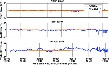
After GLONASS navigation message demodulation, the ephemeris data, as well as the observation data generated from the GLONASS software receiver, was processed using the University of Calgary's C3NAVG2™ software. Table 7 compares the root mean square L1-only GLONASS-only position error for measurements obtained from GSNRx™ and from the NovAtel™ receiver. The GSNRx™ solution is very similar to the NovAtel™ solution and at the level expected of a single point receiver. A part of their difference is related to the splitter (II) which attenuates the signal processed by GSNRx™ by an additional 3 dB. Other key differences between the receivers likely lie with the specific tracking loop parameters, most notably the correlator spacing (early-to-late spacing of one chip in GSNRx™ in this case).
Root Means Square (RMS) position errors for GSNRx™ and NovAtel™.

Figure 10 shows the position error as a function of time for the GSNRx™ and NovAtel™ solutions (both L1-only). The large error seen in the GSNRx™ solution at some epochs is related to the rejection of a weak GLONASS satellite in the C3NAVG2™ program. It is also noted that the NovAtel™ solution is much smoother than that from GSNRx™. Again, this is likely due to the fact that the NovAtel™ receiver uses narrower correlator spacing (relative to GSNRx™) and thus will inherently provide better multipath mitigation.
Position error comparison of GSNRx™ (L1) and NovAtel™ (L1).

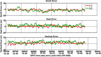
Having shown satisfactory L1-only results, the analysis now shifts to include L2 data. To this end, the position solution results for L1-only and L2-only from GSNRx™ are shown in Figure 11 and the RMS errors are summarized in Table 8. For these solutions, only the four satellites for which the L2 data is available are used (even for L1 solution) in order to avoid effects due to different satellite geometry. Results show that the RMS position errors for L1-only and L2-only solutions are approximately the same, which is expected given the calm ionospheric conditions present during the test. However, the L2-only results are slightly poorer, which is attributed to their lower received signal power.
Position error comparison of L1 and L2 computed using GSNRx™.

Root Means Square (RMS) position errors for L1 and L2 solution.

5.4. Ionosphere-free navigation solution results
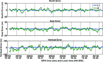
Using the approach presented in, for example, Misra & Enge (Reference Misra and Enge2001) for dual-frequency ionosphere removal, the ionosphere-free pseudorange (IF) was generated. The pseudorange data was then fed into C3NAVG2™ in order to compute an ionosphere-free navigation solutions. Figure 12 compares the positioning error from GLONASS L1 and GLONASS IF solutions. As can be seen, the IF results are actually slightly worse than the single frequency results, with the corresponding statistics summarized in Table 9. This is attributed to three factors:
• Forming of the IF measurement increases the effect of noise and multipath by a factor of about three (Misra & Enge, Reference Misra and Enge2001).
• The L2 data is not as accurate as the L1 data due to its lower received power.
• The inter-frequency biases between the different signals have not been accounted for, which will introduce a bias into the IF solution.
Despite this particular set of results, the ability to acquire and track dual-frequency GLONASS data is expected to become more important as we near the next solar maximum.
L1 and ionosphere-free positioning comparison.

Mean, RMS, and standard deviation of the positioning errors for L1 and IF solution.

5.5. GPS+GLONASS results
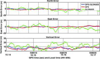
In this section, positioning results from the combined GPS/GLONASS software receiver are compared to those using GPS and GLONASS alone. The time series of errors for each solution are shown in Figure 13. These results are generated using the data set collected on 10 October 2008. As shown, the combination of GPS and GLONASS solution shows similar results to the GPS alone solution. This arises for two main reasons. First, there are more GPS satellites visible than GLONASS satellites (seven versus five). Second, the GPS measurement variances in C3NAVG2™ are smaller than the GLONASS variances because of their wider signal bandwidth and improved orbit models (i.e., satellite coordinate accuracies). As such, it is expected that the combined solution will closely approximate the GPS alone results.
Positioning error for GPS, GLONASS and GPS+GLONASS.

Table 10 shows the RMS position errors for the three solutions. According to the table, the north and east errors are smallest for the combined GPS and GLONASS solution. However, the GPS-only solution has the smallest height error. Overall, there is not much difference between the GPS alone and the GPS/GLONASS solution, as discussed above. It should be noted that these statistics are computed over only a few minutes (approximately three minutes) and could therefore exhibit short term biases that would be averaged out over longer periods. It is expected therefore, that the results would be different if longer data sets were considered (e.g., one day or more), where the short term variations in the measurement errors and satellite geometry are averaged out. Nevertheless, these results do show the benefit of GLONASS, even under relatively benign operating environments.
RMS value of the position error.

6. CONCLUSIONS
This paper described the implementation of a dual-frequency GLONASS software receiver that also works with GPS L1 C/A signals. After briefly reviewing the GLONASS signal structure and its differences relative to GPS, the necessary changes to a GPS software receiver were described. To this end, the largest practical difference relates to the generation of the local signals within the receiver which cannot take advantage of efficiency improvements developed in GPS-only receivers. The decoding of the navigation message is also different because of a different encoding strategy using in GLONASS. All of the necessary modifications needed to acquire and track GLONASS signals in post-mission were added to the University of Calgary's GSNRx™ software receiver and two sets of data were collected to evaluate the performance of the software receiver.
The first test was used to assess the GLONASS signal acquisition, tracking and navigation solution performance. In terms of signal acquisition and tracking, results showed that all signals in view could be acquired assuming their signals were sufficiently strong. In particular, the C/N0, FLI and PLI values were shown to give satisfactory results. The resulting L1-only navigation solution was found to be comparable to that of a commercial receiver and able to provide metre-level accuracy in single point mode. Comparing the L1-only and L2-only solutions from the software receiver showed a slight degradation of the L2 solution, which is attributed to the lower received power level on that signal. An ionosphere-free pseudorange measurement was also formed using the dual frequency data and was found to give a slightly worse position solution due to the increased effects of noise and multipath. Nevertheless, the ability to compute an ionosphere-free solution will be important as we near the next solar maximum.
The second data set was used to assess the relative performance of the GPS-only, GLONASS-only and GPS/GLONASS solutions. As expected, the dual-system solution provided the best overall results. It is noted however, that the differences relative to the GPS-only solution were relatively minor, owing to the higher number of GPS satellites available during the test and the higher weight given to the GPS data in the navigation solution software.
Overall, it is concluded that a GPS/GLONASS software receiver is indeed feasible and is beneficial for improving positioning performance. Moving forward, the developed software receiver will serve as a research tool for GPS/GLONASS integration. Furthermore, as some of the newer GLONASS-K satellites are launched, the software receiver will be able to be easily updated to acquire and track the new signals that will become available.