1. Introduction
Indoor corridor navigation for micro aerial vehicles (MAVs) in GPS-denied corridor environments is a challenging task. This paper presents a novel vanishing-point detection approach based on connected components and straight-line detection in the corridor image frames to compute the heading and position of the MAV. The position and heading of the MAV can be estimated using a 720-pixel forward camera mounted on the MAV. Many researchers have used camera-based navigation as an alternative approach for navigation of MAVs in GPS-denied environments. To successfully navigate inside the indoor environment, a MAV must be fully aware of its position and heading to make suitable decisions to follow a collision-free path. A visual simultaneous localisation and mapping (VSLAM) camera-pose estimation algorithm is used to localise and stabilise the MAV in an unknown and unstructured environment at a desired setpoint during simple flight manoeuvres such as take-off, hovering, setpoint following or landing (Blösch et al., Reference Blösch, Weiss, Scaramuzza and Siegwart2010). Using real-time sensor data, a monocular simultaneous localisation and mapping (SLAM) system has been used to navigate the MAV in GPS-denied environments (Urzua et al., Reference Urzua, Munguía and Grau2017). A grid-based vanishing-point detection method is used to estimate the lateral deviation and heading for navigation of the MAV in indoor corridors with an accuracy of ±5 cm and ±1⋅5°, respectively (Anbarasu and Anitha, Reference Anbarasu and Anitha2017). Perspective cues extracted from the corridor and staircase image frames are used to classify the type of indoor environment for autonomous MAV flight in indoor corridor and staircase environments (Bills et al., Reference Bills, Chen and Saxena2011). In underground mine environments, depth information and a convolutional neural network method is used to follow a collision-free path for vision-based MAV navigation (Mansouri et al., Reference Mansouri, Karvelis, Kanellakis, Kominiak and Nikolakopoulos2019). In indoor environments, an optical flow-balancing algorithm, laser pointer-based triangulation method and visual odometry system based on the extended Kalman filter (EKF) are used to estimate a collision-free path for forward obstacle avoidance and trajectory of the vehicle for MAV navigation and localisation (Agarwal et al., Reference Agarwal, Lazarus and Savvaris2012). Passive visual sensors with anti-interference ability can obtain information and perception of the surrounding dynamic indoor environments (Lu et al., Reference Lu, Xue, Xia and Zhang2018). In cluttered environments, vision-based path planning, dense mapping and global trajectory generations with narrow field-of-view sensors are used for MAV flight (Oleynikova et al., Reference Oleynikova, Lanegger, Taylor, Pantic, Millane, Siegwart and Nieto2020). The structure of the scene, position of the camera and attitude of the indoor vertical-take-off-and-landing (VTOL) MAV have been computed by processing the image feature point coordinates and extracting the inverse depths using the sparse bundle adjustment algorithm (Schlaile et al., Reference Schlaile, Meister, Frietsch, Keßler, Wendel and Trommer2009). In unknown environments, an autonomous 3D global occupancy mapping and vector field histogram+ (VFH+) algorithm is used to explore and navigate a quadrotor MAV (Fraundorfer et al., Reference Fraundorfer, Heng, Honegger, Lee, Meier, Tanskanen and Pollefeys2012). Visual markers, ground optical flow data and an inertial measurement unit (IMU) have been used to improve the MAV pose estimation and achieved the desired navigation performance in the conducted experimental flight trials (Pestana et al., Reference Pestana, Sanchez-Lopez, De la Puente, Carrio and Campoy2016). In urban corridor environments of varying widths, bio-inspired vision-based control strategies based on instantaneous optic flow patterns have been proposed for quadrotor navigation (Keshavan et al., Reference Keshavan, Gremillion, Alvarez-Escobar and Humbert2015). In unstructured outdoor environments, deep neural networks are used for obstacle detection and to estimate the lateral offset of the MAV (Smolyanskiy et al., Reference Smolyanskiy, Kamenev, Smith and Birchfield2017).
2. Related work
Recently, many approaches have been proposed for indoor navigation of MAVs. Image pixels with similar gradient orientations extract lines for vision-guided robot navigation (Kahn et al., Reference Kahn, Kitchen and Riseman1990). Several methods have been proposed to detect vanishing points based on the Hough transform algorithm and different parameter spaces. Vanishing points of three mutually orthogonal directions (one finite vanishing point, two infinite vanishing points) have been detected in the outdoor man-made environment (Rother, Reference Rother2002). Parallel straight lines in man-made scenes can be extracted using the Hough transform algorithm, and the vanishing point can be detected by using the intersection of parallel straight lines in real-scene image frames (Chen et al., Reference Chen, Jia, Ren and Zhang2010). An efficient vision algorithm has been proposed to compute the camera location and indoor unmanned aerial vehicle pose with respect to the coloured track based on vanishing geometry (Wang, Reference Wang2011). A straight line in the image frame is the projection of a straight line in the 3D world, and projections of parallel straight lines in the 2D image frames intersect at a point called the vanishing point (Ma et al., Reference Ma, Soatto, Košecká and Sastry2001). The Hough transform algorithm is used to detect straight lines in the image frames, but one of the main limitations is its computational complexity (Bailey et al., Reference Bailey, Chang and Le Moan2020). Vanishing points and vanishing directions estimated in structured man-made environments can be used for partial camera calibration to estimate the relative orientation of the camera with respect to the actual scene (Kosecka and Zhang, Reference Kosecka and Zhang2002). The vanishing point that represents the scene vertical direction is used to compute the height of straight objects (Andaló et al., Reference Andaló, Taubin and Goldenstein2015). A vanishing point detection algorithm based on a direct split-and-merge (DSaM) algorithm is better compared to the Hough transform algorithm for the detection and localisation of the vanishing point in the structured image frames (Gerogiannis et al., Reference Gerogiannis, Nikou and Likas2012). Simultaneous localisation, mapping algorithms and visual cues of the environment can be used to estimate the range and bearing of landmarks for navigation of the MAV in riverine environments (Yang et al., Reference Yang, Rao, Chung and Hutchinson2011). A Kalman filter tracks the vanishing point detected in the railway track image frames acquired using the frontal camera mounted on the augmented reality (AR) Drone unmanned aerial vehicle (UAV) (Páli et al., Reference Páli, Máthé, Tamás and Buşoniu2014). Different objects can be recognised in binary image frames using the connected-component labelling by assigning a unique label to object pixels (He et al., Reference He, Ren, Gao, Zhao, Yao and Chao2017). A data fusion method for magnetometer, accelerometer, gyroscope (MARG) and optical flow sensors is proposed to compute the 3D attitude estimation for UAVs (Liu et al., Reference Liu, Li, Shi, Xu and Tang2021). The Hough transform algorithm detects straight lines in a parameter space (Duda and Hart, Reference Duda and Hart1972). Hough transform and the k-means clustering algorithm is used for the detection of vanishing points in the corridor image frames (Ebrahimpour et al., Reference Ebrahimpour, Rasoolinezhad, Hajiabolhasani and Ebrahimi2012). Three dominant orthogonal vanishing directions are associated with the reference world coordinate frame and the detection of vanishing points, and vanishing lines in the three orthogonal directions are used to estimate the camera orientation with respect to the scene (Kosecka and Zhang, Reference Kosecka and Zhang2002).
The major contribution is the integration of the connected components algorithm and k-means clustering algorithm for vanishing point detection in the corridor image frames to estimate the heading of the MAV. With conventional methods, the Hough transform algorithm is used for straight line detection in the image frames. From the literature review, the computational complexity of the Hough transform algorithm is high for detecting straight lines. To overcome this limitation, the connected component algorithm is used in this work to detect more parallel straight lines in the corridor image frames with less computational complexity compared to the Hough transform algorithm. The combination of the connected component algorithm and the k-means clustering algorithm is proposed to detect the vanishing point in the image frames acquired from the frontal camera mounted on the AR Parrot Quadrotor Drone version two.
3. Proposed vision-based heading estimation method
A heading estimation for MAV navigation based on vanishing point detection in corridor image frames is proposed, as illustrated in Figure 1.
The block diagram of the proposed method

The main contribution is the integration of the connected components algorithm and k-means clustering algorithm in the greyscale channel colour space to estimate the heading and position of the MAV with respect to the corridor image frames with five different image resolutions: 256 × 256 pixels, 240 × 320 pixels, 480 × 640 pixels, 960 × 1280 pixels, and 512 × 512 pixels.
The RGB corridor image was transformed to a greyscale channel during the image preprocessing step, and the corridor image's contrast was enhanced by varying the intensity levels. The contrast-enhanced corridor image frames were subjected to histogram equalisation in order to achieve 64-bin image equalisation. Before determining which pixels in the corridor image frame are the edges, a 45° convolution kernel was employed. Using the canny edge detection method, strong edge pixels were identified in the greyscale channel corridor image frame using the canny edge detection method. Using the connected components algorithm, straight lines with a 45° orientation were found in the greyscale channel corridor image frame. Using the k-means clustering algorithm, a vanishing point was identified in the greyscale channel corridor image frame.
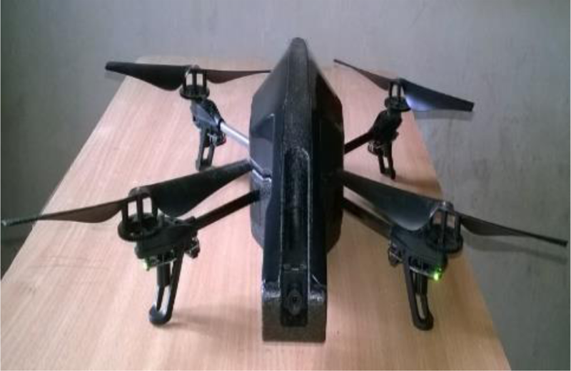
The direction of the MAV in a GPS-denied corridor environment has been computed using the Euclidean distance between the corridor picture centre and mid-pixel coordinates at the final row of the image and the detected vanishing point pixel coordinates in the subsequent corridor image frames. Lastly, if the MAV deviates from the centre, a control signal based on the heading measurement can be sent to the flight controller of the MAV to align it at the centre of the corridor. The videos of the corridor image frames are acquired and transmitted by a forward camera with a video capture resolution of 720 pixels mounted on an AR Parrot Quadrotor Drone version two (see Figure 2) directly to the smartphone at a frame rate of 30 fps by establishing a connection with a wi-fi network. The AR Parrot Drone is used in this research work to acquire real-time videos of the corridor environment. The actual value of the yaw measurements was obtained from the inertial measurement unit (IMU) mounted on the drone over a wi-fi connection to the ground station.
Parrot AR drone quadrotor version 2.0
3.1 Image frame preprocessing
The acquired corridor videos are converted into image frames. Each corridor image frames with an image resolution of 3240 × 4320 pixels from video are resized into five different image resolutions (256 × 256, 240 × 320, 480 × 640, 960 × 1280 and 512 × 512 pixels) to minimise the processing time. The RGB image frame is converted into greyscale to retain and remove the luminance, hue and saturation information. Greyscale image intensity values are adjusted to increase the contrast of the image. Next, an histogram equalisation is employed to enhance the contrast of the intensity-adjusted greyscale image. Finally, a 45° convolution kernel is applied on the contrast-enhanced greyscale image to extract the 45° edges or parallel line in the corridor environment. Figure 3 shows the image preprocessing output.
Image preprocessing output in a corridor image: (a) input image, (b) adjusted greyscale image intensity output image, (c) histogram equalised image output and (d) 45° edges detected

3.2 Canny edge detection method
The canny edge detection method used a Gaussian filter to filter out any noise from the contrast-enhanced greyscale image. To compute the image intensity gradient, a pair of convolution masks was applied to the filtered contrast-enhanced greyscale image. To highlight the image regions with high spatial derivatives, the gradient strength and direction were computed. Non-maximum suppression was applied to remove unwanted edge pixels by checking a pixel in its local neighbourhood in the gradient direction. Upper and lower threshold values were used to determine the weak- and strong-edges pixels. Finally, strong-edge pixels were detected in the corridor image frames by removing all the weak-edge pixels below the lower threshold. Figure 4 shows the edges detected in the corridor image.
Edge detection output in a corridor image: (a) input image and (b) edges detected using the canny method

3.3 Straight lines detection using connected component algorithm
Common gradient-oriented image neighbouring-edge pixels detected using the canny edge detection method was used in the connected component analysis to produce a connected image contour or candidate line $\ell$ . In the line fitting stage, line feature candidates were obtained by fitting straight lines to the connected component segments extracted from the connected component analysis. A line support region was produced based on the list of connected component edge pixels $\{ ({x_i},{y_i})\} _{i\textrm{ = }1}^n$
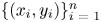 , which were connected and grouped based on their gradient orientation.
From the matrix (D) associated with the line support region, eigenvalues λ 1, λ 2 and eigenvectors v 1, v 2 of the matrix (D) were calculated to compute the line parameters as follows:

where $\tilde{x}\textrm{ = }{x_i} - \bar{x}$ and $\tilde{y}\textrm{ = }{y_i} - \bar{y}$
 denotes the mean corrected image pixel coordinates of every pixel $(x{}_i,y{}_i)$
 in the connected component, and $\bar{x}\textrm{ = (1/}n\textrm{)}\sum\nolimits_i {{x_i}}$
 and $\bar{y}\textrm{ = (}1\textrm{/}n)\sum\nolimits_i {{y_i}}$
 are the means.
Eigenvalues should be zero for an ideal line, and the line fit quality is characterised by the ratio between two eigenvalues ${\lambda _1}\textrm{/}{\lambda _2}$ (with λ1 > λ2) of D.
On the 2D image plane, point (x,y) must satisfy the following equation

Geometrically, $\theta$ denotes the angle between the line $\ell$
 and the $x$
 -axis, and $\rho$
 denotes the distance from the origin to the line $\ell$
 . The line parameters ($\rho ,\theta$
 ) are computed from the calculated eigenvectors v 1, v 2, where v 1 denotes the eigenvector associated with the largest eigenvalue. The line parameters are calculated by using the following equations:


where ($\bar{x},\bar{y}$ ) denotes the midpoint of the line segment. A connected component algorithm extracted the lines in the corridor image frames from the detected edges. Figure 5 shows the line detection output using the connected component algorithm.
Line detection output in a corridor image: (a) input image and (b) detected lines

3.4 K-means clustering-based vanishing point detection method
If the corridor areas have been modelled with more line densities, the corridor shape and the gap between the corridor walls on the left and right sides can be easily distinguishable in the corridor image frames by using the k-means clustering algorithm. Using the k-means clustering method, the left and right clusters can be extracted, representing the left and right corridor walls, respectively, and the space between the left and right clusters could be used for MAV navigation without colliding with the walls. For each assigned observation, the k-means clustering method will return the cluster index by partitioning the data into k mutually exclusive clusters (k = 4). Each line's starting and ending pixels have been used as a set of data applied as input to the k-means clustering method. The line dataset contains the starting and ending pixel of each line detected in the corridor image frames. The processing time of the k-means clustering method has been reduced by considering only the starting and ending pixels of the detected lines. Line datasets have been classified into four clusters. For final clustering, the centroid of each extracted cluster is used to form a final set of data. The location of the final centroid has been considered as the final location of the vanishing point. The MAV can navigate in corridor environments in the available space between the extracted clusters.
The k-means cluster centroids in space have been randomly initialised for the k-means algorithm:

Assign each data point's closest cluster centroids to its respective spatial location. The following is the Euclidean distance in d-dimensional space between the centroid and data point zp:

Once again, locate the cluster centroids using the centroid definition. As a result, the following is the location of cluster j's centroid:

where Cj is the subset of data points that are part of cluster j, and nj is the total number of data points in this cluster. The final clustering dataset is derived from each cluster's centroid. The centroid's ultimate location can be found by using the k-means clustering approach on the final clustering dataset. It has been suggested that this centroid final location is the vanishing point final location.
Only the beginning and end line pixels of the detected straight lines were applied to the k-means algorithm to extract the two left and two right clusters based on the value of k in the corridor image frames. This was done to ensure that the k-means clustering algorithm in actual flight is convergent. At least four cluster centroid must be estimated to determine the final centroid's precise location. To estimate the final centroid, which indicates the precise location of the vanishing point, an ideal value of k equal to 4 is used. Figure 6 shows the vanishing point detection based on the k-means clustering method.
K-means clustering and vanishing-point detection output in a corridor image: (a) input image, (b) k-means clustering of detected starting and ending of line pixels, (c) detected cluster centroids and (d) the final clustering result is the detected vanishing point

A vanishing point with pixel coordinates of (186⋅9235, 154⋅5304) is detected after final clustering using the k-means clustering method in the corridor image when the MAV is heading from centre of the corridor to the right of the corridor by 20°.
3.5 Heading estimation using vanishing point coordinates
Vanishing point coordinates estimated using the connected-component algorithm and k-means clustering method are used for the MAV heading estimation in the corridor environment.
The yaw angle or heading (Ψ) angle of a MAV in a corridor environment towards the left or right from the corridor centre can be computed as

where D represents the horizontal Euclidean distance measure between the image centre and the detected vanishing point coordinate in the successive corridor image frames, and V represents the vertical Euclidean distance measure between the centre of the image frame to the central pixel at the last row of the image frame.
The above equation can be used to calculate the MAV heading from the centre of the corridor to the right of the corridor by 20°. The calculated heading value is 20⋅04°.
3.6 Root-mean-squared error (RMSE) and mean absolute error (MAE) estimation
The heading measurement results are evaluated using root-mean-squared error (RMSE) and mean absolute error (MAE) metrics. These metrics are computed using the following equations:


where ${\hat{y}_i}$ denotes the measured value for a determined time t, ${y_i}$
 denotes the actual value for that same time and N is the total number of heading measurement observations.
4. Results and discussions
An efficient and robust algorithm is developed in a MATLAB environment for the estimation of a vanishing point based on a connected component algorithm and k-means clustering method. The detected vanishing point can be used for determining the MAV position (centre, left or right of the corridor) and heading of the MAV in a corridor. The computed navigation parameters can be used for indoor navigation of the MAV in a GPS-denied corridor environment. When the estimated heading is to the left or right by a few degrees using vanishing point coordinates, for collision-free navigation, the MAV should align with the centre of the corridor. Real-time video has been acquired at a frame rate of 30 fps by using the high-definition 720-pixel frontal camera. The MAV flying position in the centre, left and right of the corridor can be determined based on the position of the detected vanishing point. This is shown in Figure 7.
MAV position in a corridor environment: (a) corridor left, (b) corridor centre and (c) corridor right

Corridor video is converted into image frames with an image resolution of 3,240 × 4,320 pixels. The proposed vanishing point detection method performs well in the position and heading estimation for corridor image frames captured during daytime and nighttime. The position of the detected vanishing point in the image indicates the actual location of the MAV in the corridor environment. To illustrate that the proposed algorithm is suitable for different image resolutions and to reduce the processing time, in this work five different image resolutions (256 × 256 pixels, 240 × 320 pixels, 480 × 640 pixels, 960 × 1280 pixels and 512 × 512 pixels) have been used for the heading and position estimation. Geometry between the centre of the image pixel coordinates, detected vanishing point pixel coordinates in the successive corridor image frames and the central pixel coordinates at the last row of the image is used to compute the heading of the MAV towards the left or right from the centre of the corridor.
The MAV can compute its position and attitude (yaw angle) based on the detection of a vanishing point using the proposed integrated connected-components algorithm and k-means clustering algorithm in the greyscale channel colour space. The development of the proposed algorithm enables the MAV to recognise the perspective structure, such as the vanishing point, and recognise that it is in the corridor. The experimental outcomes show that the MAV can identify and use the vanishing point to travel around interior spaces, such as corridors. The MAV can utilise the vanishing point to decide whether to move or turn to the left or right to align with the corridor centre.
As a result, the MAV position is dependent on the location of the vanishing point identified by input corridor image frames. This was proven using actual video footage from the MAV. Figure 8 shows the position of the MAV in the corridor image frames.
Position and heading of the MAV in a corridor: (a) left with 6° heading, (b) centre with 7° heading and (c) right with 19° heading

While the MAV is flying in the centre of the corridor, the vanishing point is recognised close to the image centre, as seen in Figure 8(b). When the MAV is heading 6° to the left and 19° to the right from the centre of the corridor, the vanishing point is detected on left and right sides from the centre of the corridor as shown in Figure 8(a) and (c), respectively.
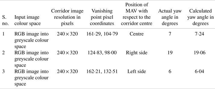
As shown in Figure 8, vanishing point pixel coordinates of (162⋅21, 132⋅51), (161⋅29, 104⋅79) and (124⋅83, 98⋅00) are detected for the estimation of the MAV heading from corridor left, from corridor centre and from corridor right using RGB image converted into a greyscale channel corridor image frame for an image resolution of 240 × 320 pixels. Detected vanishing point coordinates have been used to calculate the yaw angle using Equation (8) for actual yaw angle values of 6, 7, 19, and obtained the estimated yaw angle values of 6⋅04, 7⋅24 and 19⋅06, respectively.
The integration of the connected components algorithm and k-means clustering algorithm in the greyscale channel colour space is used to estimate the MAV's heading and position with respect to the corridor. Table 1 reports the MAV heading and position estimation results.
Estimation of MAV heading and position from the corridor centre towards the left and right of the centre using RGB image into greyscale colour space image frame (image resolution: 240 × 320 pixels)

Figure 9 shows the vanishing points detected in the greyscale channel staircase image frame for the MAV heading from centre towards the right of the staircase using the proposed method.
Vanishing points: (a) vanishing point detection output, (b) input staircase image frame and (c) vanishing point detected in the RGB into greyscale channel staircase image frame

As illustrated in Figure 9, utilising an RGB image converted to a greyscale channel staircase image frame with a 240 × 320 pixel resolution, the vanishing point pixel coordinates of (118⋅29, 74⋅95) were identified for the estimation of the MAV travelling from the staircase centre towards the right of the staircase. Equation (8) was used to calculate the yaw angle using the detected vanishing point coordinates. A yaw angle value of 27⋅09 degrees was computed based on an actual yaw angle value of 27 degrees. The experimental results infer that the proposed position and heading estimation algorithm for GPS-denied corridor environment based on the integrated connected components algorithm and k-means clustering algorithm in the greyscale channel colour space can also be used to estimate the position and heading of the MAV in a GPS-denied staircase environment.
The MAV heading was estimated for the MAV flying from centre towards the right of the corridor. Figure 10 shows the obtained heading estimation results of processing the corridor image frame with an image resolution of 240 × 320 pixels.
MAV heading estimation from the centre towards the right of the corridor (image resolution: 240 × 320 pixels). The y-axis shows the actual and computed yaw angle in degrees, and the x-axis shows the detected vanishing point coordinates in pixels

As seen in Figure 10, utilising an RGB image converted to a greyscale corridor image with a 240 × 320 pixel resolution identifies vanishing point pixel coordinates of (139⋅23, 119⋅64), (117⋅77, 109⋅58), (113⋅70, 77⋅97), (121⋅11, 103⋅41), (195⋅92, 178⋅48), (141⋅37, 126⋅32), (105⋅55, 81⋅18), (89⋅07, 44⋅90), (126⋅91, 113⋅97), (121⋅06, 103⋅45), (117⋅59, 102⋅02), (175⋅49, 162⋅68), (119⋅92, 119⋅33), (125⋅60, 110⋅03), (188⋅89, 82⋅58), (110⋅45, 108⋅09), (187⋅15, 106⋅83), (235⋅34, 154⋅08), (202⋅78, 91⋅43), (265⋅08, 128⋅03), (209⋅80, 91⋅43), (235⋅94, 110⋅22), (212⋅78, 187⋅08), (158⋅37, 148⋅87), (181⋅54, 144⋅83), (244⋅37, 189⋅97), (185⋅26, 153⋅27), (196⋅85,154⋅84), (132⋅13, 118⋅90), (155⋅54, 112⋅42), (151⋅06, 125⋅26), (134⋅48, 120⋅30), (150⋅41, 126⋅32), (107⋅80, 94⋅29), (106⋅92, 107⋅07), (114⋅24, 105⋅49), (113⋅13, 103⋅70), (113⋅49, 91⋅61), (113⋅13, 103⋅70), (114⋅02, 98⋅09) for the estimation of the MAV travelling from the corridor centre towards the right of the corridor. Equation (8) was applied to calculate the yaw angle in the GPS-denied corridor environment using the detected vanishing point coordinates for actual yaw angle values of 10, 20, 27, 19, 30, 9, 29, 40, 15, 19, 21, 21, 19, 16, 21, 23, 14, 34, 23, 41, 25, 32, 35, 13, 15, 42, 19, 23, 13, 4, 5, 12, 5, 17, 13, 11, 12, 17, 22, 23 and obtained the calculated yaw angle values of 9⋅82, 19⋅92, 27⋅52, 19⋅4, 29⋅7, 9⋅31, 29⋅13, 40⋅72, 15⋅65, 19⋅42, 20⋅99, 20⋅72, 18⋅81, 16⋅61, 21⋅49, 23⋅01, 14⋅11, 34⋅56, 23⋅2, 41⋅28, 25⋅56, 32⋅53, 35⋅42, 13⋅54, 15⋅31, 42⋅4, 19⋅19, 22⋅9, 13⋅08, 4⋅19, 4⋅94, 12, 5⋅46, 17⋅06, 13⋅06, 11⋅64, 12⋅54, 17⋅01, 22⋅46, 22⋅99, respectively.
Both RMSE and MAE have been calculated using Equations (9) and (10) for error estimation in heading measurement. Forty image frames with an image resolution of 240 × 320 pixels were used to estimate the heading of the MAV flying from the centre towards the right of the corridor, and the values obtained were 0⋅37 and 0⋅30, respectively.
Figure 11 shows the calculated yaw angle for the MAV heading estimation from the centre towards the left of the corridor for the image resolution of 240 × 320 pixels.
MAV heading estimation from the centre towards the left of the corridor (image resolution: 240 × 320 pixels). The y-axis shows the actual and computed yaw angle in degrees, and the x-axis shows the detected vanishing point coordinates in pixels

As seen in Figure 11, utilising an RGB image converted to a greyscale corridor image with a 240 × 320 pixel resolution identified vanishing point pixel coordinates of (114⋅67, 112⋅79), (118⋅83, 103⋅33), (173⋅22, 162⋅60), (183⋅18, 183⋅16), (70⋅38, 70⋅97), (77⋅32, 65⋅96), (147⋅03, 135⋅77), (133⋅16, 99⋅49), (132⋅51, 70⋅35), (129⋅03, 74⋅36), (134⋅99, 101⋅38), (135⋅17, 106⋅97), (186⋅75, 168⋅15), (181⋅38, 165⋅05), (229⋅47, 188), (147⋅13, 82⋅46), (212⋅82, 191⋅31), (211⋅71, 211⋅50), (161⋅29, 159⋅96), (210⋅99, 192⋅16), (222⋅77, 206⋅34), (168⋅53, 80⋅75), (212⋅39, 212⋅28), (210⋅47, 190⋅46), (211⋅39, 189⋅70), (168⋅45, 92⋅62), (222⋅05, 188⋅82), (200⋅72, 200⋅43), (168⋅54, 80⋅77), (188⋅18, 189⋅66), (183⋅18, 183⋅16), (125⋅94, 126⋅12), (105⋅65, 105⋅95), (105⋅62, 106⋅33), (70⋅38, 70⋅97), (113⋅70, 114⋅05), (111⋅62, 109⋅81), (99⋅43, 98⋅01), (114⋅67, 112⋅79), (79⋅38, 75⋅87) for the estimation of the MAV travelling from the corridor centre towards the left of the corridor. Equation (8) was applied to calculate the yaw angle in the GPS-denied corridor environment using the detected vanishing point coordinates for actual yaw angle values of 21, 20, 20, 29, 40, 39, 10, 15, 25, 25, 14, 13, 24, 22, 39, 18, 36, 41, 18, 36, 41, 18, 43, 36, 36, 13, 37, 37, 18, 32, 29, 16, 25, 25, 40, 21, 22, 28, 21, 37 and obtained the calculated yaw angle values of 20⋅92, 20⋅3, 20⋅39, 29⋅27, 40⋅4, 39⋅46, 9⋅65, 15⋅71, 25⋅3, 24⋅7, 14⋅56, 13⋅15, 24⋅65, 22⋅56, 39⋅01, 18⋅29, 36⋅48, 41⋅21, 18⋅42, 36⋅36, 41⋅65, 18⋅5, 42⋅96, 35⋅84, 35⋅81, 13⋅42, 37⋅67, 36⋅91, 18⋅5, 32⋅05, 29⋅27, 16⋅08, 25⋅06, 25⋅04, 40⋅4, 21⋅25, 22⋅39, 28⋅23, 20⋅92, 37⋅44, respectively.
For an image resolution of 240 × 320 pixels, the error has been estimated using 40 frames for the heading measurement of the MAV using Equations (9) and (10) from centre towards left of the corridor and obtained the RMSE and MAE values of 0⋅37 and 0⋅31, respectively.
As shown in Figure 12, image resolution of 256 × 256 pixels were used to compute the MAV heading from centre towards the right of the corridor, and the yaw angle were calculated using the vanishing point pixel coordinates.
MAV heading estimation from the centre towards the right of the corridor (image resolution: 256 × 256 pixels). The y-axis shows the actual and computed yaw angle in degrees, and the x-axis shows the detected vanishing point coordinates in pixels

As seen in Figure 12, utilising an RGB image converted to a greyscale corridor image with a 256 × 256 pixel resolution identified vanishing point pixel coordinates of (104⋅89, 92⋅91), (79⋅65, 69⋅81), (78⋅25, 55⋅39), (93⋅73, 77⋅80), (113⋅68, 107⋅30), (102⋅86, 101⋅56), (81⋅43, 65⋅37), (99⋅30, 94⋅15), (88⋅11, 43⋅48), (78⋅01, 36⋅84), (149⋅00, 54⋅13), (91⋅86, 18⋅73), (93⋅56, 95⋅02), (75⋅36, 74⋅67), (75⋅00, 98⋅67), (112⋅90, 102⋅57), (108⋅14, 108⋅64), (110⋅62, 106⋅78), (80⋅80, 89⋅58), (94⋅20, 68⋅56) for the estimation of the MAV travelling from the corridor centre towards the right of the corridor. Equation (8) was applied to calculate the yaw angle in the GPS-denied corridor environment using the detected vanishing point coordinates for actual yaw angle values of 18, 30, 34, 25, 11, 16, 31, 19, 36, 39, 31, 42, 20, 30, 25, 13, 12, 12, 25, 28 and obtained the calculated yaw angle values of 18⋅16, 30⋅58, 34⋅51, 25⋅39, 11⋅12, 15⋅9, 31⋅37, 19⋅12, 36⋅13, 39⋅08, 30⋅95, 41⋅95, 20⋅43, 30⋅34, 25⋅32, 13, 12⋅22, 12⋅09, 25⋅42, 28⋅1, respectively.
Using the actual and calculated yaw angles for 20 image frames in Table 3, Equations (9) and (10) obtained the RMSE and MAE values of 0⋅28 and 0⋅22, respectively.
Figure 13 shows the actual and calculated yaw angle for an MAV heading from centre towards the left of the corridor using the corridor image frame with a resolution of 256 × 256 pixels.
MAV heading estimation from the centre towards the left of the corridor (image resolution: 256 × 256 pixels). The y-axis shows the actual and computed yaw angle in degrees, and the x-axis shows the detected vanishing point coordinates in pixels

As seen in Figure 13, utilising an RGB image converted to a greyscale corridor image with a 256 × 256 pixel resolution identified vanishing point pixel coordinates of (119⋅67, 94⋅63), (133⋅29, 56⋅86), (105⋅03, 43⋅95), (110⋅91, 52⋅38), (102⋅00, 44⋅99), (116⋅36, 93⋅27), (33⋅22, 34⋅41), (136⋅31, 119⋅85), (51⋅95, 52⋅30), (72⋅88, 96⋅31), (127⋅40, 112⋅03), (90⋅48, 90⋅84), (52⋅26, 32⋅90), (116⋅06, 92⋅96), (62⋅01, 63⋅01), (152⋅33, 162⋅91), (116⋅38, 97⋅66), (100⋅48, 99⋅99), (67⋅97, 68⋅28), (64⋅44, 64⋅45) for the estimation of MAV travelling from the corridor centre towards the left of the corridor. Equation (8) was applied to calculate the yaw angle in the GPS-denied corridor environment using the detected vanishing point coordinates for actual yaw angle values of 15, 29, 34, 31, 34, 16, 46, 5, 40, 26, 7, 22, 43, 16, 36, 18, 14, 17, 33, 35 and obtained the calculated yaw angle values of 15⋅04, 29⋅13, 34⋅24, 31⋅19, 34⋅19, 15⋅96, 46⋅13, 5⋅19, 39⋅97, 26⋅41, 7⋅11, 22⋅41, 43⋅52, 16⋅12, 35⋅88, 18⋅39, 14⋅24, 17⋅05, 33⋅48, 35⋅07, respectively.
Using the actual and calculated yaw angles for 20 image frames in Table 3, using Equations (9) and (10) obtained the RMSE and MAE values of 0⋅25 and 0⋅20, respectively.
Vanishing point pixel coordinates were detected in the corridor image frame with an image resolution of 480 × 640 pixels for the MAV heading from the centre towards the right of the corridor. Figure 14 shows the calculated yaw angles.
MAV heading estimation from the centre towards the right of the corridor (image resolution: 480 × 640 pixels). The y-axis shows the actual and computed yaw angle in degrees, and the x-axis shows the detected vanishing point coordinates in pixels

As seen in Figure 14, utilising an RGB image converted to a greyscale corridor image with a 480 × 640 pixel resolution identified vanishing point pixel coordinates of (256⋅21, 220⋅68), (223⋅34, 188⋅01), (440⋅32, 360⋅56), (225⋅16, 172⋅10), (371⋅38, 323⋅87), (246⋅83, 247⋅08), (276⋅88, 257⋅60),(248⋅62, 208⋅23), (198⋅81, 180⋅76), (447⋅91, 196⋅26), (285⋅84, 243⋅61), (361⋅42, 314⋅13), (440⋅24, 431⋅11), (343⋅40, 306⋅41), (438⋅26, 413⋅50), (154⋅50, 149⋅29), (278⋅57, 173⋅21), (271⋅23, 270⋅37), (266⋅55, 266⋅88), (407⋅64, 406⋅80) for the estimation of the MAV travelling from the corridor centre towards the right of the corridor. Equation (8) was applied to calculate the yaw angle in the GPS-denied corridor environment using the detected vanishing point coordinates for actual yaw angle values of 15, 24, 35, 26, 22, 17, 11, 18, 29, 29, 8, 19, 43, 16, 41, 38, 18, 13, 14, 38 and obtained the calculated yaw angle values of 15⋅52, 24⋅57, 35⋅36, 25⋅91, 22⋅28, 17⋅02, 10⋅98, 18⋅03, 29⋅33, 29⋅39, 8⋅14, 19⋅48, 43⋅25, 16⋅35, 41⋅18, 38⋅17, 18⋅13, 13⋅46, 13⋅99, 38⋅13, respectively.
For 20 image frames, the RMSE and MAE values were calculated using Equations (9) and (10) for the heading measurement from the centre towards the right of the corridor using an image resolution of 480 × 640 pixels. They obtained the values of 0⋅30 and 0⋅24, respectively.
An image resolution of 480 × 640 pixels has been used for the heading measurement of the MAV from the centre towards the left of the corridor. Figure 15 shows the actual and calculated yaw angles.
MAV heading estimation from the centre towards the left of the corridor (image resolution: 480 × 640 pixels). The y-axis shows the actual and computed yaw angle in degrees, and the x-axis shows the detected vanishing point coordinates in pixels

As seen in Figure 15, utilising an RGB image converted to a greyscale corridor image with a 480 × 640 pixel resolution identified vanishing point pixel coordinates of (118⋅53, 118⋅50), (144⋅47, 144⋅76), (373⋅94, 350⋅43), (356⋅55, 356⋅36), (395⋅01, 358⋅76), (331⋅42, 316⋅81), (245⋅30, 246⋅41), (422⋅81, 397⋅78), (443⋅68, 407⋅74), (118⋅05, 110⋅92), (203⋅37, 203⋅70), (386⋅04, 349⋅38), (197⋅74, 197⋅43), (234⋅15, 215⋅01), (455⋅62, 415⋅17), (258⋅65, 243⋅57), (301⋅17, 282⋅16), (383⋅14, 371⋅84), (443⋅15, 429⋅39), (400⋅03, 359⋅77) for the estimation of the MAV travelling from the corridor centre towards the left of the corridor. Equation (8) was applied to calculate the yaw angle in the GPS-denied corridor environment using the detected vanishing point coordinates for actual yaw angle values of 44, 40, 27, 27, 30, 18, 17, 38, 41, 45, 27, 28, 28, 20, 43, 14, 11, 31, 43, 31 and obtained the calculated yaw angle values of 44⋅43, 39⋅76, 27⋅11, 26⋅93, 30⋅34, 17⋅93, 17⋅34, 38⋅12, 40⋅97, 44⋅95, 26⋅97, 28⋅03, 28⋅34, 20⋅43, 42⋅71, 14⋅36, 10⋅89, 31⋅34, 43⋅26, 30⋅97, respectively.
For 20 image frames with an image resolution of 480 × 640 pixels, Equations (9) and (10) calculated the RMSE and MAE values for the heading measurement from the centre towards the left of the corridor as 0⋅24 and 0⋅20, respectively.
In the image resizing, a 512 × 512 pixels image resolution was used to estimate the MAV heading from the centre towards the right of the corridor, as shown in Figure 16.
MAV heading estimation from the centre towards the right of the corridor (image resolution: 512 × 512 pixels). The y-axis shows the actual and computed yaw angle in degrees, and the x-axis shows the detected vanishing point coordinates in pixels

As seen in Figure 16, utilising an RGB image converted to a greyscale corridor image with a 512 × 512 pixel resolution identified vanishing point pixel coordinates of (214⋅45, 182⋅65), (228⋅40, 230⋅40), (167⋅89, 141⋅02), (226⋅77, 227⋅10), (177⋅48, 184⋅63), (122⋅90, 123⋅24), (196⋅91, 179⋅94), (165⋅65, 167⋅09), (192⋅78, 171⋅86), (262⋅66, 186⋅09), (302⋅93, 279⋅26), (213⋅68, 206⋅93), (131⋅97, 128⋅14), (292⋅90, 292⋅68), (242⋅08, 225⋅94), (233⋅50, 233⋅32), (267⋅88, 249⋅73), (117⋅28, 91⋅17), (120⋅34, 95⋅25), (113⋅15, 104⋅67), (272⋅52, 245⋅62), (134⋅10, 134⋅58), (132⋅33, 132⋅90), (204⋅49, 203⋅86) for the estimation of the MAV travelling from the corridor centre towards the right of the corridor. Equation (8) was applied to calculate the yaw angle in the GPS-denied corridor environment using the detected vanishing point coordinates for actual yaw angle values of 18, 8, 29, 9, 22, 36, 20, 26, 22, 15, 11, 14, 35, 11, 7, 7, 3, 40, 39, 39, 4, 34, 34, 16 and obtained the calculated yaw angle values of 18⋅22, 8⋅36, 29⋅5, 9⋅12, 22⋅5, 36⋅28, 20⋅61, 26⋅34, 22⋅34, 15⋅33, 11⋅56, 14⋅2, 34⋅83, 11⋅49, 7⋅37, 7⋅11, 3, 40⋅08, 39⋅4, 39⋅1, 4⋅35, 33⋅9, 34⋅27, 15⋅97, respectively.
The actual and calculated yaw angles were computed for the MAV heading from the centre towards the right of the corridor based on the vanishing point pixel coordinates detected using 24 image frames with an image resolution of 512 × 512 pixels. RMSE and MAE values were calculated using Equations (9) and (10) and obtained values of 0⋅33 and 0⋅28, respectively.
In Figure 17, an image resolution of 512 × 512 pixels was used to compute the MAV heading from the centre towards the left of the corridor, and the yaw angle has been calculated using the vanishing point pixel coordinates.
MAV heading estimation from the centre towards the left of the corridor (image resolution: 512 × 512 pixels). The y-axis shows the actual and computed yaw angle in degrees, and the x-axis shows the detected vanishing point coordinates in pixels

As seen in Figure 17, utilising an RGB image converted to a greyscale corridor image with a 512 × 512 pixel resolution identified vanishing point pixel coordinates of (72⋅85, 73⋅57), (326⋅41, 325⋅49), (375⋅23, 373⋅89), (351⋅28, 353⋅02), (185⋅31, 184⋅31), (302⋅38, 303⋅30), (234⋅45, 248⋅02), (192⋅61, 218⋅16), (289⋅41, 279⋅07), (185⋅98, 186⋅88), (185⋅37, 172⋅34), (315⋅17, 294⋅15), (336⋅76, 321⋅50), (108⋅96, 109⋅04), (72⋅71, 73⋅97), (108⋅70, 94⋅84), (305⋅58, 302⋅45), (371⋅01, 370⋅11), (236⋅82, 194⋅63), (178⋅38, 162⋅75), (79⋅66, 68⋅57), (274⋅21, 253⋅14), (318⋅94, 295⋅94), (146⋅21, 147⋅85), (203⋅44, 191⋅89), (178⋅04, 157⋅35), (208⋅98, 209⋅52), (344⋅74, 321⋅29), (341⋅42, 317⋅77), (331⋅88, 318⋅75), (359⋅34, 337⋅22), (310⋅54, 299⋅97), (359⋅34, 356⋅82), (354⋅89, 251⋅49), (179⋅01, 178⋅07) for the estimation of the MAV travelling from the corridor centre towards the left of the corridor. Equation (8) was applied to calculate the yaw angle in the GPS-denied corridor environment using the detected vanishing point coordinates for actual yaw angle values of 45, 21, 33, 28, 21, 14, 5, 16, 9, 21, 23, 15, 22, 39, 45, 40, 15, 32, 14, 25, 45, 4, 16, 31, 18, 26, 14, 23, 22, 21, 27, 15, 29, 21, 23 and obtained the calculated yaw angle values of 45⋅27, 21⋅13, 33⋅22, 27⋅97, 21⋅46, 14⋅5, 5⋅12, 16⋅08, 9⋅01, 21⋅02, 23⋅15, 15⋅37, 22⋅1, 39⋅07, 45⋅25, 40⋅45, 14⋅86, 32⋅32, 14⋅1, 25⋅35, 45⋅14, 4⋅11, 16⋅23, 31⋅04, 17⋅94, 26⋅15, 14⋅47, 23⋅28, 22⋅38, 21⋅03, 27⋅18, 15⋅3, 29⋅42, 21⋅14, 23⋅16, respectively.
The actual and calculated yaw angles were computed for the MAV heading from the centre towards the left of the corridor based on the vanishing point pixel coordinates detected using 35 image frames with an image resolution of 512 × 512 pixels. RMSE and MAE values were calculated using Equations (9) and (10) and obtained values of 0⋅25 and 0⋅20, respectively.
Vanishing point pixel coordinates were detected in the corridor image frame with an image resolution of 960 × 1,280 pixels for the MAV heading from the centre towards the right of the corridor. The calculated yaw angles are shown in Figure 18.
MAV heading estimation from the centre towards the right of the corridor (image resolution: 960 × 1280 pixels). The y-axis shows the actual and computed yaw angle in degrees, and the x-axis shows the detected vanishing point coordinates in pixels

As seen in Figure 18, utilising an RGB image converted to a greyscale corridor image with a 960 × 1,280 pixel resolution identified vanishing point pixel coordinates of (404⋅03, 400⋅62), (476⋅95, 476⋅71), (856⋅17, 746⋅84), (692⋅81, 549⋅23), (446⋅99, 385⋅73), (640⋅79, 445⋅47), (995⋅42, 705⋅24), (642⋅56, 444⋅92), (893⋅70, 482⋅53), (889⋅25, 745⋅62), (655⋅68, 572⋅69), (528⋅93, 475⋅41), (402⋅91, 327⋅46), (560⋅32, 425⋅21), (482⋅98, 457⋅88), (572⋅29, 486⋅07), (821⋅42, 614⋅34), (702⋅56, 604⋅36), (702⋅56, 616⋅34), (729⋅96, 675⋅82), (906⋅93, 907⋅10), (517⋅89, 547⋅18), (749⋅77, 714⋅58), (492⋅17, 538⋅42), (598⋅80, 423⋅21), (511⋅81, 321⋅06), (644⋅38, 506⋅45), (350⋅67, 353⋅25) for the estimation of the MAV travelling from the corridor centre towards the right of the corridor. Equation (8) was applied to calculate the yaw angle in the GPS-denied corridor environment using the detected vanishing point coordinates for actual yaw angle values of 27, 19, 35, 10, 24, 4, 41, 4, 28, 37, 11, 13, 30, 11, 18, 8, 25, 16, 17, 24, 46, 16, 28, 18, 8, 23, 3, 33 and obtained the calculated yaw angle values of 27⋅41, 18⋅76, 35⋅58, 10⋅28, 24⋅1, 4⋅11, 41⋅23, 4⋅19, 27⋅86, 37⋅19, 11⋅08, 13⋅03, 30⋅42, 11⋅38, 18⋅27, 8⋅05, 25⋅18, 16⋅17, 17⋅35, 24⋅18, 46⋅37, 16⋅19, 28⋅35, 18⋅32, 8⋅31, 23⋅04, 3⋅19, 33⋅34, respectively.
For 28 image frames with an image resolution of 960 × 1,280 pixels, Equations (9) and (10) obtained the RMSE and MAE values for the heading measurement from the centre towards the right of the corridor, obtaining values of 0⋅27 and 0⋅23, respectively.
The MAV heading was estimated for flying from the centre towards the left of the corridor. Figure 19 shows the obtained heading estimation results of processing the corridor image frame with an image resolution of 960 × 1280 pixels.
MAV heading estimation from the centre towards the left of the corridor (image resolution: 960 × 1,280 pixels). The y-axis shows the actual and computed yaw angle in degrees, and the x-axis shows the detected vanishing point coordinates in pixels

As seen in Figure 19, utilising an RGB image converted to a greyscale corridor image with a 960 × 1280 pixel resolution identified vanishing point pixel coordinates of (475⋅66, 462⋅61), (474⋅06, 461⋅17), (606⋅17, 605⋅51), (607⋅31, 606⋅96), (676⋅89, 676⋅16), (203⋅83, 200⋅77), (203⋅88, 201⋅31), (182⋅48, 160⋅43), (352⋅82, 352⋅66), (186⋅21, 187⋅94), (144⋅14, 145⋅09), (144⋅58, 148⋅12), (215⋅54, 215⋅15), (358⋅37, 290⋅74), (429⋅54, 351⋅49), (557⋅71, 503⋅13), (313⋅55, 312⋅18), (126⋅34, 129⋅08), (338⋅41, 276⋅64), (222⋅91, 205⋅26), (652⋅55, 582⋅77), (500⋅36, 228⋅94), (850⋅09, 826⋅34), (487⋅95, 261⋅15), (547⋅98, 522⋅64), (413⋅43, 378⋅75), (506⋅29, 364⋅15), (672⋅17, 634⋅23), (473⋅50, 453⋅56), (429⋅59, 430⋅59), (228⋅10, 192⋅83), (325⋅18, 299⋅48), (721⋅30, 658⋅45), (305⋅60, 279⋅27), (174⋅49, 171⋅04), (653⋅02, 645⋅70), (190⋅15, 119⋅97), (678⋅73, 547⋅12), (285⋅51, 152⋅25), (597⋅44, 469⋅29) for the estimation of the MAV travelling from the corridor centre towards the left of the corridor. Equation (8) was applied to calculate the yaw angle in the GPS denied corridor environment using the detected vanishing point coordinates for actual yaw angle values of 19, 19, 15, 15, 22, 47, 47, 49, 33, 48, 51, 51, 46, 35, 27, 10, 37, 52, 37, 46, 12, 31, 40, 29, 12, 27, 20, 18, 19, 24, 46, 37, 22, 39, 49, 19, 50, 9, 45, 5 and obtained the calculated yaw angle values of 18⋅99, 19⋅18, 15⋅15, 15⋅27, 22⋅57, 47⋅17, 47⋅15, 49⋅3, 33⋅2, 48⋅34, 51⋅26, 51⋅16, 46⋅18, 35⋅25, 27⋅18, 10⋅09, 37⋅4, 52⋅34, 37⋅15, 46⋅13, 12⋅17, 30⋅9, 40⋅16, 29⋅03, 11⋅93, 27⋅33, 20⋅23, 18⋅16, 19⋅35, 24⋅24, 46⋅29, 37⋅08, 22⋅22, 39⋅09, 49⋅33, 19⋅1, 50⋅2, 9⋅17, 45⋅16, 5⋅22, respectively.
The RMSE and MAE have been calculated using Equations (9) and (10) for error estimation in heading measurement using 40 image frames with an image resolution of 960 × 1280 pixels to estimate the heading of the MAV flying from the centre towards the left of the corridor and obtained values of 0⋅23 and 0⋅20, respectively.
Average RMSE values were calculated using Equations (9) and (10) for the MAV heading from the centre towards the left and right of the corridor and obtained the values of 0⋅27 and 0⋅31, respectively. Therefore, overall RMSE value for the MAV heading estimation is 0⋅29.
Average MAE values were calculated using Equations (9) and (10) for the MAV heading from the centre towards the left and right of the corridor and obtained the values of 0⋅22 and 0⋅25, respectively. Therefore, the overall MAE value for the MAV heading estimation is 0⋅24.
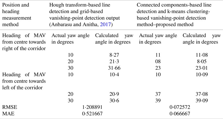
In the Hough transform-based line detection and grid-based vanishing point detection output (Anbarasu and Anitha, Reference Anbarasu and Anitha2017), for error estimation of the MAV heading measurement, a total of 33 corridor image frames were used and RMSE and MAE values of 2⋅84 and 1⋅20 were obtained, which is higher when compared to the proposed k-means clustering-based vanishing-point detection method by processing 287 corridor image frames and obtained the lower RMSE and MAE values of 0⋅29 and 0⋅24, respectively.
The proposed method has been compared with the state-of-the-art method, and the RMSE and MAE values were been calculated for both methods using six image frames, as listed in Table 2.
Comparison of the proposed method with the state-of-the-art method
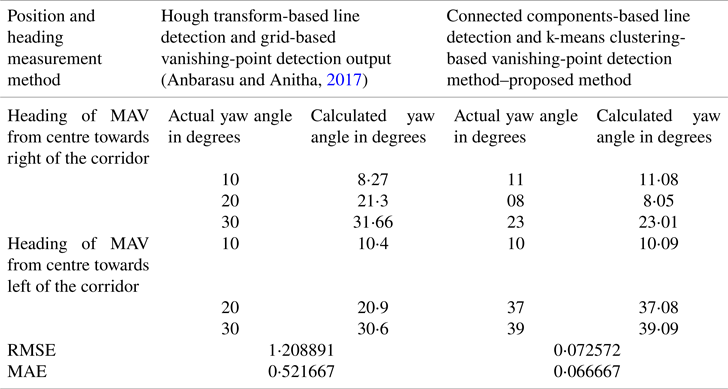
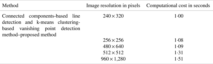
Table 3 lists the processing time for different image resolutions (240 × 320 pixels, 256 × 256 pixels, 480 × 640 pixels, 512 × 512 pixels and 960 × 1280 pixels).
Computational cost of the proposed method
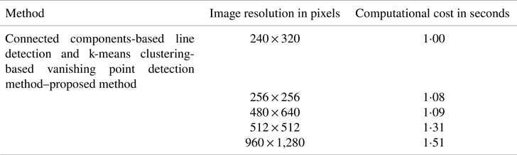
In this study, the vanishing point is not extracted from the intersection of lines, in contrast to other state-of-the-art solutions in the literature. This has significantly lowered our suggested method processing time and computational complexity. From the computational cost, it is inferred that the proposed connected components-based line detection and k-means clustering-based vanishing-point detection method is suitable for robust real-time position and heading estimation for indoor navigation of MAVs.
Lines and vanishing points can be detected even for image frames with the resolution of 120 × 160 pixels and 60 × 80 pixels for the proposed method, as shown in Figure 20, but lines and vanishing points cannot be detected in the state-of-the-art method using Hough transform-based line detection and grid-based vanishing point detection output (Anbarasu and Anitha, Reference Anbarasu and Anitha2017). For the MAV flying from the centre of the corridor to the left, a heading of 31⋅8° was computed for the actual heading of 32° using an image resolution of 120 × 160 pixels and detected vanishing point pixel coordinates of (50⋅14, 37⋅79). The experimental results infer that errors in the measurement of the heading have been decreased for low-image resolutions of 120 × 160 and 60 × 80 pixels compared to the state-of-the-art method (Anbarasu and Anitha, Reference Anbarasu and Anitha2017).
Vanishing point detection for low image resolutions: (a) 120 × 160 pixels and (b) 60 × 80 pixels

Single lines can be detected, but the vanishing point cannot be detected using the k-means clustering method for image frames with very low resolutions of 30 × 40 and 15 × 20 pixels. To cluster the line data for vanishing point detection, a minimum of four lines must be detected using the connected component algorithm in the corridor image frames. Real-time corridor video has been processed, and the proposed method is suitable for real-time heading measurement for indoor MAVs has an accuracy of ± 0⋅5°.
7. Conclusions
This paper has proposed an efficient vanishing point detection for MAV position and heading estimation using the integrated connected components algorithm and the k-means clustering algorithm. Extracted vanishing point pixel coordinates using the perspective projection in the successive corridor image frames were used to compute the MAV heading from the centre to the left or right of the corridor by computing the Euclidean distance between the image centre mid-pixel coordinates at the last row of the image. The lowest computational cost of the proposed method was obtained using different image resolutions of 256 × 256 pixels, 240 × 320 pixels, 480 × 640 pixels, 960 × 1280 pixels and 512 × 512 pixels. Similarly, the results showed that a ±0⋅5° better heading accuracy is acquired from the proposed k-means clustering-based vanishing point detection method compared with the grid-based vanishing-point detection method and is suitable for real-time MAV navigation in a GPS-denied corridor environment.
From the experimental results, it is inferred that the proposed integrated connected components algorithm and the k-means clustering algorithm in the greyscale channel colour space have been used to estimate the heading and position of the MAV in GPS-denied corridor and staircase environments. Future research should develop hyper-opponent colour channel space-based vanishing-point detection methods for accurate MAV heading estimation in the GPS-denied corridor and staircase environments.
Conflict of interest
None.