





1. Introduction
The behaviour of particles immersed in a viscous fluid in the low-Reynolds-number regime is inevitably affected by hydrodynamic interactions with other nearby bodies, such as other particles, fluid interfaces and solid walls confining the fluid. These interactions, that are the origin of fundamental phenomena, including the enhanced resistance on bodies (Hill & Power Reference Hill and Power1956), the intrinsic convection of suspensions (Beenakker & Mazur Reference Beenakker and Mazur1985), the Segre–Silberberg effect (Segre & Silberberg Reference Segre and Silberberg1961), to quote just few of them, become significant whenever the characteristic particle length  $\ell _b$ is comparable with the characteristic separation distance
 $\ell _d$ from the nearest boundary. Therefore, the accurate description of fluid–particle interactions is of paramount relevance in several areas of microfluidics, such as separation devices (Huang et al. Reference Huang, Cox, Austin and Sturm2004; Striegel & Brewer Reference Striegel and Brewer2012; Cerbelli, Giona & Garofalo Reference Cerbelli, Giona and Garofalo2013), capillary transport (Goldsmith & Skalak Reference Goldsmith and Skalak1975; Popel & Johnson Reference Popel and Johnson2005; Undvall et al. Reference Undvall, Garofalo, Procopio, Qiu, Lenshof, Laurell and Baasch2022), dynamics of micro-swimmers (Lauga Reference Lauga2020) and active particles (Michelin Reference Michelin2023), where, by definition, the micrometric (or even sub-micrometric) characteristic dimension of the fluid domain may be of the same order of magnitude of the particle size.
Microfluidics is typically characterised by low Reynolds numbers (apart from the specific applications referred to as inertial microfluidics Di Carlo Reference Di Carlo2009; Zhang et al. Reference Zhang, Yan, Yuan, Alici, Nguyen, Warkiani and Li2016) so that, in most of the cases, the fluid can be considered in the Stokes regime and, when the inertia of the fluid becomes significant ( $Re \sim 1$) but not too large, it can be treated by perturbative methods with respect to the Stokes-flow solution (Cox & Brenner Reference Cox and Brenner1968; Ho & Leal Reference Ho and Leal1974). Although hydrodynamic problems related to particles in confined fluids can be approached by means of typical numerical methods for solving the Stokes equation (such as the finite-element method (FEM) (De Corato et al. Reference De Corato, Greco, D'Avino and Maffettone2015; Venditti et al. Reference Venditti, Cerbelli, Procopio and Adrover2022) and boundary-element method (BEM) (Pozrikidis Reference Pozrikidis1992), a deeper mathematical understanding of fluid–particle interactions can be beneficial in order to overcome, by means of explicit analytical solutions, the limits and shortcomings of the numerical approaches, to improve the current numerical methods (such as Stokesian dynamics Brady & Bossis Reference Brady and Bossis1988) and develop new ones, and to explain and predict the non-intuitive flow and transport phenomena that may occur at the microscale.
One of the main difficulties in the analytical approaches to multibody systems is the intrinsic geometric complexity induced by the presence of bodies and surfaces of different shapes where to impose the boundary conditions (BCs). This difficulty holds even when dealing with the most regular bodies (such as spheres or ellipsoids) and the simplest confinement geometries (for example, planar or cylindrical walls), since the union of many bodies, in most of the cases, breaks down the original symmetries making impossible to find a coordinate system which permit to express simultaneously all the BCs in a simple mathematical way. This is the reason why the only exact solutions available in the literature regard axisymmetric geometries of the hydrodynamic problem (where the symmetry is defined with respect to a suitable orthogonal system of curvilinear coordinates). This is the case of the resistance of a rigid sphere close to a plane considering no-slip BCs (Jeffery Reference Jeffery1915; Brenner Reference Brenner1961; Dean & O'Neill Reference Dean and O'Neill1963; O'Neill Reference O'Neill1964), Navier-slip BCs (Goren Reference Goren1979) and phoretic slip BCs (Desai & Michelin Reference Desai and Michelin2021), the resistance between two spheres moving relative to each other (O'Neill & Majumdar Reference O'Neill and Majumdar1970) and of the resistance of a sphere at the centre of a cylindrical channel, translating parallelly to the symmetry axis assuming no-slip BCs (Haberman & Sayre Reference Haberman and Sayre1958). Only in few cases an ambient flow has been also considered, such as in (Haberman & Sayre Reference Haberman and Sayre1958), for a sphere immersed in a Poiseuille flow and in Pasol et al. (Reference Pasol, Chaoui, Yahiaoui and Feuillebois2005), where a sphere immersed in an axisymmetric polynomial flow bounded by a plane wall has been analysed.
Whereas, for the majority of the confined systems considered in the literature, approximate analytical solutions have been obtained under the assumption of asymptotic approximations, by using mainly a lubrication method for short-range interactions ( $\ell _d \ll \ell _b$) and a reflection method for long-range interactions (
 $\ell _d \gg \ell _b$). In some cases, such as that of the resistance of two rigid moving spheres with no-slip BCs (Jeffrey & Onishi Reference Jeffrey and Onishi1984), the solution has been approximated by matching the asymptotic solutions.
In the case of short-range interactions, many specific solutions are available in the literature, such as the resistance on a sphere near a plane by considering both no-slip (Cox & Brenner Reference Cox and Brenner1967b; Goldman, Cox & Brenner Reference Goldman, Cox and Brenner1967) and Navier-slip (Hocking Reference Hocking1973) BCs, and a general lubrication theory, regardless of the shape of the surfaces in close contact, has been developed by Cox (Reference Cox1974) assuming no-slip BCs.
On the other hand, in the case of long-range interactions, the reflection method (in its multifaceted variations (Happel & Brenner Reference Happel and Brenner1983)) is commonly employed to obtain the leading-order terms for the series expansion in powers of  $\ell _b/\ell _d$ of the particle transport parameters, such as resistance, mobility and diffusivity. The reflection method, developed by Smoluchowski (Reference Smoluchowski1911) (see Happel & Brenner Reference Happel and Brenner1983, p. 236) in order to match the BCs of Stokes flows on a system of
 $n$ spheres, consists of expressing the total flow (i.e. the solution of the Stokes equations with BCs assigned simultaneously on each sphere) as a series of an infinite number of flows satisfying Stokes equations with BCs assigned separately on each body considered in a unbounded domain. For example, a simple version of this method, to obtain the exact flow in the case of two moving spheres, can be summarised as follows: the first term of the series is the flow due to the motion of the first sphere considered in the unbounded fluid, which generates, in turn, a flow on the domain occupied by the second sphere; the second term of the series corrects the flow on the surface of the second sphere generating a flow on the domain of the first sphere and so on. A similar ping-pong correction at the boundaries of the two spheres proceeds iteratively. Although the Stokes equations and the BCs of the global problem are formally satisfied, this procedure is affected by two main limitations: (i) it is not easy to obtain analytical expressions for the solutions of the infinite system of Stokes problems involved even for the simplest geometries; (ii) the convergence of the series can be ensured only for some specific problems, and it is still an open question in the general case.
For example, as regards the second limitation, convergence has been proved heuristically for two equal spheres moving with the same velocity for all the separation distances (Happel & Brenner Reference Happel and Brenner1983, p. 259), but in the case of three equally separated spheres it has been shown that the reflection method does not converge if the distance between the centres of the spheres is smaller than  $2.16$ times the radius of the spheres (Ichiki & Brady Reference Ichiki and Brady2001). In fact, as shown by Höfer & Velázquez (Reference Höfer and Velázquez2018), if particle velocities are imposed by Dirichlet BCs, the method converges only for diluted systems enclosed in an finite volume; whereas, as proved by Luke (Reference Luke1989) using a variational method, in the case of suspensions with
 $n$ particles enclosed in a finite volume, the convergence of the reflection method is ensured regardless of the particles concentration, if particle velocities are not assigned, i.e. if they move under the action of an external force as in the case of sedimentation phenomena.
Therefore, given that the convergence is ensured only for  $\ell _d \gg \ell _b$ and that the exact evaluation of the terms in the series is feasible only for the first ones, i.e. the first corrections to the unbounded approximation, reflection methods are widely employed to model very long range interactions between particles. The main fields of application are in the analysis of suspensions, indirectly applied in Stokesian dynamics (Durlofsky, Brady & Bossis Reference Durlofsky, Brady and Bossis1987; Brady & Bossis Reference Brady and Bossis1988) under the form of inverting the particle–particle interaction mobility matrix (Ichiki & Brady Reference Ichiki and Brady2001), and in the analysis of confined systems, mainly considering the interaction between a single particle with the walls of the confinement, such as a sphere or a spheroid near planar (Swan & Brady Reference Swan and Brady2007, Reference Swan and Brady2010; Mitchell & Spagnolie Reference Mitchell and Spagnolie2015) or cylindrical (Goldsmith & Mason Reference Goldsmith and Mason1962; Sonshine, Cox & Brenner Reference Sonshine, Cox and Brenner1966; Hasimoto Reference Hasimoto1976) walls.
However, the convergence of the method even for touching bodies, such as in the case of two translating spheres or in the case of the Luke's suspensions, and the relative small breakdown gap ( $\sim 0.16\, \ell _b$), computed by Ichiki & Brady (Reference Ichiki and Brady2001) for three translating spheres, suggest that, if all the terms of the series were evaluated exactly, reflection method should be a valid approach to provide exact solutions not only in the asymptotic limit
 $\ell _d \gg \ell _b$, but also in a closer region
 $\ell _d \sim \ell _b$, albeit external to the lubrication range
 $\ell _d \ll \ell _b$. A general theory, furnishing the reflection solution regardless of the geometry of the bodies involved, has been developed by Brenner (Reference Brenner1962, Reference Brenner1964a) and Cox & Brenner (Reference Cox and Brenner1967a) for obtaining the resistance on an arbitrary body immersed in an arbitrarily confined Stokesian fluid, that can be also regarded as confined by a second fixed body. In Brenner (Reference Brenner1962, Reference Brenner1964a), the first-order correction with respect to the unbounded approximation of the hydrodynamic resistance (force and torque) on a body rigidly moving (translating and rotating) is provided in terms of the resistance matrix of the body in the unbounded fluid and the Stokes's Green function of the domain of the confined fluid without the body inclusion; whereas in Cox & Brenner (Reference Cox and Brenner1967a) a formal expression for the resistance in the large-distance limit is derived, considering also an arbitrary ambient flow, in terms of unspecified tensors depending separately on the geometry of the body and on the geometry of the confinement. The formal approach by Cox & Brenner (Reference Cox and Brenner1967a) is not easily amenable to a simple practical implementation as regards the higher-order terms in the expansion, and for this reason it has remained as a beautiful formal development disjoint from practical implementation in confined flows.
In this work we develop a novel approach, amenable to practical implementation, in the theory of the hydrodynamic interactions between a body in a confined fluid and the confinement walls, by providing exact reflection solutions for the fluid flow in the system and for the grand-resistance matrix on the body (force, torque and higher moments). We express the global solution in terms of well-defined tensors depending separately on the geometry of the body and on the geometry of the confinement: moments on the body in the unbounded fluid (or the Faxén operators of the body), and multipoles of the domain of the confinement (hence, derivatives of the confined Green function). Unlike the tensors appearing in the expressions for the resistance on the body provided by Cox & Brenner (Reference Cox and Brenner1967a), these tensors, when not yet available in the literature, can be directly evaluated by classical analytical or numerical methods in all the practical cases of interest. Furthermore, we consider BCs on the body more general than the no-slip case, requiring only that these BCs satisfy the principle of BC reciprocity as defined in Procopio & Giona (Reference Procopio and Giona2024). For instance, Navier-slip and many other fluid–fluid boundary conditions of common hydrodynamic practice fall in this class.
To this aim, we enforce the bitensorial formulation (Poisson, Pound & Vega Reference Poisson, Pound and Vega2011) of the Stokes singularities developed by Procopio & Giona (Reference Procopio and Giona2023) in dealing with the entries of the two-point-dependent tensorial field (in hydrodynamics these fields depend simultaneously on the position of fluid element and on the position of the body in the confinement). Furthermore, we make use of the results derived in Procopio & Giona (Reference Procopio and Giona2024) in order to express the hydrodynamics of a body with arbitrary BCs (requiring solely BC reciprocity) in ambient flows generated by the walls of the confinement, which turn out to be highly non-trivial flows even in the simplest case of translation motion.
The article is organised as follows. Section 2 states the problem and provides the definition of the two simpler sub-problems, the solution of which permits to obtain the analytic expression for the global confined hydrodynamics: (i) the Faxén operators of the body and (ii) the multipoles in the domain of the confinement. In § 3, we derive the exact expression for the terms entering in the reflection expansion, showing that they can be expressed as the product of suitable tensorial quantities depending on the volume moments on the body immersed in the ambient flows associated with the regular parts of the bounded multipoles. In § 4 we introduce a generalised matrix notation for tensorial systems more compact than the componentwise representation in terms of the entries of each individual tensor, and we obtain a simple expression for the global velocity field. Moreover, by using the properties of infinite matrices (Cooke Reference Cooke1950), we show in Appendix A that the convergence of the method is ensured for  $\ell _d \gtrsim 2.65 \ell _b$. This does not mean that the series expansion could not converge under more general conditions, although it is reasonable to hypothesise that there exist a constant
 $\varGamma = O(1) >0$, depending on the geometry of the problem, such that the reflection solution converges for
 $\ell _d >\varGamma \ell _b$. In § 5, we provide the exact reflection formulae for force, torque and higher-order moments on the body. The estimate of the error resulting in truncating the exact solutions by considering only lower-order multi-pole (or Faxén operators) is addressed in § 6. We also analyse the truncation error made in classical literature works in the field, specifically in Brenner (Reference Brenner1962, Reference Brenner1964a) and in Swan & Brady (Reference Swan and Brady2007, Reference Swan and Brady2010), and we extend these approximate approaches to more general hydrodynamic problems than those for which they were originally developed. In § 7 we compare and contrast the reflection solution obtained with the present theory (using Faxén operators and bounded multi-pole available in the literature), approximated to the order
 $O (\ell _b/\ell _d)^5$, with the exact solution of a sphere translating and rotating near a planar wall, and we provide the expressions for forces and torques considering the more general situation of Navier-slip BCs assumed at the surface of the body. Finally, in § 8, we investigate the effect of the shape and of the orientation on the hydrodynamic interactions between the body and the confinement. Specifically, by using the approximated expressions obtained in § 6, we estimate the resistance matrix truncated to the order
 $O(\ell _b/\ell _d)^4$ of a prolate spheroid near a plane wall by solely employing the zeroth-order Faxén operator available in the literature (Hasimoto Reference Hasimoto1983; Kim Reference Kim1985) for no-slip BCs. This case study shows how it is possible to obtain accurate hydromechanical effects using lower-order approximations for complex geometries of the system. In fact, by comparing the results obtained with numerical FEM simulation, we show that approximated solutions provide correctly the far-field hydrodynamic interaction independently of the orientation and the shape of the body. We also address the effect of the confinement on the lift force experienced by the spheroid.
2. Statement of the problem
Consider a rigid body immersed in a Newtonian fluid with viscosity  $\mu$ at vanishing Reynolds number. Let
 $V_b \subset \mathbb {R}^3$ be the domain representing the space occupied by the body and
 $V_f$ the space occupied by the fluid domain. The surface bounding the body is
 $S_b$, whereas the surface bounding the fluid is
 $S_b \cup S_w \cup S_\infty$, where
 $S_w$ is the surface bounding externally the fluid and considered in the proximity of the body, and
 $S_\infty$ the boundary at infinity, i.e. any surface considered infinitely far from the body. See the schematic representation of the system geometry in figure 1.
Schematic representation of geometry of the system.

The body is immersed in an ambient flow  $(\boldsymbol{u}(\boldsymbol{x}), \boldsymbol{\rm \pi} (\boldsymbol{x}))$, which is defined as any flow, regular at the surface of the body
 $S_b$, satisfying the Stokes equations (Kim & Karrila Reference Kim and Karrila2005). Considering no-slip BCs on
 $S_w$, the Stokes equations for the ambient flow read
 \begin{equation} \left. \begin{gathered} - \boldsymbol{\nabla} \boldsymbol{\cdot} \boldsymbol{\rm \pi} (\boldsymbol{x}) = \mu \Delta \boldsymbol{u} (\boldsymbol{x})- \boldsymbol{\nabla} p(\boldsymbol{x}) = 0,\\ \boldsymbol{\nabla} \boldsymbol{\cdot} \boldsymbol{u} (\boldsymbol{x}) = 0, \quad \boldsymbol{x} \in V_f \cup V_b,\\ \boldsymbol{u}(\boldsymbol{x})= 0, \quad \boldsymbol{x} \in S_w, \end{gathered} \right\} \end{equation}
where  $\boldsymbol{u}(\boldsymbol{x})$ represents the velocity field,
 $p(\boldsymbol{x})$ the pressure field and
 \begin{equation} \boldsymbol{\rm \pi} (\boldsymbol{x})= p(\boldsymbol{x}) I- \mu (\boldsymbol{\nabla} \boldsymbol{u}(\boldsymbol{x})+\boldsymbol{\nabla} \boldsymbol{u}(\boldsymbol{x})^t) \end{equation}
is the stress tensor. In (2.2)  $I$ represents the identity matrix and the superscript ‘
 $t$’ denotes the transposition operation for a matrix.
Assuming linear homogeneous BCs at the surface of the body  $S_b$, expressed by a generic linear operator
 $\mathcal {L}[\, ]$ acting on the velocity at the surface of the body (this implies that
 $\mathcal {L}[\boldsymbol{v}(\boldsymbol{x}) ]$ at the point
 ${\boldsymbol x} \in S_b$ may depend not only on the velocity
 $\boldsymbol{v}(\boldsymbol{x})$ but also on its derivatives at that point), and no-slip BCs at the surface of the confinement
 $S_w$, the total (or disturbed) flow (
 $\boldsymbol{v}(\boldsymbol{x})$,
 $\boldsymbol{\sigma }(\boldsymbol{x})$) is
 \begin{equation} \left. \begin{gathered} - \boldsymbol{\nabla} \boldsymbol{\cdot} \boldsymbol{\sigma} (\boldsymbol{x}) = \mu \Delta \boldsymbol{v} (\boldsymbol{x})- \boldsymbol{\nabla} s(\boldsymbol{x}) = 0,\\ \boldsymbol{\nabla} \boldsymbol{\cdot} \boldsymbol{v} (\boldsymbol{x}) = 0, \quad \boldsymbol{x} \in V_f,\\ \mathcal{L}[ \boldsymbol{v} (\boldsymbol{x})]=0,\quad \boldsymbol{x} \in S_b,\\ \boldsymbol{v}(\boldsymbol{x})=0, \quad \boldsymbol{x} \in S_w, \end{gathered} \right\} \end{equation}
with the obvious meaning for  $\boldsymbol{v} (\boldsymbol{x})$,
 $s(\boldsymbol{x})$, and
 $\boldsymbol{\sigma } (\boldsymbol{x})$, representing velocity, pressure and stress tensor fields of the total flow, respectively. Henceforth, we require that the BCs expressed by the linear operator
 $\mathcal {L}[\, ]$, satisfy the following condition at the surface of the body: for any couple of flows
 $(\boldsymbol{v}'(\boldsymbol{x}), \boldsymbol{\sigma }'(\boldsymbol{x}))$ and
 $(\boldsymbol{v}''(\boldsymbol{x}), \boldsymbol{\sigma }''(\boldsymbol{x}))$ solution of (2.3), the following identity holds:
 \begin{equation} \int_{S_b} (\boldsymbol{v}'(\boldsymbol{x}) \boldsymbol{\cdot} \boldsymbol{\sigma}''(\boldsymbol{x}) - \boldsymbol{v}(\boldsymbol{x}) \boldsymbol{\cdot} \boldsymbol{\sigma}'(\boldsymbol{x})) \boldsymbol{\cdot} \boldsymbol{n}(\boldsymbol{x}) \,{\rm d}S = 0, \end{equation}
where  $\boldsymbol{n}(\boldsymbol{x})$ is the unitary normal vector outwardly oriented with respect to the body as shown in figure 1. This condition has been introduced and thoroughly discussed in Procopio & Giona (Reference Procopio and Giona2024) in connection to the concept of the Hinch–Kim dualism, and it is referred to as the condition of BC reciprocity. BCs satisfying (2.4), are therefore called reciprocal BCs. As it will become clear in the remainder, the assumption of BC reciprocity, coupled with the linearity of the BCs expressed by the operator
 $\mathcal {L}[\,]$, are the necessary prerequisites in the development of the present theory. Linear reciprocal BCs are, for example, no-slip
 $\boldsymbol{v}(\boldsymbol{x})=0$, complete slip
 $\boldsymbol{\sigma }(\boldsymbol{x})=0$ and Navier-slip BCs
 \begin{equation} \boldsymbol{v}(\boldsymbol{x})+\dfrac{\lambda}{\mu} \boldsymbol{n}(\boldsymbol{x})\boldsymbol{\cdot} \boldsymbol{\sigma}(\boldsymbol{x})\boldsymbol{\cdot} \boldsymbol{t}(\boldsymbol{x})=0 \end{equation}
with  $\lambda$ being the slip length and
 $\boldsymbol{t}(\boldsymbol{x})$ an unitary base vectors tangents to the surface of the body. On the other hand, BCs representing the interaction of the Stokes fluid with a non-Newtonian fluid, for example, are not reciprocal because the reciprocity theorem does not hold in the body domain.
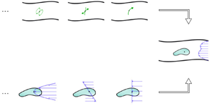
In the next paragraph, the solution of the problem (2.3) is expressed in terms of the hydrodynamic solutions of two simpler problems related separately to the confinement of the fluid and to the body: (i) the Green function of the Stokes equations in the domain of the confinement  $V_f \cup V_b$ and (ii) the geometrical moments of the body in the unbounded fluid. See the schematic representation in figure 2. For this reason, it is useful to define these solutions and discuss briefly their formal properties, introducing and clarifying in this way the notation that we use throughout this article.
Schematic representation of the decomposition of the main problem (a body in a confined fluid with an ambient flow) in problems separately related to the geometry of the confinement and of the particle: (i) multipoles of the confinement (at the top) centred at the position point (e.g. the barycentric coordinate) in the volume the body; (ii) flows around the body in  $n$th-order ambient flows centred at the position of the body provided by the Faxén operators (at the bottom). Green arrows in (a) represent concentrated forces whereas blue arrows in (b) represent velocity fields. The black dot is the position point of the body.

2.1. Green function of the confinement
As discussed in Procopio & Giona (Reference Procopio and Giona2023), the Green function in the confined domain  $V_f \cup V_b$ is a bitensorial field, hence a field depending on two points (called field and source points) with entries at both points expressed, in principle, in different coordinate systems.
The Green function  $G_{a \beta } (\boldsymbol{x},\boldsymbol{\xi })$ of the confined flow is the solution of the equations
 \begin{equation} \left. \begin{gathered} -\boldsymbol{\nabla}_b \varSigma_{a b \beta}(\boldsymbol{x},\boldsymbol{\xi})= \Delta G_{a \beta} (\boldsymbol{x},\boldsymbol{\xi})-\boldsymbol{\nabla}_a P_{\beta} (\boldsymbol{x},\boldsymbol{\xi}) ={-}8{\rm \pi} \delta_{a \beta}\delta(\boldsymbol{x}-\boldsymbol{\xi}),\\ \boldsymbol{\nabla}_a G_{a \beta}(\boldsymbol{x},\boldsymbol{\xi}) = 0, \quad \boldsymbol{x}, \boldsymbol{\xi} \in V_f \cup V_b,\\ G_{a \beta} (\boldsymbol{x},\boldsymbol{\xi})= 0, \quad \boldsymbol{x} \in S_w \cup S_\infty, \end{gathered} \right\} \end{equation}
where  $G_{a \beta } (\boldsymbol{x},\boldsymbol{\xi })$,
 $P_{\beta } (\boldsymbol{x},\boldsymbol{\xi })$,
 $\varSigma _{a b \beta }(\boldsymbol{x},\boldsymbol{\xi })$ are the associated velocity, pressure and stress tensor field. In (2.6) and in the remainder, the notation of the bitensor calculus is applied: (i) Latin letters
 $a,b,\ldots = 1,2,3$ are used for indices referred to the entries of the tensorial entities at the field point
 $\boldsymbol{x}$, with Greek letters
 $\alpha, \beta,\ldots = 1,2,3$ for indices referred to the entries of the tensorial entities at the source points (i.e. the poles of the singularity)
 $\boldsymbol{\xi }$; (ii) Einstein's summation convention is adopted; and (iii)
 $\boldsymbol {\nabla }_a$, with the Latin index, is the gradient with respect to the field point
 $\boldsymbol{x}$, while
 $\boldsymbol {\nabla }_\beta$, with the Greek index, is the gradient with respect to the source point
 $\boldsymbol{\xi }$.
It is useful to define also the regular part of the Green function  $(W_{a \beta }(\boldsymbol{x},\boldsymbol{\xi }), Q_\beta (\boldsymbol{x},\boldsymbol{\xi }))$ as the bitensorial fields solving the problem
 \begin{equation} \left. \begin{gathered} -\boldsymbol{\nabla}_b T_{a b \beta}(\boldsymbol{x},\boldsymbol{\xi})= \Delta W_{a \beta} (\boldsymbol{x},\boldsymbol{\xi})-\boldsymbol{\nabla}_a Q_{\beta} (\boldsymbol{x},\boldsymbol{\xi}) = 0,\\ \boldsymbol{\nabla}_a W_{a \beta}(\boldsymbol{x},\boldsymbol{\xi}) = 0, \quad \boldsymbol{x}, \boldsymbol{\xi} \in V_f \cup V_b,\\ W_{a \beta} (\boldsymbol{x},\boldsymbol{\xi})={-}S_{a \beta}(\boldsymbol{x}-\boldsymbol{\xi}), \quad \boldsymbol{x} \in S_w \cup S_\infty, \end{gathered} \right\} \end{equation}
where  $S_{a \beta }(\boldsymbol{x}-\boldsymbol{\xi })$ is the Stokeslet (Pozrikidis Reference Pozrikidis1992; Kim & Karrila Reference Kim and Karrila2005), i.e. the bitensorial velocity field of the unbounded Green function
 \begin{equation} S_{a \beta}(\boldsymbol{x}-\boldsymbol{\xi})=\dfrac{\delta_{a \beta}}{|(\boldsymbol{x}-\boldsymbol{\xi})|}+\dfrac{(\boldsymbol{x}-\boldsymbol{\xi})_a(\boldsymbol{x}-\boldsymbol{\xi})_\beta}{|(\boldsymbol{x}-\boldsymbol{\xi})|^3}. \end{equation}
Therefore, the bounded Green function can be written as the superposition of a regular field  $W_{a \beta }(\boldsymbol{x},\boldsymbol{\xi })$ and a singular contribution given by the Stokeslet
 \begin{equation} G_{a \beta}(\boldsymbol{x},\boldsymbol{\xi})=S_{a \beta}(\boldsymbol{x}-\boldsymbol{\xi})+W_{a \beta} (\boldsymbol{x},\boldsymbol{\xi}). \end{equation}
By differentiating (2.9) at the pole, higher-order singularities in the domain  $V_b \cup V_f$ are obtained. For example, the
 $n$th-order multipole, with
 $n=1,2,\ldots$, is obtained by
 \begin{equation} \boldsymbol{\nabla}_{\boldsymbol{\beta}_n} G_{a \beta}(\boldsymbol{x},\boldsymbol{\xi})= \boldsymbol{\nabla}_{\boldsymbol{\beta}_n} S_{a \beta}(\boldsymbol{x}-\boldsymbol{\xi})+ \boldsymbol{\nabla}_{\boldsymbol{\beta}_n} W_{a \beta} (\boldsymbol{x},\boldsymbol{\xi}), \end{equation}
where bold index  $\boldsymbol{\beta }_n= \beta _1 \ldots \beta _n$ denotes a multi-index and
 $\boldsymbol {\nabla }_{\boldsymbol{\beta }_n}= \boldsymbol {\nabla }_{\beta _1} \ldots \boldsymbol {\nabla }_{\beta _n}$ is a compact notation for
 $n$th-order differentiation.
2.2. Moments on the body and Faxén operators
Let us briefly define the  $n$th-order moments, the
 $(m,n)$th-order geometrical moments and the
 $n$th-order Faxén operators of a body, addressed in more detail in Procopio & Giona (Reference Procopio and Giona2024).
Consider the same body immersed in an ambient flow ( $\boldsymbol{u}(\boldsymbol{x}),\boldsymbol{\rm \pi} (\boldsymbol{x})$) in the unbounded domain. The disturbance flow (
 $\boldsymbol{w}(\boldsymbol{x})$,
 $\boldsymbol{\tau }(\boldsymbol{x})$) generated by the body immersed in the ambient flow is solution of
 \begin{equation} \left. \begin{gathered} - \boldsymbol{\nabla} \boldsymbol{\cdot} \boldsymbol{\tau} (\boldsymbol{x}) = \mu \Delta \boldsymbol{w} (\boldsymbol{x})- \boldsymbol{\nabla} q(\boldsymbol{x}) = 0,\\ \boldsymbol{\nabla} \boldsymbol{\cdot} \boldsymbol{w} (\boldsymbol{x}) = 0, \quad \boldsymbol{x} \in V_f,\\ \mathcal{L}[ \boldsymbol{w} (\boldsymbol{x})]={-}\mathcal{L}[ \boldsymbol{u}(\boldsymbol{x}) ], \quad \boldsymbol{x} \in S_b,\\ \boldsymbol{w}(\boldsymbol{x})=0, \quad \boldsymbol{x} \rightarrow \infty, \end{gathered} \right\} \end{equation}
where  $\boldsymbol{w}(\boldsymbol{x})$,
 $q(\boldsymbol{x})$ and
 $\boldsymbol{\tau }(\boldsymbol{x})$ are the associated disturbance velocity, pressure and stress tensor fields accounting for the hydrodynamics at the surface
 $S_b$ of the rigid body due to the interaction with the ambient flow
 $\boldsymbol{u}(\boldsymbol{x})$.
To begin with, consider the entries  $\psi _a(\boldsymbol{x})$ of any force field distribution, with compact support belonging to
 $V_b$, such that the Ladyzhenskaya (Reference Ladyzhenskaya2014) volume potential reads
 \begin{equation} \dfrac{1}{8 {\rm \pi}\mu} \int_{V_b} \psi_\beta(\boldsymbol{\xi}) S_{a \beta}(\boldsymbol{x}-\boldsymbol{\xi}) \,{\rm d}V(\boldsymbol{\xi})= {w}_a(\boldsymbol{x}) \quad \boldsymbol{x} \in S_b . \end{equation}
Next, the  $n$th-order moments on the body immersed in a generic ambient flow
 $\boldsymbol{u}(\boldsymbol{x})$, generating a disturbance field at the surface of the body
 $\boldsymbol{w}(\boldsymbol{x})$, are defined as
 \begin{equation} M_{\beta \boldsymbol{\beta}_n}(\boldsymbol{\xi})= \int _{V_b} (\boldsymbol{x}-\boldsymbol{\xi})_{\boldsymbol{\beta}_n} \psi_\beta(\boldsymbol{x}) \,{\rm d}V(\boldsymbol{x}) \quad \boldsymbol{\xi} \in V_b , \end{equation}
where  $(\boldsymbol{x} - \boldsymbol{\xi })_{\boldsymbol{\beta }_n}=(\boldsymbol{x} - \boldsymbol{\xi })_{\beta _1} \ldots (\boldsymbol{x} - \boldsymbol{\xi })_{\beta _n}$ and where
 $(\boldsymbol{x}-\boldsymbol{\xi })_{\beta }=g_{\beta a}(\boldsymbol{\xi },\boldsymbol{x})(\boldsymbol{x}-\boldsymbol{\xi })_{a}$ and
 $\psi _\beta (\boldsymbol{x})= g_{\beta a}(\boldsymbol{\xi },\boldsymbol{x}) \psi _a(\boldsymbol{x})$,
 $g_{\beta a}(\boldsymbol{\xi },\boldsymbol{x})$ being the transformation matrix between the coordinate systems at the pole and field point (or, more generically, the parallel propagator (Poisson et al. Reference Poisson, Pound and Vega2011), i.e. the bitensor transforming the entries of a vector at the point
 $\boldsymbol{x}$ into the entries at the point
 $\boldsymbol{\xi }$).
Consider an  $n$th-order polynomial ambient flow
 $\boldsymbol{u}^{(n)}(\boldsymbol{x},\boldsymbol{\xi })$, centred at a point
 $\boldsymbol{\xi }' \in V_b$ within the domain of the body, with entries
 \begin{equation} u_a(\boldsymbol{x})=A_{a \boldsymbol{a}_n}(\boldsymbol{x}-\boldsymbol{\xi}')_{\boldsymbol{a}_n}, \quad \boldsymbol{\xi}' \in V_b \end{equation}
( $A_{a \boldsymbol{a}_n}$ being an
 $(n+1)$-dimensional constant tensor) and its associated disturbance field
 ${w}^{(n)}_a(\boldsymbol{x},\boldsymbol{\xi }')$, obtained from (2.13) by a force field distribution
 $\boldsymbol{\psi }^{(n)}(\boldsymbol{\xi }, \boldsymbol{\xi }')$. According to the definition (2.13), the
 $m$th-order moments on the body immersed in the
 $n$th-order ambient flow can be expressed as
 \begin{equation} M^{(n)}_{\beta \boldsymbol{\beta}_m}(\boldsymbol{\xi}, \boldsymbol{\xi}')= \int (\boldsymbol{x}-\boldsymbol{\xi})_{\boldsymbol{\beta}_m} \psi^{(n)}_\beta(\boldsymbol{x}, \boldsymbol{\xi}') \,{\rm d}V(\boldsymbol{x}) \quad \boldsymbol{\xi}, \boldsymbol{\xi}' \in V_b. \end{equation}
By the linearity of the Stokes equations with respect to the constant tensor  $A_{a \boldsymbol{a}_n}$, we can define the
 $(m,n)$th-order geometrical moments
 $m_{\beta \boldsymbol{\beta }_m \gamma ' \boldsymbol{\gamma }_n'}(\boldsymbol{\xi },\boldsymbol{\xi }')$ by the relation
 \begin{equation} M^{(n)}_{\beta \boldsymbol{\beta}_m}(\boldsymbol{\xi}, \boldsymbol{\xi}')= 8 {\rm \pi}\mu A_{\gamma \boldsymbol{\gamma}_n} m_{\beta \boldsymbol{\beta}_m \gamma' \boldsymbol{\gamma}_n'}(\boldsymbol{\xi},\boldsymbol{\xi}') , \end{equation}
where the multi-index  $\gamma ' \boldsymbol{\gamma }_n'$ is referred to the entries of the field at the point
 $\boldsymbol{\xi }'$.
Based on the hierarchy of the geometrical moments, the operator
 \begin{equation} \mathcal{F}_{\beta \gamma' \boldsymbol{\gamma}_n'}= \sum_{m=0}^{\infty} \dfrac{ m_{\beta \boldsymbol{\beta}_m \gamma' \boldsymbol{\gamma}_n'} (\boldsymbol{\xi},\boldsymbol{\xi}') \boldsymbol{\nabla}_{\boldsymbol{\beta}_m} }{m!} \end{equation}
can be introduced. As shown in Procopio & Giona (Reference Procopio and Giona2024), if BC reciprocity holds,  $\mathcal {F}_{\beta \gamma ' \boldsymbol{\gamma }_n'}$ represents the
 $n$th-order Faxén operator of the body. By the assumption that the operator
 $\mathcal {L}[\boldsymbol{v}(\boldsymbol{x})]$ in the total Stokes system (2.3) belongs to the class of linear homogeneous reciprocal BCs satisfying (2.4), the following relations for the body in the unbounded domain hold (Procopio & Giona Reference Procopio and Giona2023, Reference Procopio and Giona2024):
 \begin{equation} M_{\beta \boldsymbol{\beta}_n}(\boldsymbol{\xi})= 8 {\rm \pi}\mu \mathcal{F}_{\gamma' \beta \boldsymbol{\beta}_n} u_{\gamma'}(\boldsymbol{\xi}') \end{equation}
and
 \begin{equation} w_a(\boldsymbol{x})= \sum_{n=0}^{\infty} \dfrac{ \boldsymbol{\nabla}_{\boldsymbol{\gamma}_n'} u_{\gamma'}(\boldsymbol{\xi}') }{n!}\mathcal{F}_{\beta \gamma' \boldsymbol{\gamma}_n'}{S}_{a \beta}(\boldsymbol{x}-\boldsymbol{\xi}). \end{equation}
Furthermore, owing to the property that  $\mathcal {F}_{\beta \gamma ' \boldsymbol{\gamma }_n'}$ is a Faxén operator, the disturbance field can be expressed by
 \begin{align} w_a(\boldsymbol{x}) &= \sum_{m=0}^{\infty} \dfrac{ \mathcal{F}_{\gamma' \beta \boldsymbol{\beta}_m} u_{\gamma'}(\boldsymbol{\xi}') }{m!}\boldsymbol{\nabla}_{\boldsymbol{\beta}_m}{S}_{a \beta}(\boldsymbol{x}-\boldsymbol{\xi})\nonumber\\ &= \dfrac{1}{8{\rm \pi}\mu} \sum_{m=0}^{\infty} \dfrac{ M_{\beta \boldsymbol{\beta}_m}(\boldsymbol{\xi}) }{m!}\boldsymbol{\nabla}_{\boldsymbol{\beta}_m}{S}_{a \beta}(\boldsymbol{x}-\boldsymbol{\xi}) . \end{align}
Finally, it is useful in the remainder to remark that the force exerted by the fluid on the body is  $F_\beta = -M_\beta (\boldsymbol{\xi })$, thus, by (2.18),
 \begin{equation} F_{\beta}={-}8 {\rm \pi}\mu \mathcal{F}_{\gamma \beta} u_{\gamma}(\boldsymbol{\xi}) \end{equation}
whereas the torque  $T_\beta = \varepsilon _{\beta \gamma \gamma _1} M_{\gamma \gamma _1}(\boldsymbol{\xi })$, is given by
 \begin{equation} T_{\beta}= 8 {\rm \pi}\mu \mathcal{T}_{\gamma \beta }\, u_{\gamma}(\boldsymbol{\xi}), \end{equation}
where  $\mathcal {T}_{\delta \beta }= \varepsilon _{\beta \gamma \gamma _1} \mathcal {F}_{\delta \gamma \gamma _1}$ and
 $\varepsilon _{\beta \gamma \gamma _1}$ the Ricci–Levi Civita symbol.
3. The flow due to a body in a confined fluid
3.1. The reflection method
Consider the problem defined by (2.3) providing the total flow in the system in the case of no-slip conditions both on the body surface and on the confinement walls, thus considering the identity matrix as operator  $\mathcal {L}[\,]=I$. Owing to the linearity of the equations and of the BCs, we can apply the reflection method (see Happel & Brenner Reference Happel and Brenner1983) to express the solution
 $(v_a(\boldsymbol{x}),\sigma _{a b}(\boldsymbol{x}))$ as the superposition of a countable system of fields
 $(v_a^{[k]}(\boldsymbol{x}),\sigma _{a b}^{[k]}(\boldsymbol{x}))$, with
 $k=0,1,2,\ldots$,
 \begin{equation} \left. \begin{gathered} v_a(\boldsymbol{x}) = v_a^{[0]}(\boldsymbol{x}) + v_a^{[1]}(\boldsymbol{x})+ \cdots+ v_a^{[k]}(\boldsymbol{x}) + \cdots,\\ \sigma_{a b}(\boldsymbol{x})= \sigma_{ab}^{[0]}(\boldsymbol{x}) + \sigma_{ab}^{[1]}(\boldsymbol{x}) + \cdots+ \sigma_{ab}^{[k]}(\boldsymbol{x}) + \cdots, \end{gathered} \right\} \end{equation}
where
 \begin{equation} \sigma_{ab}^{[k]}(\boldsymbol{x})=s^{[k]}(\boldsymbol{x})\delta_{ab}-\mu (\boldsymbol{\nabla}_a v^{[k]}_b(\boldsymbol{x})+ \boldsymbol{\nabla}_b v^{[k]}_a(\boldsymbol{x})), \end{equation}
with  $s^{[k]}(\boldsymbol{x})$ being the associated pressure, each of which is the solution of the Stokes equations equipped with the following system of BCs:
 \begin{equation} \left. \begin{gathered} v_a^{[2k+1]}(\boldsymbol{x}) ={-}v_a^{[2k]}(\boldsymbol{x}) , \quad \boldsymbol{x} \in S_b, \\ v_a^{[2k+2]}(\boldsymbol{x}) ={-}v_a^{[2k+1]}(\boldsymbol{x}), \quad \boldsymbol{x} \in S_w. \end{gathered} \right\} \end{equation}
For  $k=0$,
 \begin{equation} v_a^{[0]}(\boldsymbol{x}) = u_a(\boldsymbol{x}), \quad \boldsymbol{x} \in V_b \cup V_f. \end{equation}
Hence, as can be observed from (3.3), for odd  $k$ the condition involves the boundary of the body, for even
 $k$ the walls of the confinement.
3.2. The velocity fields  ${v}^{[1]}$ and ${v}^{[2]}$


Let us start by expressing the first velocity fields  $v_a^{[1]}(\boldsymbol{x})$ and
 $v_a^{[2]}(\boldsymbol{x})$ in terms of the Green function of the confinement and the Faxén operator of the body that are supposed to be given.
Comparing (3.3) with (2.11) it is easy to recognise that  ${\boldsymbol{v}}^{[1]}(\boldsymbol{x})$ is the disturbance field of the ambient field
 $\boldsymbol{u}(\boldsymbol{x})$. Therefore, by using (2.19), it is possible to explicit the velocity field with
 $k=1$ as
 \begin{equation} v_a^{[1]}(\boldsymbol{x})= \sum_{n=0}^{\infty} \dfrac{ \boldsymbol{\nabla}_{\boldsymbol{\gamma}_n} {u}_\gamma(\boldsymbol{\xi}) }{n!}\mathcal{F}_{\beta \gamma \boldsymbol{\gamma}_n}{S}_{a \beta}(\boldsymbol{x}-\boldsymbol{\xi}). \end{equation}
Alternatively, from (2.20), the first velocity field can be expressed as
 \begin{equation} v_a^{[1]}(\boldsymbol{x}) = \dfrac{1}{8{\rm \pi}\mu} \sum_{m=0}^{\infty} \dfrac{ {M}_{\beta \boldsymbol{\beta}_m}(\boldsymbol{\xi}) }{m!}\boldsymbol{\nabla}_{\boldsymbol{\beta}_m}{S}_{a \beta}(\boldsymbol{x}-\boldsymbol{\xi}). \end{equation}
Since, by linearity, any  $\boldsymbol{v}^{[k]}(\boldsymbol{x})$ is solution of the Stokes equations, equipped with the BCs (3.3), the flow with
 $k=2$ is the solution of the problem
 \begin{equation} \left. \begin{gathered} \mu \Delta v_a^{[2]}(\boldsymbol{x})-\boldsymbol{\nabla}_a s^{[2]}(\boldsymbol{x})=0,\\ \boldsymbol{\nabla}_a v_a^{[2]}(\boldsymbol{x})=0, \quad \boldsymbol{x} \in V_b \cup V_f ,\\ v_a^{[2]}(\boldsymbol{x})={-}v_a^{[1]}(\boldsymbol{x}), \quad \boldsymbol{x} \in S_w. \end{gathered} \right\} \end{equation}
By applying the operator
 \begin{equation} \sum_{n=0}^{\infty} \dfrac{ \boldsymbol{\nabla}_{\boldsymbol{\gamma}_n} {u}_\gamma(\boldsymbol{\xi}) }{n!}\mathcal{F}_{\beta \gamma \boldsymbol{\gamma}_n}, \end{equation}
at a source point  $\boldsymbol{\xi } \in V_b$ of the regular part of the Green function defined by the (2.7), and comparing the resulting problem with (3.7), it is easy to conclude, by the uniqueness of the solution of Stokes equations, that
 \begin{equation} v_a^{[2]}(\boldsymbol{x})= \sum_{n=0}^{\infty} \dfrac{ \boldsymbol{\nabla}_{\boldsymbol{\gamma}_n} {u}_\gamma(\boldsymbol{\xi}) }{n!}\mathcal{F}_{\beta \gamma \boldsymbol{\gamma}_n}{W}_{a \beta}(\boldsymbol{x},\boldsymbol{\xi}) \end{equation}
or, alternatively, by applying the operator
 \begin{equation} \dfrac{1}{8{\rm \pi}\mu} \sum_{m=0}^{\infty} \dfrac{ {M}_{\beta \boldsymbol{\beta}_m}(\boldsymbol{\xi}) }{m!}\boldsymbol{\nabla}_{\boldsymbol{\beta}_m}, \end{equation}
we obtain the representation
 \begin{equation} v_a^{[2]}(\boldsymbol{x}) = \dfrac{1}{8{\rm \pi}\mu} \sum_{m=0}^{\infty} \dfrac{ {M}_{\beta \boldsymbol{\beta}_m}(\boldsymbol{\xi}) }{m!}\boldsymbol{\nabla}_{\boldsymbol{\beta}_m}{W}_{a \beta}(\boldsymbol{x},\boldsymbol{\xi}) \end{equation}
and, thus,
 \begin{align} v_a^{[1]}(\boldsymbol{x})+v_a^{[2]}(\boldsymbol{x}) &= \sum_{n=0}^{\infty} \dfrac{ \boldsymbol{\nabla}_{\boldsymbol{\gamma}_n} {u}_\gamma(\boldsymbol{\xi}) }{n!}\mathcal{F}_{\beta \gamma \boldsymbol{\gamma}_n}{G}_{a \beta}(\boldsymbol{x},\boldsymbol{\xi})\nonumber\\ &= \dfrac{1}{8{\rm \pi}\mu} \sum_{m=0}^{\infty} \dfrac{ {M}_{\beta \boldsymbol{\beta}_m}(\boldsymbol{\xi}) }{m!}\boldsymbol{\nabla}_{\boldsymbol{\beta}_m}{G}_{a \beta}(\boldsymbol{x},\boldsymbol{\xi}) . \end{align}
3.3. The velocity fields ${v}^{[3]}$ and ${ {v}}^{[4]}$


From the BCs (3.3), the velocity field for  $k=3$ is the disturbance field of
 $v_a^{[2]}(\boldsymbol{x})$ and, therefore, by (2.19),
 \begin{equation} v_a^{[3]}(\boldsymbol{x})= \sum_{\ell=0}^{\infty} \dfrac{ \boldsymbol{\nabla}_{\boldsymbol{\delta}_{\ell}'} v^{[2]}_{\delta'}(\boldsymbol{\xi}') }{\ell!}\mathcal{F}_{{ \gamma \delta'} \boldsymbol{\delta}_{\ell}'}{S}_{a {\gamma}}(\boldsymbol{x}-\boldsymbol{\xi}) \end{equation}
and, equivalently to (3.9),
 \begin{equation} v_a^{[4]}(\boldsymbol{x})= \sum_{\ell=0}^{\infty} \dfrac{ \boldsymbol{\nabla}_{\boldsymbol{\delta}_{\ell}'} v^{[2]}_{\delta'}(\boldsymbol{\xi}') }{\ell!}\mathcal{F}_{{ \gamma \delta'} \boldsymbol{\delta}_{\ell}'}{W}_{a {\gamma}}(\boldsymbol{x}-\boldsymbol{\xi}). \end{equation}
Substituting (3.11) into (3.13) one obtains
 \begin{equation} v_a^{[3]}(\boldsymbol{x})= \dfrac{1}{8{\rm \pi}\mu} \sum_{m=0}^{\infty} \dfrac{ {M}_{\beta \boldsymbol{\beta}_m}(\boldsymbol{\xi}) }{m!} \sum_{\ell=0}^{\infty} \dfrac{ \boldsymbol{\nabla}_{\boldsymbol{\delta}_{\ell}'} \boldsymbol{\nabla}_{\boldsymbol{\beta}_m} {W}_{\delta' \beta}(\boldsymbol{\xi}',\boldsymbol{\xi}) }{\ell!}\mathcal{F}_{{\gamma} {\delta}' \boldsymbol{\delta}_{\ell}'}{S}_{a {\gamma}}(\boldsymbol{x}-\boldsymbol{\xi}). \end{equation}
By the equivalence between the two expressions (2.19) and (2.20),
 \begin{equation} \sum_{\ell=0}^{\infty} \dfrac{ \boldsymbol{\nabla}_{\boldsymbol{\delta}_{\ell}'} \boldsymbol{\nabla}_{\boldsymbol{\beta}_m} {W}_{\delta' \beta}(\boldsymbol{\xi}',\boldsymbol{\xi}) }{\ell!}\mathcal{F}_{{\gamma} {\delta}' \boldsymbol{\delta}_{\ell}'}{S}_{a {\gamma}}(\boldsymbol{x}-\boldsymbol{\xi}) = \sum_{n=0}^{\infty} \dfrac{ \mathcal{F}_{{\delta}' {\gamma} \boldsymbol{\gamma}_{n}} \boldsymbol{\nabla}_{\boldsymbol{\beta}_m} {W}_{\delta' \beta}(\boldsymbol{\xi}',\boldsymbol{\xi}) }{n!} \boldsymbol{\nabla}_{\boldsymbol{\gamma}_{n}}{S}_{a {\gamma}}(\boldsymbol{x}-\boldsymbol{\xi}). \end{equation}
It is useful to introduce the tensor  $N_{\alpha \boldsymbol{\alpha }_m \beta \boldsymbol{\beta }_{n}}(\boldsymbol{\xi })$ defined as
 \begin{equation} N_{\beta \boldsymbol{\beta}_m \gamma \boldsymbol{\gamma}_{n}}(\boldsymbol{\xi})= \left.\mathcal{F}_{\delta' \gamma \boldsymbol{\gamma}_{n}}\boldsymbol{\nabla}_{\boldsymbol{\beta}_m} W_{\delta' \beta}(\boldsymbol{\xi}',\boldsymbol{\xi})\right|_{\boldsymbol{\xi}'=\boldsymbol{\xi}}, \end{equation}
which corresponds to the  $n$th-order moment on the body immersed in an ambient field consisting in the regular part of the
 $m$th derivative of the Green function. The tensor defined in (3.17) is fundamental for the further development of this analysis because, as shown in the following, it completely represents the hydrodynamic interaction between the body and the confinement.
Using the identity (3.16) and the definition (3.17), (3.15) can be expressed as
 \begin{equation} v_a^{[3]}(\boldsymbol{x})= \dfrac{1}{8{\rm \pi}\mu} \sum_{m=0}^{\infty} \dfrac{ { M}_{\beta \boldsymbol{\beta}_m}(\boldsymbol{\xi}) }{m!} \sum_{n=0}^{\infty} \dfrac{ N_{\beta \boldsymbol{\beta}_m \gamma \boldsymbol{\gamma}_{n}}(\boldsymbol{\xi}) }{n!}\boldsymbol{\nabla}_{\boldsymbol{\gamma}_{n}}{S}_{a {\gamma}}(\boldsymbol{x}-\boldsymbol{\xi}) \end{equation}
and, enforcing the same argument applied above to obtain (3.7)–(3.11), we have
 \begin{equation} v_a^{[4]}(\boldsymbol{x})= \dfrac{1}{8{\rm \pi}\mu} \sum_{m=0}^{\infty} \dfrac{ {M}_{\beta \boldsymbol{\beta}_m}(\boldsymbol{\xi}) }{m!} \sum_{n=0}^{\infty} \dfrac{ N_{\beta \boldsymbol{\beta}_m \gamma \boldsymbol{\gamma}_{n}}(\boldsymbol{\xi}) }{n!}\boldsymbol{\nabla}_{\boldsymbol{\gamma}_{n}}{W}_{a {\gamma}}(\boldsymbol{x},\boldsymbol{\xi}) \end{equation}
so that
 \begin{equation} v_a^{[3]}(\boldsymbol{x})+v_a^{[4]}(\boldsymbol{x})= \dfrac{1}{8{\rm \pi}\mu} \sum_{m=0}^{\infty} \dfrac{ {M}_{\beta \boldsymbol{\beta}_m}(\boldsymbol{\xi}) }{m!} \sum_{n=0}^{\infty} \dfrac{ N_{\beta \boldsymbol{\beta}_m \gamma \boldsymbol{\gamma}_{n}}(\boldsymbol{\xi}) }{n!}\boldsymbol{\nabla}_{\boldsymbol{\gamma}_{n}}{G}_{a {\gamma}}(\boldsymbol{x},\boldsymbol{\xi}) . \end{equation}
3.4. The velocity fields ${v}^{[5]}$ and ${v}^{[6]}$


The subsequent velocity fields can be determined following the same procedure used for  $\boldsymbol{v}^{[3]}(\boldsymbol{x})$ and
 $\boldsymbol{v}^{[4]}(\boldsymbol{x})$. In fact,
 $\boldsymbol{v}^{[5]}(\boldsymbol{x})$ can be considered as the disturbance field of
 $\boldsymbol{v}^{[4]}(\boldsymbol{x})$ and, thus,
 \begin{equation} v_a^{[5]}(\boldsymbol{x})= \sum_{\ell=0}^{\infty} \dfrac{ \boldsymbol{\nabla}_{\boldsymbol{\gamma}_{\ell}'} v^{[4]}_{\gamma'}(\boldsymbol{\xi}') }{\ell!}\mathcal{F}_{{\delta} {\gamma'} \boldsymbol{\gamma}_{\ell}'}{S}_{a {\delta}}(\boldsymbol{x}-\boldsymbol{\xi}) \end{equation}
and, equivalently to (3.9),
 \begin{equation} v_a^{[6]}(\boldsymbol{x})= \sum_{\ell=0}^{\infty} \dfrac{ \boldsymbol{\nabla}_{\boldsymbol{\gamma}_{\ell}'} v^{[4]}_{\gamma'}(\boldsymbol{\xi}') }{\ell!}\mathcal{F}_{{\delta} {\gamma'} \boldsymbol{\gamma}_{\ell}'}{W}_{a {\delta}}(\boldsymbol{x}-\boldsymbol{\xi}). \end{equation}
Enforcing the same argument used previously in (3.15)–(3.20) for  $v_a^{[3]}(\boldsymbol{x})$ and
 $v_a^{[4]}(\boldsymbol{x})$, we obtain
 \begin{equation} v_a^{[5]}(\boldsymbol{x})= \dfrac{1}{8{\rm \pi}\mu} \sum_{m=0}^{\infty} \dfrac{ {M}_{\beta \boldsymbol{\beta}_m}(\boldsymbol{\xi}) }{m!} \sum_{n=0}^{\infty} \dfrac{ N_{\beta \boldsymbol{\beta}_m \gamma \boldsymbol{\gamma}_{n}}(\boldsymbol{\xi}) }{n!} \sum_{\ell=0}^{\infty} \dfrac{ N_{\gamma \boldsymbol{\gamma}_{n} \delta \boldsymbol{\delta}_{\ell}}(\boldsymbol{\xi}) }{\ell!} \boldsymbol{\nabla}_{\boldsymbol{\delta}_{\ell}}{S}_{a \delta}(\boldsymbol{x}-\boldsymbol{\xi}), \end{equation}
 \begin{equation} v_a^{[6]}(\boldsymbol{x})= \dfrac{1}{8{\rm \pi}\mu} \sum_{m=0}^{\infty} \dfrac{ {M}_{\beta \boldsymbol{\beta}_m}(\boldsymbol{\xi}) }{m!} \sum_{n=0}^{\infty} \dfrac{ N_{\beta \boldsymbol{\beta}_m \gamma \boldsymbol{\gamma}_{n}}(\boldsymbol{\xi}) }{n!} \sum_{\ell=0}^{\infty} \dfrac{ N_{\gamma \boldsymbol{\gamma}_{n} \delta \boldsymbol{\delta}_{\ell}}(\boldsymbol{\xi}) }{\ell!} \boldsymbol{\nabla}_{\boldsymbol{\delta}_{\ell}}{W}_{a \delta}(\boldsymbol{x},\boldsymbol{\xi}), \end{equation}
so that
 \begin{equation} v_a^{[5]}(\boldsymbol{x})+v_a^{[6]}(\boldsymbol{x})= \dfrac{1}{8{\rm \pi}\mu} \sum_{m=0}^{\infty} \dfrac{ {M}_{\beta \boldsymbol{\beta}_m}(\boldsymbol{\xi}) }{m!} \sum_{n=0}^{\infty} \dfrac{ N_{\beta \boldsymbol{\beta}_m \gamma \boldsymbol{\gamma}_{n}}(\boldsymbol{\xi}) }{n!} \sum_{\ell=0}^{\infty} \dfrac{ N_{\gamma \boldsymbol{\gamma}_{n} \delta \boldsymbol{\delta}_{\ell}}(\boldsymbol{\xi}) }{\ell!} \boldsymbol{\nabla}_{\boldsymbol{\delta}_{\ell}}{G}_{a \delta}(\boldsymbol{x},\boldsymbol{\xi}). \end{equation}
3.5. The total velocity field
Iterating the same procedure for any  $k$, it is possible to generalise the above results in the form
 \begin{equation} v_a^{[2k+1]}(\boldsymbol{x})\! =\! \dfrac{1}{8{\rm \pi}\mu}\! \sum_{m=0}^{\infty} \dfrac{ {M}_{\beta \boldsymbol{\beta}_m}(\boldsymbol{\xi}) }{m!}\! \sum_{m_1=0}^{\infty}\! \dfrac{ N_{\beta \boldsymbol{\beta}_m \gamma \boldsymbol{\gamma}_{m_1}}(\boldsymbol{\xi}) }{m_1!} \ldots\! \sum_{m_k=0}^{\infty}\! \dfrac{ N_{\delta \boldsymbol{\delta}_{m_{k-1}} \eta \boldsymbol{\eta}_{m_k}}(\boldsymbol{\xi}) }{m_k!} \boldsymbol{\nabla}_{\boldsymbol{\eta}_{m_k}}{S}_{a \eta}(\boldsymbol{x}-\boldsymbol{\xi}) \end{equation}
and
 \begin{equation} v_a^{[2k+2]}(\boldsymbol{x})\! =\! \dfrac{1}{8{\rm \pi}\mu}\! \sum_{m=0}^{\infty} \dfrac{ {M}_{\beta \boldsymbol{\beta}_m}(\boldsymbol{\xi}) }{m!}\! \sum_{m_1=0}^{\infty}\! \dfrac{ N_{\beta \boldsymbol{\beta}_m \gamma \boldsymbol{\gamma}_{m_1}}(\boldsymbol{\xi}) }{m_1!} \ldots\!\sum_{m_k=0}^{\infty}\! \dfrac{ N_{\delta \boldsymbol{\delta}_{m_{k-1}} \eta \boldsymbol{\eta}_{m_k}}(\boldsymbol{\xi}) }{m_k!} \boldsymbol{\nabla}_{\boldsymbol{\eta}_{m_k}}{W}_{a \eta}(\boldsymbol{x},\boldsymbol{\xi}) ,\end{equation}
so that
 \begin{align} v_a^{[2k+1]}(\boldsymbol{x})+v_a^{[2k+2]}(\boldsymbol{x})&= \dfrac{1}{8{\rm \pi}\mu} \sum_{m=0}^{\infty} \dfrac{ {M}_{\beta \boldsymbol{\beta}_m}(\boldsymbol{\xi}) }{m!} \sum_{m_1=0}^{\infty} \dfrac{ N_{\beta \boldsymbol{\beta}_m \gamma \boldsymbol{\gamma}_{m_1}}(\boldsymbol{\xi}) }{m_1!} \nonumber\\ &\quad \cdots\sum_{m_k=0}^{\infty} \dfrac{ N_{\delta \boldsymbol{\delta}_{m_{k-1}} \eta \boldsymbol{\eta}_{m_k}}(\boldsymbol{\xi}) }{m_k!} \boldsymbol{\nabla}_{\boldsymbol{\eta}_{m_k}}{G}_{a \eta}(\boldsymbol{x},\boldsymbol{\xi}). \end{align}
Summing all the fields according to (3.1), the total velocity field can be expressed as
 \begin{align} &v_a(\boldsymbol{x})-u_a(\boldsymbol{x})=\sum_{k=0}^\infty v_a^{[2k+1]}(\boldsymbol{x})+v_a^{[2k+2]}(\boldsymbol{x})\nonumber\\ &\quad =\dfrac{1}{8{\rm \pi}\mu} \sum_{m=0}^{\infty} \dfrac{ {M}_{\beta \boldsymbol{\beta}_m}(\boldsymbol{\xi}) }{m!} \sum_{k=0}^\infty \sum_{m_1=0}^{\infty} \dfrac{ N_{\beta \boldsymbol{\beta}_m \gamma \boldsymbol{\gamma}_{m_1}}(\boldsymbol{\xi}) }{m_1!} \ldots\sum_{m_k=0}^{\infty} \dfrac{ N_{\delta \boldsymbol{\delta}_{m_{k-1}} \eta \boldsymbol{\eta}_{m_k}}(\boldsymbol{\xi}) }{m_k!} \boldsymbol{\nabla}_{\boldsymbol{\eta}_{m_k}}{G}_{a \eta}(\boldsymbol{x},\boldsymbol{\xi}). \end{align}
3.6. Extension to Linear and BC-reciprocal BCs on the body
The extension to more general linear homogeneous reciprocal BCs is straightforward. To this purpose, the expansion (3.1) still applies, but the BCs (3.3) are substituted by the conditions
 \begin{equation} \left. \begin{gathered} \mathcal{L} [v_a^{[2k+1]}(\boldsymbol{x})] ={-}\mathcal{L}[v_a^{[2k]}(\boldsymbol{x})] , \quad \boldsymbol{x} \in S_b,\\ v_a^{[2k+2]}(\boldsymbol{x}) ={-}v_a^{[2k+1]}(\boldsymbol{x}), \quad \boldsymbol{x} \in S_w, \end{gathered} \right\} \end{equation}
for  $k=1,2,\ldots$, keeping for
 $k=0$
 \begin{equation} v_a^{[0]}(\boldsymbol{x}) = u_a(\boldsymbol{x}), \quad \boldsymbol{x} \in V_b \cup V_f .\end{equation}
In fact, by applying the operator  $\mathcal {L}[\, ]$ to the total field in (3.1) at the surface of the body, and using the linearity of
 $\mathcal {L}[\, ]$, we have
 \begin{equation} \left. \begin{aligned} & \mathcal{L}[ v_a(\boldsymbol{x})] = \mathcal{L}[ v_a^{[0]}(\boldsymbol{x}) + v_a^{[1]}(\boldsymbol{x}) + v_a^{[2]}(\boldsymbol{x}) + v_a^{[3]}(\boldsymbol{x}) + \cdots]=\\ & \mathcal{L}[v_a^{[0]}(\boldsymbol{x})] +\mathcal{L}[ v_a^{[1]}(\boldsymbol{x})] + \mathcal{L}[v_a^{[2]}(\boldsymbol{x})] +\mathcal{L}[ v_a^{[3]}(\boldsymbol{x})] + \cdots=0 , \quad \boldsymbol{x} \in S_b, \end{aligned} \right\} \end{equation}
where all the terms on the right-hand side cancel each other for (3.30). Therefore, the Stokes flow provided by (3.1), with BCs (3.30)–(3.31), is a solution of (2.3).
Since the procedure developed in the previous paragraph (3.5)–(3.29) is independent of the BCs at the surface of the body, with the only constraint of the BC reciprocity of  $\mathcal {L}[\, ]$, we can conclude that (3.29) is still valid considering the Faxén operators associated with the BCs assumed on the body surface.
4. Matrix representation of the velocity field
In this section, a compact and useful matrix representation of the equations obtained in the § 3 is developed. To this aim, collect the entries of the system of moments  ${M}_{\beta \boldsymbol{\beta }_m}(\boldsymbol{\xi })$ in an infinite-dimensional vector (Cooke Reference Cooke1950)
 \begin{equation} [{M}]= \left[ \begin{array}{c} \boldsymbol{M}_{(0)} \\ \boldsymbol{M}_{(1)} \\ \dfrac{\boldsymbol{M}_{(2)}}{2} \\ \vdots \\ \dfrac{\boldsymbol{M}_{(m)}}{m!} \\ \vdots \end{array} \right], \end{equation}
where  $\boldsymbol{M}_{(m)}$ are
 $3^{m+1}$ dimensional vectors obtained by the vectorisation of the
 $(m+1)$th-order tensors
 ${M}_{\beta \boldsymbol{\beta }_m}(\boldsymbol{\xi })$ so that any entry
 $[M]_i$ corresponds to the entry
 ${M}_{\beta \boldsymbol{\beta }_m}(\boldsymbol{\xi })$ according the conversion
 $i \leftrightarrow \beta \boldsymbol{\beta }_m$
 \begin{equation} i=\sum_{h=0}^m \beta_{h} 3^{m-h}, \end{equation}
where  $\beta _0 \equiv \beta$.
The conversion  $i \leftrightarrow \beta \boldsymbol{\beta }_m$ for
 $m=0,1,2$, according to (4.2), is presented in table 1.
Conversion according to (4.2) between the index  $i$ of the entries of the vector
 $[{M}]_i$ and the multi-index
 $\beta \, \boldsymbol{\beta }_m$ of the entries of the
 $(m+1)$th-order tensors
 ${M}_{\beta \boldsymbol{\beta }_m}(\boldsymbol{\xi })$.

We use the notation  $[{M}_{(n:m)}]$ to indicate the part of the array (4.1) collecting the entries of the tensors with orders going from
 $n$ to
 $m$ (
 $m>n$), i.e.
 \begin{equation} [{M}_{(n:m)}]= \left[ \begin{array}{c} \dfrac{\boldsymbol{M}_{(n)}}{n!} \\ \vdots \\ \dfrac{\boldsymbol{M}_{(m)}}{m!} \\ \end{array} \right]. \end{equation}
In the same way, the entries of  $\boldsymbol {\nabla }_{\boldsymbol{\beta }_m} G_{a \beta }(\boldsymbol{x},\boldsymbol{\xi })$ can be collected in the
 $3^{m+1} \times 3$ matrices
 $\boldsymbol{G}_{(0)}, \boldsymbol{G}_{(1)},\ldots, \boldsymbol{G}_{(m)},\ldots$ (with column indices corresponding to the Latin field point indices) to build the
 $\infty \times 3$ matrix
 $[G]$ defined by
 \begin{equation} [G]= \left[ \begin{array}{ccccc} \boldsymbol{G}_{(0)} \\ \boldsymbol{G}_{(1)} \\ \vdots \\ \boldsymbol{G}_{(m)} \\ \vdots \end{array} \right]. \end{equation}
Adopting this representation, (3.12) can be compactly expressed as
 \begin{equation} \boldsymbol{v}^{[1]}(\boldsymbol{x})+\boldsymbol{v}^{[2]}(\boldsymbol{x})= \dfrac{[{M}]^t[G]}{8 {\rm \pi}\mu} ,\end{equation}
with  $[{M}]^t$ being the transpose of
 $[{M}]$.
It is also possible to define the infinite matrix  $[N]$ as
 \begin{equation} [N]= \left[ \begin{array}{cccccc} \boldsymbol{N}_{(0,0)} & \boldsymbol{N}_{(0,1)} & \cdots & \dfrac{\boldsymbol{N}_{(0,n)}}{n!} & \cdots\\ \boldsymbol{N}_{(1,0)} & \ddots & & \vdots\\ \vdots & & \ddots & \vdots\\ {\boldsymbol{N}_{(m,0)}} & \cdots & \cdots & \dfrac{\boldsymbol{N}_{(m,n)}}{n!} & \cdots\\ \vdots & & & \vdots & \ddots \end{array} \right], \end{equation}
where  $\boldsymbol{N}_{(m,n)}$ are
 $3^{m+1} \times 3^{n+1}$ matrices obtained unfolding the
 $(m+n+2)$th-order tensors
 $N_{\beta \boldsymbol{\beta }_m \gamma \boldsymbol{\gamma }_n}(\boldsymbol{\xi} )$ so that the entries
 $[N]_{i,j}$ are obtained by converting both
 $i \leftrightarrow \beta \, \boldsymbol{\beta }_m$ and
 $j \leftrightarrow \gamma \, \boldsymbol{\gamma }_m$ according to (4.2).
Using this representation, (3.20) becomes
 \begin{equation} \boldsymbol{v}^{[3]}(\boldsymbol{x})+\boldsymbol{v}^{[4]}(\boldsymbol{x})= \dfrac{[{M}]^t[N][G]}{8{\rm \pi}\mu} ,\end{equation}
whereas (3.25) takes the form
 \begin{equation} \boldsymbol{v}^{[5]}(\boldsymbol{x})+\boldsymbol{v}^{[6]}(\boldsymbol{x})= \dfrac{[{M}]^t[N]^2[G]}{8{\rm \pi}\mu}, \end{equation}
where  $[N]^2=[N][N]$. Defining the power of
 $[N]$ by induction as
 $[N]^3=[N]^2[N]$,
 $[N]^k=[N]^{k-1}[N]$ and
 $[N]^0=[I]$,
 $[I]$ being the infinite identity matrix, the total velocity field expressed by (3.29) can be compactly represented as
 \begin{equation} \boldsymbol{v}(\boldsymbol{x})-\boldsymbol{u}(\boldsymbol{x})= \dfrac{1}{8{\rm \pi}\mu}\sum_{k=0}^{\infty}[{M}]^t[N]^k[G]. \end{equation}
Let us consider the sum entering (4.9) truncated up to  $k=K$ and multiply it by
 $([I]- [N])$. It is straightforward to show that
 \begin{equation} ([I] - [N])\sum_{k=0}^{K}[N]^k= [I]-[N]^{K} \end{equation}
as for the truncated geometric series defined over a scalar field. As shown in Appendix A, the series in (4.10) converges for characteristic distances  $\ell _d$ of the body from the nearest walls larger enough than the characteristic length
 $\ell _b$ of the body itself, since there exists a constant
 $\varGamma = O(1) > 0$, depending on the geometry of the system, such that
 \begin{equation} \lim_{K\rightarrow \infty}[N]^K=0, \quad \mbox{for} \ \ell_d > \varGamma \ell_b. \end{equation}
As a consequence
 \begin{equation} ([I] - [N])\sum_{k=0}^{\infty}[N]^k= [I], \quad \ell_d > \varGamma \ell_b \end{equation}
and, thus,
 \begin{equation} \sum_{k=0}^{\infty}[N]^k= ([I] - [N])^{{-}1}, \quad \ell_d > \varGamma \ell_b ,\end{equation}
with  $([I] - [N])^{-1}$ being the inverse matrix of
 $([I] - [N])$ (Cooke Reference Cooke1950).
Therefore, the velocity field attains the simple expression
 \begin{equation} \boldsymbol{v}(\boldsymbol{x})-\boldsymbol{u}(\boldsymbol{x})= \dfrac{ [{M}]^t ([I] - [N])^{{-}1} [G]}{8{\rm \pi}\mu} , \quad \ell_d > \varGamma\, \ell_b \end{equation}
or, alternatively,
 \begin{equation} \boldsymbol{v}(\boldsymbol{x})-\boldsymbol{u}(\boldsymbol{x})= \dfrac{[{M}]^t [X]}{8{\rm \pi}\mu} , \quad \ell_d > \varGamma \ell_b, \end{equation}
where  $[X]$ is the solution of the infinite-matrix equation
 \begin{equation} ([I] - [N])[X]= [G]. \end{equation}
In the remainder, we consider exclusively the situation  $\ell _d > \varGamma \ell _b$, for which (4.14) holds. By (4.14) it is possible to conclude that, for
 $\ell _d > \varGamma \ell _b$, the solution of a the Stokes flow past a body immersed in a confined fluid can be expressed in terms of the vector
 $[M]$, depending only on the hydrodynamic interaction of the body with unbounded (external) Stokes flows, the matrix
 $[G]$, depending only on the hydrodynamic interaction of the confinement with unbounded (internal) Stokes flows and the matrix
 $[N]$ (
 $[N]$-matrix, for short), representing the hydrodynamic interaction between the body and the confinement.
5. Force and torque on the particle
By linearity, the force and the torque acting on the particle due to the hydrodynamic interactions with the fluid, are given by the summation of all the forces and torques associated with the terms in (3.1), i.e.
 \begin{equation} \left. \begin{gathered} \boldsymbol{F}= \boldsymbol{F}^{[0]} + \boldsymbol{F}^{[1]} + \boldsymbol{F}^{[2]}+ \cdots,\\ \boldsymbol{T}= \boldsymbol{T}^{[0]} + \boldsymbol{T}^{[1]} + \boldsymbol{T}^{[2]}+ \cdots, \end{gathered} \right\} \end{equation}
where
 \begin{equation} \left. \begin{gathered} \boldsymbol{F}^{[k]}={-} \int_{S_p} \boldsymbol{\sigma}^{[k]} (\boldsymbol{x}) \boldsymbol{\cdot} \boldsymbol{n} \,{\rm d}S , \quad k=0,1,2,\ldots,\\ \boldsymbol{T}^{[k]}={-} \int_{S_p} (\boldsymbol{x}-\boldsymbol{\xi})\times \boldsymbol{\sigma}^{[k]} (\boldsymbol{x}) \boldsymbol{\cdot} \boldsymbol{n} \,{\rm d}S , \quad k=0,1,2,\ldots. \end{gathered} \right\} \end{equation}
Since  $\boldsymbol {\nabla } \boldsymbol {\cdot } \boldsymbol{\sigma }^{[k]}(\boldsymbol{x})=0$, and due to the symmetry of the stress tensors
 $\boldsymbol{\sigma }^{[k]}(\boldsymbol{x})$, the forces and torques associated to even values of
 $k$ (i.e. the forces due to regular fields on the boundary of the particle) vanish for the Gauss–Green theorem (Brenner Reference Brenner1962). The only terms contributing to the total force and torque are the terms corresponding to odd value of
 $k=1, 3, 5,\ldots$
 \begin{equation} \left. \begin{gathered} \boldsymbol{F}= \boldsymbol{F}^{[1]} + \boldsymbol{F}^{[3]}+ \boldsymbol{F}^{[5]} + \cdots,\\ \boldsymbol{T}= \boldsymbol{T}^{[1]} + \boldsymbol{T}^{[3]}+ \boldsymbol{T}^{[5]} + \cdots. \end{gathered} \right\} \end{equation}
The first contribution  $\boldsymbol{F}^{[1]}$ in the sum (5.3) is the force experienced by the body immersed in the unbounded ambient flow
 $\boldsymbol{u}(\boldsymbol{x})$, therefore it can be obtained by applying the zeroth-order Faxén operator according (2.21)
 \begin{equation} F_\beta^{[1]}=F_\beta^{[\infty]}={-}{M}_\beta(\boldsymbol{\xi})={-}8 {\rm \pi}\mu \mathcal{F}_{\gamma \beta} {u}_\gamma(\boldsymbol{\xi}), \end{equation}
where we used the notation  $F_\beta ^{[\infty ]}$ to remark that the force
 $F_{\beta }^{[1]}$ is exactly that experienced by the body if the fluid were unbounded.
The other contribution  $\boldsymbol{F}^{[3]}+ \boldsymbol{F}^{[5]} + \cdots$ in (5.3) is the force experienced by the body immersed in the ambient flow
 $\boldsymbol{v}^{[2]}(\boldsymbol{x}) + \boldsymbol{v}^{[4]}(\boldsymbol{x}) + \cdots$. Therefore,
 \begin{equation} F_\beta^{[3]}+F_{\beta}^{[5]}+ \cdots={-}8 {\rm \pi}\mu \mathcal{F}_{\gamma \beta} ( v_\gamma^{[2]}(\boldsymbol{\xi})+v_{\gamma}^{[4]}(\boldsymbol{\xi})+ \cdots). \end{equation}
Indicating with  $[S]$ the
 $\infty \times 3$-dimensional matrix collecting all the derivatives of the Stokeslet
 $\boldsymbol {\nabla }_{\boldsymbol{\beta }_m} S_{a \beta }(\boldsymbol{x}-\boldsymbol{\xi })$ (analogously to the definition (4.4) for
 $[G]$) and with
 $[W]$ the
 $\infty \times 3$-dimensional matrix collecting all the derivatives of the regular part of the Green function
 $\boldsymbol {\nabla }_{\boldsymbol{\beta }_m}W_{a \beta }(\boldsymbol{x},\boldsymbol{\xi })$, according to (2.8) and (2.9), the matrix
 $[G]$ can be decomposed as
 \begin{equation} [G]=[S]+[W] \end{equation}
and the sum of the fields  $v_\gamma ^{[2]}(\boldsymbol{\xi })+v_{\gamma }^{[4]}(\boldsymbol{\xi })+ \cdots$ with even values of
 $k$, (4.9), takes the form
 \begin{equation} \sum_{k=0}^{\infty} \boldsymbol{v}^{[2 k+2]}(\boldsymbol{x})= \dfrac{ [{M}]^t ([I] - [N])^{{-}1} [W] }{8{\rm \pi}\mu}, \end{equation}
whereas the sum of all the fields corresponding to odd values of  $k$, associated with the disturbance field due to the body, is given by
 \begin{equation} \sum_{k=0}^{\infty} \boldsymbol{v}^{[2k+1]}(\boldsymbol{x})= \dfrac{ [{M}]^t ([I] - [N])^{{-}1} [S]}{8 {\rm \pi}\mu}. \end{equation}
Substituting (5.4), (5.5) and (5.7) into (5.3), a compact representation of the force is achieved
 \begin{equation} \boldsymbol{F}= \boldsymbol{F}^{[\infty]}- [{M}]^t ([I] - [N])^{{-}1} [N_{(:,0)}], \end{equation}
where the matrix
 \begin{equation} [N_{(:,0)}]= \left[ \begin{array}{c} \boldsymbol{N}_{(0,0)}\\ \boldsymbol{N}_{(1,0)}\\ \vdots\\ \boldsymbol{N}_{(m,0)}\\ \vdots \end{array} \right] \end{equation}
collecting the entries  $N_{\alpha \boldsymbol{\alpha }_m \beta \boldsymbol{\beta }_n}(\boldsymbol{\xi })$ for
 $n=0$, is exactly the
 $\infty \times 3$ matrix corresponding to the first three columns of the matrix
 $[N]$.
The same procedure can be applied to obtain an analogous relation for the torque acting on the body. By (2.22), the torque  $\boldsymbol{T}^{[1]}=\boldsymbol{T}^{[\infty ]}$ is provided by the operator
 $\mathcal {T}_{\gamma \beta }=\varepsilon _{\beta \delta \delta _1} \mathcal {F}_{\gamma \delta \delta _1}$ applied at the ambient flow
 $\boldsymbol{u}(\boldsymbol{x})$, i.e.
 \begin{equation} T_\beta^{[1]}=T_\beta^{[\infty]}= \varepsilon_{\beta \delta \delta_1}{M}_{\delta \delta_1}(\boldsymbol{\xi})= 8 {\rm \pi}\mu \mathcal{T}_{\gamma \beta} {u}_\gamma(\boldsymbol{\xi}) \end{equation}
and the remaining term in (5.3) is equal to
 \begin{equation} T_\beta^{[3]}+T_{\beta}^{[5]}+ \cdots=8 {\rm \pi}\mu \mathcal{T}_{\gamma \beta} ( v_\gamma^{[2]}(\boldsymbol{\xi})+v_{\gamma}^{[4]}(\boldsymbol{\xi})+ \cdots). \end{equation}
Therefore, the total torque is compactly expressed by the equation by
 \begin{equation} \boldsymbol{T}= \boldsymbol{T}^{[\infty]}+[{M}]^t ([I] - [N])^{{-}1} [L] \end{equation}
with
 \begin{equation} [L]= \left[ \begin{array}{c} \boldsymbol{L}_{(0)}\\ \boldsymbol{L}_{(1)}\\ \vdots\\ \boldsymbol{L}_{(m)}\\ \vdots \end{array} \right], \end{equation}
where  $\boldsymbol{L}_{(m)}$ are the
 $3^{(m+1)} \times 3$-dimensional matrices with entries
 $\varepsilon _{\beta \delta \delta _1} N_{\gamma \boldsymbol{\gamma }_m \delta \delta _1}(\boldsymbol{\xi })$, thus
 \begin{equation} [L]=[N_{(:,1)}]\,\boldsymbol{\varepsilon}^t, \end{equation}
where
 \begin{equation} \boldsymbol{\varepsilon} = \left( \begin{array}{ccccccccccccccccccccccccccc} 0 & 0 & 0 & 0 & 0 & 1 & 0 & -1 & 0 \\ 0 & 0 & -1 & 0 & 0 & 0 & 1 & 0 & 0 \\ 0 & 1 & 0 & -1 & 0 & 0 & 0 & 0 & 0 \end{array} \right) \end{equation}
corresponds to the vectorisation of the Ricci–Levi Civita tensor  $\varepsilon _{\beta \delta \delta _1}$ with respect to indices
 $\delta \delta _1$.
This result can be generalised to the moments: the  $n$th-order moment
 $\bar{\boldsymbol{M}}_{(n)}(\boldsymbol{\xi })$ on the particle in a confined fluid is given by
 \begin{equation} \bar{\boldsymbol{M}}^t_{(n)}(\boldsymbol{\xi})= \boldsymbol{M}_{(n)}^t(\boldsymbol{\xi})+ [{M}]^t ([I] - [N])^{{-}1} [N_{(:,n)}], \end{equation}
where
 \begin{equation} [N_{(:,n)}]= \left[ \begin{array}{c} \boldsymbol{N}_{(0,n)}\\ \boldsymbol{N}_{(1,n)}\\ \vdots\\ \boldsymbol{N}_{(m,n)}\\ \vdots \end{array} \right]. \end{equation}
6. Error estimate in truncation
The exact results obtained for velocity field, force and torque in (4.14), (5.9) and (5.13) are expressed in terms of infinite matrices. In practical application, it is not possible to take into account all the entries of these matrices. In fact, in the overwhelming majority of cases, only lower order analytical expressions for Faxén operators and multipoles singularities are available and, moreover, there are no recursive relations able to predict higher-order terms even for the simplest geometries. Furthermore, whenever complex geometries are considered, for which no analytical solutions are available, numerical approaches represent the only feasible alternative in order to evaluate moments and multipoles, and approximations or series truncations become necessary.
Therefore, a central issue in the practical applications of reflection methods is the determination of the order of magnitude of the error committed in the approximations/truncations as function of the geometric dimensionless ratio  $\ell _b/\ell _d$. Specifically, consider the error deriving by considering only the first moments and multipoles up to the
 $K$th order in the exact expressions (4.14), (5.9) and (5.13), hence by substituting to
 $[M]$ its truncated counterpart
 $[M_{(0:K)}]$ (where, according the notation introduced in (4.3),
 $[M_{(0:K)}]$ is the vector collecting all the unbounded moments from the zeroth to the
 $K$th order) and similarly for the other infinite matrices,
 $[N] \rightarrow [N_{(0:K,0:K)}]$,
 $[G] \rightarrow [G_{(0:K)}]$,
 \begin{equation} \left| \boldsymbol{v}(\boldsymbol{x})-\boldsymbol{u}(\boldsymbol{x}) - \dfrac{ [{M}_{(0:K)}]^t ([I_{(0:K,0:K)}] - [N_{(0:K,0:K)}])^{{-}1} [G_{(0:K)}]}{8{\rm \pi}\mu} \right|. \end{equation}
To this aim, consider the (4.5) rewritten in the form
 \begin{equation} v_a^{[1]}(\boldsymbol{x})+v_a^{[2]}(\boldsymbol{x}) = \dfrac{[M_{(0:K)}]^t[G_{(0:K)}]}{8{\rm \pi}\mu}+ \dfrac{1}{8{\rm \pi}\mu} \sum_{m=K+1}^{\infty} \dfrac{ \left(\boldsymbol{M}_{(m)}\right)^t \boldsymbol{G}_{(m)} }{m!}. \end{equation}
Enforcing the dimensional analysis developed in Appendix A, specifically (A5) and (A7) providing
 \begin{equation} M_{\beta \boldsymbol{\beta}_{K+1}}(\boldsymbol{\xi})=\mu U_c O\left( \ell_b^{K+2} \right); \quad \boldsymbol{\nabla}_{\boldsymbol{\beta}_{K+1}} G_{a \beta}(\boldsymbol{x},\boldsymbol{\xi})= O\left(1/\ell_f^{K+2} \right), \end{equation}
the leading-order term in the series on the right-hand side of (6.2) is
 \begin{equation} |\boldsymbol{M}_{(K+1)}^t \boldsymbol{G}_{(K+1)}| = \mu U_c O\left( \dfrac{ \ell_b}{\ell_f} \right)^{K+2}, \end{equation}
with  $U_c$ being the characteristic magnitude of the ambient velocity field. Therefore, truncating the series up to the
 $K$th order, the order of magnitude of the remainder follows
 \begin{equation} v_a^{[1]}(\boldsymbol{x})+v_a^{[2]}(\boldsymbol{x}) = \dfrac{[M_{(0:K)}]^t[G_{(0:K)}]}{8{\rm \pi}\mu}+ U_c O\left( \dfrac{\ell_b}{\ell_f} \right)^{K+2}. \end{equation}
The velocity fields due to the next reflections, hence for  $k=1$, can be written as
 \begin{align} v_a^{[3]}(\boldsymbol{x})+v_a^{[4]}(\boldsymbol{x}) &= \dfrac{[M_{(0:K)}]^t[N_{(0:K,0:K)}][G_{(0:K)}]}{8{\rm \pi}\mu} \nonumber\\ &\quad + \dfrac{1}{8{\rm \pi}\mu} \sum_{m=K+1}^{\infty} \, \sum_{n=K+1}^{\infty} \dfrac{ \left(\boldsymbol{M}_{(m)}\right)^t \boldsymbol{N}_{(m,n)}\, \boldsymbol{G}_{(n)} }{m!}, \end{align}
where the leading-order term in the series, estimated via (A5), (A7) and (A12), is
 \begin{equation} |\boldsymbol{M}_{(K+1)}^t \boldsymbol{N}_{(K+1,K+1)} \boldsymbol{G}_{(K+1)}| = \mu U_c O \left( \dfrac{ \ell_b}{\ell_f} \dfrac{ \ell_b}{2 \ell_d} \right)^{K+2}. \end{equation}
Since  $\ell _b/(2 \ell _d) < 1$, the term in (6.7) is always smaller than the term in (6.4), thus
 \begin{equation} |\boldsymbol{M}_{(K+1)}^t \boldsymbol{N}_{(K+1,K+1)} \boldsymbol{G}_{(K+1)}| = \mu U_c O \left( \dfrac{ \ell_b}{\ell_f} \right)^{K+2} \end{equation}
and (6.6) can be rewritten as
 \begin{equation} v_a^{[3]}(\boldsymbol{x})+v_a^{[4]}(\boldsymbol{x}) = \dfrac{[M_{(0:K)}]^t[N_{(0:K,0:K)}][G_{(0:K)}]}{8{\rm \pi}\mu}+ U_c\, O\left( \dfrac{\ell_b}{\ell_f} \right)^{K+2}. \end{equation}
Reiterating the same procedure for the higher-order reflected velocity fields, hence for  $k>1$, we obtain
 \begin{align} v_a^{[2 k + 1]}(\boldsymbol{x})+v_a^{[2 k +2]}(\boldsymbol{x}) & = \dfrac{ [M_{(0:K)}]^t [N_{(0:K,0:K)}]^k [G_{(0:K)}]}{8{\rm \pi}\mu} +U_c \, O \left( \dfrac{\ell_b}{\ell_f} \right)^{K+2},\nonumber\\ k & =1,2,\ldots.\end{align}
Therefore, the truncation error committed considering only up to  $K$th-order terms in the infinity matrix expressions entering (4.14) satisfies the scaling relations
 \begin{equation} \boldsymbol{v}(\boldsymbol{x})-\boldsymbol{u}(\boldsymbol{x})= \dfrac{ [{M}_{(0:K)}]^t ([I_{(0:K,0:K)}] - [N_{(0:K,0:K)}])^{{-}1} [G_{(0:K)}]}{8{\rm \pi}\mu}+U_c O\left( \dfrac{\ell_b}{\ell_f} \right)^{K+2}. \end{equation}
A similar analysis can be extended to forces and torques, obtaining
 \begin{equation} \boldsymbol{F}- \boldsymbol{F}^{[\infty]}={-} [{M}_{(0:K)} ]^t ([I_{(0:K,0:K)}] - [N_{(0:K,0:K)}] )^{{-}1} [N_{(0:K,0)}] + F_c O\left( \dfrac{\ell_b}{\ell_d} \right)^{K+2} \end{equation}
and
 \begin{equation} \boldsymbol{T}- \boldsymbol{T}^{[\infty]}= [{M}_{(0:K)} ]^t ([I_{(0:K,0:K)}] - [N_{(0:K,0:K)}] )^{{-}1} [L_{(0:K)}] + T_c O\left( \dfrac{\ell_b}{\ell_d} \right)^{K+2}, \end{equation}
where  $F_c = \mu \ell _b U_c$ and
 $T_c=\mu \ell _b^2 U_c$.
The scaling analysis of the truncation error addressed previously can be applied to the approximations of the hydromechanical properties addressed in the literature. In the following, we analyse and discuss, from the point of view of the present theory, the classical literature results of hydromechanics of bodies in confined Stokes flow, extending such expressions to more general BCs, geometries and motions of the bodies.
6.1. The approximation for $K=0$ and Brenner's formula

An explicit approximation for the force acting on an arbitrary body translating in a confined fluid has been first derived by Brenner (Reference Brenner1964a) in terms of the resistance matrix of the body in the unbounded fluid and the regular part of the Green function at the position of the body. Within the present formalism, the Brenner (Reference Brenner1964a) formula for the force is
 \begin{equation} \boldsymbol{F}=\boldsymbol{F}^{[\infty]} \left({ I} + \dfrac{ \boldsymbol{W}_{(0)} \, \boldsymbol{R} }{8{\rm \pi} \mu} \right)^{{-}1} + F_c O\left( \dfrac{\ell_b}{\ell_d} \right)^{2} ,\end{equation}
where  $R_{\beta \gamma }=- 8 {\rm \pi}\mu m_{\beta \gamma }$ is the resistance matrix of the body in the unbounded fluid.
For  $K=0$ in (6.11)–(6.13), substituting
 $\boldsymbol{M}_{(0)}^t=-\boldsymbol{F}^{[\infty ]}$, we have the zeroth-order approximation of the velocity field
 \begin{equation} \boldsymbol{v}(\boldsymbol{x})-\boldsymbol{u}(\boldsymbol{x})={-} \dfrac{ \boldsymbol{F}^{[\infty]} ({I} - \boldsymbol{N}_{(0,0)})^{{-}1} \boldsymbol{G}_{(0)}}{8{\rm \pi}\mu} +U_c O\left( \dfrac{\ell_b}{\ell_f} \right)^{2} ,\end{equation}
the force
 \begin{equation} \boldsymbol{F}- \boldsymbol{F}^{[\infty]}=\boldsymbol{F}^{[\infty]}({I} - \boldsymbol{N}_{(0,0)} )^{{-}1} \boldsymbol{N}_{(0,0)} + F_c O\left( \dfrac{\ell_b}{\ell_d} \right)^{2} \end{equation}
and the torque
 \begin{equation} \boldsymbol{T}- \boldsymbol{T}^{[\infty]}={-}\boldsymbol{F}^{[\infty]}({ I} -\boldsymbol{N}_{(0,0)} )^{{-}1} \boldsymbol{L}_{(0)} + T_c O\left( \dfrac{\ell_b}{\ell_d} \right)^{2} ,\end{equation}
with  ${I}$ being the
 $3 \times 3$ identity matrix.
By the dimensional analysis developed in Appendix B.1, the velocity field (6.15) becomes
 \begin{equation} \boldsymbol{v}(\boldsymbol{x})=\boldsymbol{u}(\boldsymbol{x}) -\boldsymbol{F}^{[\infty]} \left({ I} +\dfrac{ \boldsymbol{W}_{(0)} \boldsymbol{R} }{8{\rm \pi} \mu} \right)^{{-}1} \dfrac{ \boldsymbol{G}_{(0)}}{8{\rm \pi}\mu} +U_c O\left( \dfrac{\ell_b}{\ell_f} \right)^{2} ,\end{equation}
the force (6.16) returns, as expected, the Brenner's formula
 \begin{equation} \boldsymbol{F}=\boldsymbol{F}^{[\infty]} \left({ I} + \dfrac{ \boldsymbol{W}_{(0)} \boldsymbol{R} }{8{\rm \pi} \mu} \right)^{{-}1} + F_c O\left( \dfrac{\ell_b}{\ell_d} \right)^{2} \end{equation}
and the torque (6.17) is
 \begin{equation} \boldsymbol{T}= \boldsymbol{T}^{[\infty]} - \boldsymbol{F}^{[\infty]} \left({ I} + \dfrac{ \boldsymbol{W}_{(0)} \boldsymbol{R} }{8{\rm \pi} \mu} \right)^{{-}1} \dfrac{\boldsymbol{W}_{(0)} \boldsymbol{C} }{8 {\rm \pi}\mu} + T_c O\left( \dfrac{\ell_b}{\ell_d} \right)^{2}, \end{equation}
where  $C_{\beta \gamma }= 8{\rm \pi} \mu \varepsilon _{\beta \delta \delta _1} m_{\gamma \delta \delta _1}(\boldsymbol{\xi,\boldsymbol{\xi }})$ is the coupling matrix between forces and rotations of the body in the unbounded fluid (Happel & Brenner Reference Happel and Brenner1983; Procopio & Giona Reference Procopio and Giona2024).
Equations (6.18), (6.19) and (6.20), requiring solely the Green function of the confinement and the grand-resistance matrix of the body, provide the first-order terms associated with any flow past a body immersed in a confined fluid. In the case the body translates with velocity  $\boldsymbol{U}$ in a quiescent fluid, we can consider the disturbance flow associated with an ambient flow past the still body
 $\boldsymbol{u}(\boldsymbol{x})=-\boldsymbol{U}$. Therefore, from (6.18) and considering
 $\boldsymbol{F}^{[\infty ]}=-\boldsymbol{U} \boldsymbol{R}$, the velocity field around the translating body is
 \begin{equation} \boldsymbol{w}(\boldsymbol{x})= \boldsymbol{U} \boldsymbol{R} \left({ I} +\dfrac{ \boldsymbol{W}_{(0)} \boldsymbol{R} }{8{\rm \pi} \mu} \right)^{{-}1} \dfrac{ \boldsymbol{G}_{(0)}}{8{\rm \pi}\mu} +U_c O\left( \dfrac{\ell_b}{\ell_f} \right)^{2}. \end{equation}
By (6.19), the force is
 \begin{equation} \boldsymbol{F}={-}\boldsymbol{U} \boldsymbol{R} \left({ I} + \dfrac{ \boldsymbol{W}_{(0)} \boldsymbol{R} }{8{\rm \pi} \mu} \right)^{{-}1} + F_c O\left( \dfrac{\ell_b}{\ell_d} \right)^{2} ,\end{equation}
whereas, by considering that  $\boldsymbol{T}^{[\infty ]}=-\boldsymbol{U}\boldsymbol{C}$, from (6.20) the torque is
 \begin{equation} \boldsymbol{T}={-}\boldsymbol{U} \left(\boldsymbol{C}-\boldsymbol{R} \left(I + \dfrac{ \boldsymbol{W}_{(0)} \boldsymbol{R} }{8 {\rm \pi}\mu} \right)^{{-}1} \dfrac{\boldsymbol{W}_{(0)} \boldsymbol{C} }{8 {\rm \pi}\mu} \right) + T_c O\left( \dfrac{\ell_b}{\ell_d} \right)^{2}. \end{equation}
If the particle rotates (without translating) with angular velocity  $\boldsymbol{\omega }$, the force on the particle in the unbounded fluid is given by
 $\boldsymbol{F}^{[\infty ]}=- \boldsymbol{\omega } \boldsymbol{C}^t$ (Happel & Brenner Reference Happel and Brenner1983) and, therefore, following the same procedure as previously, the velocity field is
 \begin{equation} \boldsymbol{w}(\boldsymbol{x})=\boldsymbol{\omega} \boldsymbol{C}^t \left({ I} +\dfrac{ \boldsymbol{W}_{(0)} \boldsymbol{R} }{8{\rm \pi} \mu} \right)^{{-}1}\dfrac{ \boldsymbol{G}_{(0)}}{8{\rm \pi}\mu} +U_c O\left( \dfrac{\ell_b}{\ell_f} \right)^{2}, \end{equation}
the force on the body takes the expression
 \begin{equation} \boldsymbol{F}={-}\boldsymbol{\omega}\,\boldsymbol{C}^t \left({ I} + \dfrac{ \boldsymbol{W}_{(0)} \boldsymbol{R} }{8{\rm \pi} \mu} \right)^{{-}1} + F_c O\left( \dfrac{\ell_b}{\ell_d} \right)^{2} \end{equation}
and the torque, considering  $\boldsymbol{T}^{[\infty ]}=-\boldsymbol{\omega } \boldsymbol{\varOmega }$, can be written as
 \begin{equation} \boldsymbol{T}={-}\boldsymbol{\omega} \left[ \boldsymbol{\varOmega} - \boldsymbol{C}^t \left({ I} + \dfrac{ \boldsymbol{W}_{(0)} \boldsymbol{R} }{8{\rm \pi} \mu} \right)^{{-}1} \,\dfrac{ \boldsymbol{W}_{(0)} \boldsymbol{C}}{8 {\rm \pi}\mu} \right] + T_c O\left( \dfrac{\ell_b}{\ell_d} \right)^{2}, \end{equation}
where  $\boldsymbol{\varOmega }$, having entries
 $\varOmega _{\alpha \beta }=- 8 {\rm \pi}\mu \varepsilon _{\alpha \gamma \gamma _1} \varepsilon _{\beta \delta \delta _1} m_{\gamma \gamma _1 \delta \delta _1}(\boldsymbol{\xi },\boldsymbol{\xi })$, is the angular resistance matrix.
6.2. Extended Swan and Brady's approximation for rigid motion
In obtaining the approximate expressions (6.19) and (6.20), valid to the order  $(\ell _b/\ell _d)$, we have neglected the higher-order terms in the zeroth-order Faxén operator for the force and in the first-order Faxén operator for the torque (see the derivation in Appendix B.1). Supposing that these Faxén operators are exactly known, it is possible to obtain more accurate expressions for the force and the torque on a rigid moving body. This has been found by Swan & Brady (Reference Swan and Brady2007, Reference Swan and Brady2010) in the case of confined spherical bodies with no-slip BCs. Specifically, expressing their result in the mobility representation, Swan and Brady provided the velocity
 $\boldsymbol{U}$ and angular velocity
 $\boldsymbol{\omega }$ of a sphere under the action of a force
 $\boldsymbol{F}$ and a torque
 $\boldsymbol{T}$
 \begin{equation} \boldsymbol{U}={-} \boldsymbol{F} \boldsymbol{R}^{{-}1} (\boldsymbol{I}-\boldsymbol{R}^{{-}1} \boldsymbol{\varPhi})+ \boldsymbol{T} \boldsymbol{\varOmega}^{{-}1} \boldsymbol{\varPsi}^t \boldsymbol{R}^{{-}1} \end{equation}
and
 \begin{equation} \boldsymbol{\omega}= \boldsymbol{F} \boldsymbol{R}^{{-}1} \boldsymbol{\varPsi} \boldsymbol{\varOmega}^{{-}1}- \boldsymbol{T} \boldsymbol{\varOmega}^{{-}1} (\boldsymbol{I}-\boldsymbol{\varOmega}^{{-}1} \boldsymbol{\varTheta}), \end{equation}
where
 \begin{align} \varPhi_{\alpha\beta } &=\left.- 8{\rm \pi} \mu \mathcal{F}_{\gamma \beta} \mathcal{F}_{\gamma' \alpha} W_{\gamma \gamma'}(\boldsymbol{\xi},\boldsymbol{\xi}') \right|_{\boldsymbol{\xi}'=\boldsymbol{\xi}}, \end{align}
 \begin{align} \varPsi_{\alpha \beta} &=\left. 8{\rm \pi} \mu \mathcal{T}_{\gamma \beta} \mathcal{F}_{\gamma' \alpha} W_{\gamma \gamma'}(\boldsymbol{\xi},\boldsymbol{\xi}') \right|_{\boldsymbol{\xi}'=\boldsymbol{\xi}} \end{align}
and
 \begin{equation} \varTheta_{\beta \alpha} ={-} 8{\rm \pi} \left.\mu \mathcal{T}_{\gamma \beta} \mathcal{T}_{\alpha' \delta} W_{\gamma \alpha'}(\boldsymbol{\xi},\boldsymbol{\xi}') \right|_{\boldsymbol{\xi}'=\boldsymbol{\xi}}, \end{equation}
with the Faxén operators being those of a sphere with no-slip BCs.
By using the theory developed previously, it is possible to extend the Swan and Brady expressions to bodies with generic shape and generic reciprocal BCs. Furthermore, it is possible to evaluate the error committed by adopting the Swan and Brady approach to estimate the hydrodynamic interaction. In Appendix B.2, we obtain that the force and torque acting on a body rigid moving with velocity  $\boldsymbol{U}$ and angular velocity
 $\boldsymbol{\omega }$ can be expressed as
 \begin{equation} \boldsymbol{F}={-} \boldsymbol{U} \left(\boldsymbol{R}+\left(\boldsymbol{I}-\boldsymbol{\varPhi}\,\boldsymbol{R}^{{-}1}\right)^{{-}1}\boldsymbol{\varPhi}\right) - \boldsymbol{\omega} \left(\boldsymbol{C}^t+\boldsymbol{\varPsi}^t\left(\boldsymbol{I}-\boldsymbol{\varPhi} \boldsymbol{R}^{{-}1}\right)^{{-}1}\right)+ O\left( \dfrac{\ell_b}{\ell_d} \right)^3 \end{equation}
and
 \begin{equation} \boldsymbol{T}\!=\! {-}\boldsymbol{U} \left(\!\boldsymbol{C}\!+\!\left(\boldsymbol{I}\! -\! \boldsymbol{\varPhi} \boldsymbol{R}^{{-}1}\right)^{{-}1}\boldsymbol{\varPsi}\! \right)\! -\! \boldsymbol{\omega} \left(\boldsymbol{\varOmega}\!+\! \boldsymbol{\varTheta}\! +\! \boldsymbol{\varPsi}^t \boldsymbol{R}^{{-}1} \left(1\! -\! \boldsymbol{\varPhi}\boldsymbol{R^{{-}1}}\right)^{{-}1}\boldsymbol{\varPsi}\!\right)\! +\! O\left( \dfrac{\ell_b}{\ell_d} \right)^3, \end{equation}
where the Faxén operators entering  $\boldsymbol{\varPhi }$,
 $\boldsymbol{\varPsi }$,
 $\boldsymbol{\varTheta }$, defined in (6.29)–(6.31), are those of a body with generic shape and reciprocal BCs.
In the case of a spherical body, for which  $\boldsymbol{C}=\boldsymbol{0}$, (6.32) and (6.33) become
 \begin{equation} \boldsymbol{F}={-} \boldsymbol{U} \left(\boldsymbol{R}+\left(\boldsymbol{I}-\boldsymbol{\varPhi}\,\boldsymbol{R}^{{-}1}\right)^{{-}1}\boldsymbol{\varPhi}\right) - \boldsymbol{\omega} \boldsymbol{\varPsi}^t\left(\boldsymbol{I}-\boldsymbol{\varPhi} \boldsymbol{R}^{{-}1}\right)^{{-}1}+ O\left( \dfrac{\ell_b}{\ell_d} \right)^4 \end{equation}
and
 \begin{align} \boldsymbol{T}={-} \boldsymbol{U} \left(\boldsymbol{I}-\boldsymbol{\varPhi} \boldsymbol{R}^{{-}1}\right)^{{-}1}\boldsymbol{\varPsi} - \boldsymbol{\omega} \left(\boldsymbol{\varOmega}+\boldsymbol{\varTheta}+ \boldsymbol{\varPsi}^t \boldsymbol{R}^{{-}1} \left(1-\boldsymbol{\varPhi}\boldsymbol{R^{{-}1}}\right)^{{-}1}\boldsymbol{\varPsi}\right)+ O\left( \dfrac{\ell_b}{\ell_d} \right)^5. \end{align}
From these equations it is possible to obtain the Swan and Brady ‘mobility’ representation (6.27) and (6.28) by inverting the block grand-resistance matrix (Bhatia Reference Bhatia1997) and considering that, for a spherical particle,  $\boldsymbol{\varPhi }=O(\ell _b/\ell _d)$,
 $\boldsymbol{\varPsi }=O(\ell _b/\ell _d)^2$ and
 $\boldsymbol{\varTheta }=O(\ell _b/\ell _d)^3$. As shown in Brenner (Reference Brenner1964b), there exists a vast class of bodies for which, choosing the centre of hydrodynamic reaction as centre of rotation, the coupling between translation and rotation vanishes, then
 $\boldsymbol{C}=\boldsymbol{0}$. Providing that the geometrical moments entering the Faxén operators are evaluated with respect to the centre of hydrodynamic rotation, for all these bodies it is possible to employ (6.34) and (6.35) obtaining, hence, an improved error in the truncation.
Equations (6.32)–(6.33) and (6.34)–(6.35) are fundamental scaling relations permitting to obtain good approximations for the resistance on bodies (especially if possess special symmetries) in confined systems by the knowledge of solely the zeroth- and first-order (for torque) Faxén operators. However, although such corrections improve the approximations in evaluating force and torques on body in confined fluids, the scaling analysis indicates that the approximate relation (6.34) (and, hence, the Swan and Brady expressions) cannot provide correctly the term  $O(\ell _b/\ell _d)^4$ for the force. In the Faxén's expressions for a sphere translating near a plane wall and for a sphere translating between two parallel plane walls (see Happel & Brenner Reference Happel and Brenner1983, p. 327), a non-vanishing term
 $O(\ell _b/\ell _d)^4$ has been found, whereas in Swan & Brady (Reference Swan and Brady2007, Reference Swan and Brady2010) the term
 $O(\ell _b/\ell _d)^4$ is considered vanishing, but the terms
 $O(\ell _b/\ell _d)^5$ (which fortuitously agrees with that obtained by Faxén performing high-order reflections) has been obtained. In the next section, we apply the exact expression (6.12) for the force on a sphere translating near a plane wall truncated to the order
 $O(\ell _b/\ell _d)^5$ and we find that, in accordance with the Faxén result, the term
 $O(\ell _b/\ell _d)^4$ is not vanishing.
7. A sphere near a plane wall
Next, consider the archetypical hydrodynamic problem of a sphere with radius  $R_p$ and centre at distance
 $h$ from a plane, as depicted in figure 3. Furthermore, consider Navier-slip BCs (2.5) at the surface of the sphere and no-slip BC at the surface of the plane wall.
Schematic representation of a sphere near a plane wall.

For this hydrodynamic system, both the Faxén operator of the body and the Green function of the confinement, required to construct analytically the  $[N]$-matrix in (4.6), are available in the literature up to the second order. Specifically, the zeroth-, first- and second-order Faxén operators with pole at the centre of the sphere can be found in Procopio & Giona (Reference Procopio and Giona2024), whereas the Green function and its derivatives in the semi-space have been derived by Blake (Reference Blake1971); Blake & Chwang (Reference Blake and Chwang1974); Procopio & Giona (Reference Procopio and Giona2023). Both the Faxén operators and the multipoles evaluated at the position of the sphere, useful for the computation of the
 $[N]$-matrix, are reported in the supplementary material available at https://doi.org/10.1017/jfm.2024.651 expressed in the Cartesian coordinate system
 $(\xi _1,\xi _2,\xi _3)$ represented in figure 3.
According to the definition (3.17), the entries of the  $[N]$-matrix, representing the hydrodynamic interaction between the sphere and the plane, are obtained by applying the Faxén operators to the regular part of the multipoles. Therefore, by the knowledge of the Faxén operators up to the second order, it is possible to construct the matrix
 \begin{equation} [N_{(0:2,0:2)}]= \left[ \begin{array}{cccccc} \boldsymbol{N}_{(0,0)} & \boldsymbol{N}_{(0,1)} & \dfrac{\boldsymbol{N}_{(0,2)}}{2!}\\ \boldsymbol{N}_{(1,0)} & \boldsymbol{N}_{(1,1)} & \dfrac{\boldsymbol{N}_{(1,2)}}{2!}\\ {\boldsymbol{N}_{(2,0)}} & {\boldsymbol{N}_{(2,1)}} & \dfrac{\boldsymbol{N}_{(2,2)}}{2!} \end{array} \right]. \end{equation}
The entries of the submatrix
 \begin{equation} \boldsymbol{N}_{(0,0)}=
\left[ \begin{array}{cccccc} N_{1\ 1} & N_{1\ 2} & N_{1\ 3}\\
N_{2\ 1} & N_{2\ 2} & N_{2\ 3}\\ N_{3\ 1} & N_{3\ 2} &
N_{3\ 3} \end{array} \right]
\end{equation}
expressed in the Cartesian coordinate system  $(\xi _1,\xi _2,\xi _3)$, are
 \begin{equation} \left. \begin{aligned} N_{1\, 1} & =\left. \mathcal{F}_{\gamma' 1} W_{\gamma' 1}(\boldsymbol{\xi}',\boldsymbol{\xi})\right|_{\boldsymbol{\xi}'=\boldsymbol{\xi}=(0,0,h)}= { \frac{9 R_p(1+2 \hat{\lambda}) }{16 h (1+3 \hat{\lambda} )}- \frac{R_p^3}{16 h^3 (1+3 \hat{\lambda})} },\\ N_{2\, 2} & =\left. \mathcal{F}_{\gamma' 2} W_{\gamma' 2}(\boldsymbol{\xi}',\boldsymbol{\xi})\right|_{\boldsymbol{\xi}'=\boldsymbol{\xi}=(0,0,h)} = { \frac{9 R_p(1+2 \hat{\lambda}) }{16 h (1+3 \hat{\lambda} )}- \frac{R_p^3}{16 h^3 (1+3 \hat{\lambda})} },\\ N_{3\, 3} & =\left. \mathcal{F}_{\gamma' 3} W_{\gamma' 3}(\boldsymbol{\xi}',\boldsymbol{\xi})\right|_{\boldsymbol{\xi}'=\boldsymbol{\xi}=(0,0,h)} = { \frac{9 {R_p} (1+2 \hat{\lambda} ) }{8 h (1+3 \hat{\lambda} )}- \frac{R_p^3}{4 h^3 (1+3 \hat{\lambda})} },\\ N_{1\, 2} & = N_{1\, 3} = N_{2\, 1} = N_{3\, 1}= N_{3\, 2}= N_{2\, 3}=0, \end{aligned} \right\} \end{equation}
with  $\hat {\lambda }=\lambda /R_p$ being the dimensionless slip length of the fluid–sphere interface. The entries of the other submatrices entering (7.1) can be obtained by the Faxén operators and multipoles reported in the supplementary material.
7.1. Force and torque on a translating sphere near a plane wall
Consider a spherical body translating with velocity  $\boldsymbol{U}$, hence an ambient flow
 $\boldsymbol{u}(\boldsymbol{x})=-\boldsymbol{U}$. The force acting onto the sphere is given by (6.12). Assuming
 $K=3$, we have
 \begin{equation} \boldsymbol{F}= \boldsymbol{F}^{[\infty]}- [{M}_{(0:3)} ]^t ([I_{(0:3,0:3)}] - [N_{(0:3,0:3)}] )^{{-}1} [N_{(0:3,0)}] + F_c O\left( \dfrac{\ell_b}{\ell_d} \right)^{5}, \end{equation}
where
 \begin{equation} \boldsymbol{F}^{[\infty]}={-}\boldsymbol{M}^t_{(0)}={-}6 {\rm \pi}\mu R_p \left( \dfrac{1+2\hat{\lambda}}{1+3\hat{\lambda}} \right) \boldsymbol{U} \end{equation}
is the well-known Hadamard–Rybczynski force,  $\boldsymbol{M}_{1}=\boldsymbol{M}_{(3)}=0$ and, as shown in Appendix C.1,
 \begin{equation} \boldsymbol{M}_{(2)}^t={-}\dfrac{R_p^2}{3(1+2\hat{\lambda})}\boldsymbol{F}^{[\infty]} \boldsymbol{I}_{(0,2)}, \end{equation}
where  $\boldsymbol{I}_{(0,2)}$ is a matrix obtained by the vectorisation of the multi-index
 $({\beta \beta _1 \beta _2})$ of the tensor
 $\delta _{\gamma \beta }\delta _{\beta _1 \beta _2}$. As shown in Appendix C.1, since
 $\boldsymbol{M}_{(3)}=0$, the submatrices
 $\boldsymbol{N}_{(3,q)}$ and
 $\boldsymbol{N}_{(q,3)}$ (with
 $q=0,1,2,3$) entering
 $[N_{(0:3,0:3)}]$ and
 $[N_{(0:3,0)}]$ in (7.4) are immaterial and can be assumed vanishing (in point of fact, we show in Appendix C.1, that only the submatrix
 $\boldsymbol{N}_{(0,p)}$, with
 $p=0,1,2$, contribute to the force obtained by (7.4)). After substituting the entries of the
 $N$-matrix in (7.4) and after some algebra we obtain
 \begin{equation} \boldsymbol{F}= \boldsymbol{F^{[\infty]}} \left( \begin{array}{ccc} \dfrac{1}{1-\beta_{{\parallel}}} & 0 & 0 \\ 0 & \dfrac{1}{1-\beta_{{\parallel}}} & 0 \\ 0 & 0 & \dfrac{1}{1-\beta_{{\perp}}} \end{array} \right) +O \left(\dfrac{R_p}{h} \right)^5, \end{equation}
where
 \begin{equation} \beta_{{\parallel}}= \dfrac{9 R_p}{16 h} \left( \dfrac{1+2\hat{\lambda}}{1+3\hat{\lambda}} \right) -\dfrac{R_p^3}{8 h^3(1+3 \hat{\lambda})} +\dfrac{45 R_p^4}{256 h^4} \left( \dfrac{(1+2\hat{\lambda})^2}{(1+3 \hat{\lambda})(1+5\hat{\lambda})} \right) \end{equation}
and
 \begin{equation} \beta_{{\perp}}= \dfrac{9 R_p}{8 h} \left( \dfrac{1+2\hat{\lambda}}{1+3\hat{\lambda}} \right) -\dfrac{R_p^3}{2 h^3(1+3 \hat{\lambda})} +\dfrac{135 R_p^4}{256 h^4} \left( \dfrac{(1+2\hat{\lambda})^2}{(1+3 \hat{\lambda})(1+5\hat{\lambda})} \right). \end{equation}
For  $\hat {\lambda }=0$ (i.e. in the no-slip case), existing literature results can be recovered. In fact, the force
 $F_\perp$ on a sphere translating perpendicularly to the plane wall with velocity
 $U_\perp$ is in perfect agreement with the Taylor series expansion of the exact solution obtained by Brenner (Reference Brenner1961), which reads
 \begin{equation} \dfrac{F_{{\perp}}}{6{\rm \pi}\mu R_p U_\perp}=1+\frac{9 {R_p}}{8 h}+\frac{81 {R_p}^2}{64 h^2}+\frac{473 {R_p}^3}{512 h^3}+ \frac{4113 {R_p}^4}{4096 h^4}+O\left(\dfrac{R_p}{h}\right)^5 \end{equation}
and  $\beta _{\parallel }$ reduces to the same expression obtained by Faxén (see Happel & Brenner Reference Happel and Brenner1983, p. 327).
As expected by the dimensional analysis performed in § 6, by using the approximate Brenner's relation (6.22), only the first terms  $O(R_p/h)$ on the right-hand side of (7.8) and (7.9) are correctly obtained, whereas by using the Swan and Brady approximations (6.34) also the second terms
 $O(R_p/h)^3$ are correctly evaluated, but the third
 $O(R_p/h)^4$ term is erroneously vanishing. Figures 4 and 5 depict the results obtained in (7.7)–(7.9) and by the approximated relations developed in §§ 6.1 and 6.2 compared with the exact results (such as those deriving by solving the Goren (Reference Goren1979) equations) and to FEM simulations (in the cases the exact results are not available in the literature). From the visual inspection of figures 4 and 5, it readily follows that (7.7) provides an accurate representation of the force on a spherical body valid for gaps
 $\delta =(h-R_p) \gtrsim R_p$ or even smaller, if one considers all the terms for
 $\beta _{\parallel }$ and
 $\beta _{\perp }$ entering (7.8) and (7.9). Further improvements of the expansion, taking into account higher-order Faxén operators, could increase the range of validity of the theoretical expressions to smaller gap values.
Dimensionless force on a spherical body translating perpendicularly to a planar wall for different slip lengths on the surface of the sphere. Solid black lines represent exact results obtained by solving the equations provided by Goren (Reference Goren1979), red dashed-dotted lines depict (7.7) taking into account all the terms, green dashed lines represent (7.7) where the terms  $O(R_p/h)^4$ are neglected (corresponding to the approximated relation (6.34)) and blue dotted lines represent (7.7) where the terms
 $O(R_p/h)^3$ are neglected (corresponding to the approximated relation (6.22)). For complete slip (
 $\hat {\lambda }=\infty$), blue dotted and green dashed lines are practically coincident.

Dimensionless force on a spherical body translating parallel to a plane wall for different slip lengths on the surface of the sphere. The solid black line represents the exact no-slip result obtained by solving the equations provided by O'Neill (Reference O'Neill1964), black circles are the results of FEM simulations, red dashed-dotted lines depict (7.7) taking into account all the terms, green dashed lines represent (7.7) where the terms  $O(R_p//h)^4$ are neglected (corresponding to the approximated relation (6.34)) and blue dotted lines represent (7.7) where the terms
 $O(R_p/h)^3$ are neglected (corresponding to the approximated relation (6.22)). For complete slip (
 $\hat {\lambda }=\infty$), blue and green dashed lines are practically coincident.

It can be observed that there is a larger error in the solution obtained by the Swan and Brady approximation (6.34) to the order  $O(R_p/h)^3$ compared with the solution obtained by the Brenner approximation (6.22) to the order
 $O(R_p/h)$, despite the higher-order reflection considered. This additional error arises from the negative terms in the denominator of the expressions (7.8) and (7.9), associated with the dipole potential of the Stokes solution for the sphere translating in the unbounded fluid, which induce a slight ‘boost’ upon reflection by the plane.
According (6.13), the torque on the translating sphere with velocity  $\boldsymbol{U}$ truncated to
 $K=3$ reads
 \begin{equation} \boldsymbol{T}= \boldsymbol{T}^{[\infty]}+ [{M}_{(0:3)} ]^t ([I_{(0:3,0:3)}] - [N_{(0:3,0:3)}] )^{{-}1} [L_{(0:3)}] + T_c O\left( \dfrac{\ell_b}{\ell_d} \right)^{5} . \end{equation}
Substituting the expressions for the entries of the  $N$-matrix and considering the error estimated in Appendix C.2 (or, equivalently, considering the (7.20) and the symmetry of the grand-resistance matrix), after some algebra one obtains
 \begin{equation} \boldsymbol{T}= R_p \boldsymbol{F^{[\infty]}} \left( \begin{array}{ccc} 0 & -\gamma & 0 \\ \gamma & 0 & 0 \\ 0 & 0 & 0 \\ \end{array} \right) +O \left(\dfrac{R_p}{h} \right)^6 \end{equation}
or, by (7.5),
 \begin{equation} \boldsymbol{T}={-}6 {\rm \pi}\mu R_p^2 \left( \dfrac{1+2\hat{\lambda}}{1+3\hat{\lambda}} \right)\boldsymbol{U} \left( \begin{array}{ccc} 0 & -\gamma & 0 \\ \gamma & 0 & 0 \\ 0 & 0 & 0 \\ \end{array} \right) +O \left(\dfrac{R_p}{h} \right)^6, \end{equation}
where
 \begin{equation} \gamma= \dfrac {1}{8} \left(\dfrac{R_p}{h} \right)^4 \left( {\dfrac{1}{(1+2\hat{\lambda})( 1+ 3 \hat{\lambda})}-\frac{3}{8} \left( \frac{R_p}{h} \right) \frac{(1+5\hat{\lambda} +15 \hat{\lambda}^2)}{(1+3\hat{\lambda})^2 (1+5 \hat{\lambda})} }\right). \end{equation}
As expected from the dimensional analysis performed in § 6.1 (6.23), the  $K=0$-order approximation cannot predict the leading-order term
 $O(R_p/h)^4$ as in (7.13)–(7.14). In fact, since the coupling matrix
 $\boldsymbol{C}$ of a sphere in the unbounded fluid is vanishing, the torque on a translating sphere near a plane would vanishing according to this approximation. Using the approximation (6.35) it is possible to obtain correctly the leading-order term
 $O(R_p/h)^4$ in (7.14), but not the term
 $O(R_p/h)^5$.
The results obtained by (7.14) truncated to the orders  $O(R_p/h)^4$ and
 $O(R_p/h)^5$ are compared in figure 6 with the exact solutions provided by O'Neill (Reference O'Neill1964) for no-slip BCs assumed on the surface of the sphere and with FEM simulations performed for
 $\hat {\lambda }=0.1, 0.5, 1$.
Dimensionless torque on a spherical body translating parallel to a plane wall for different slip lengths on the surface of the sphere. The solid black line represents the exact no-slip result obtained by solving the equations by O'Neill (Reference O'Neill1964), black circles are the results of FEM simulations, red dashed-dotted lines correspond to (7.14) taking into account all the terms and green dashed lines correspond to (7.14) neglecting the term  $O(R_p/h)^5$, corresponding to the approximated relation (6.35).

7.2. Torque and force on a rotating sphere near a plane wall
The torque truncated to  $K=4$ on a sphere rotating near a plane wall is obtained by considering
 \begin{equation} \boldsymbol{T}= \boldsymbol{T}^{[\infty]}+ [{M}_{(0:4)} ]^t ([I_{(0:4,0:4)}] - [N_{(0:4,0:4)}] )^{{-}1} [L_{(0:4)}] + T_c O\left( \dfrac{\ell_b}{\ell_d} \right)^{6}, \end{equation}
where  $\boldsymbol{M}_{(0)}=\boldsymbol{M}_{(2)}=\boldsymbol{M}_{(4)}=0$ and, as shown in Appendix C.3,
 \begin{equation} \boldsymbol{M}_{(1)}=\dfrac{\boldsymbol{T}^{[\infty]} \boldsymbol{\varepsilon}}{2}. \end{equation}
In Appendix C.3, we show that  $\boldsymbol{M}_{(3)}$,
 $\boldsymbol{L}_{(3)}$,
 $\boldsymbol{N}_{(q,3)}$ and
 $\boldsymbol{N}_{(3,q)}$ (with
 $q=0,1,2,3$) are immaterial for this approximation order and, hence, they can be assumed to be zero in (7.15). By substituting the other entries of the
 $N$-matrix, we obtain
 \begin{equation} \boldsymbol{T}= \boldsymbol{T}^{[\infty]} \left( \begin{array}{ccc} {1+\nu_{{\parallel}}} & 0 & 0 \\ 0 & {1+\nu_{{\parallel}}} & 0 \\ 0 & 0 & {1+\nu_{{\perp}}} \\ \end{array} \right) +O \left(\dfrac{R_p}{h} \right)^6, \end{equation}
where
 \begin{equation} \nu_{{\parallel}}= \dfrac{15 R_p^3}{16 h^3} \left( \dfrac{1}{1+3\hat{\lambda}} \right) \end{equation}
and
 \begin{equation} \nu_{{\perp}}= \dfrac{ R_p^3}{8 h^3} \left( \dfrac{1}{1+3\hat{\lambda}} \right). \end{equation}
The result expressed by (7.17) can be obtained by applying the extended Swan and Brady approximation (6.35). The graph of (7.17) is depicted in figures 7 and 8, compared with the exact expressions for a sphere with no-slip BCs provided by Jeffery (Reference Jeffery1915) and Dean & O'Neill (Reference Dean and O'Neill1963) and with FEM simulations for  $\hat {\lambda }=0.1,0.5,1$.
Dimensionless torque on a spherical body rotating with angular velocity perpendicular to a plane wall for different slip lengths on the surface of the sphere. The solid black line represents the exact no-slip result obtained by solving the equations provided by Dean & O'Neill (Reference Dean and O'Neill1963), black circles are the results of FEM simulations and red dashed-dotted lines represent (7.17) which, in the present case, is equivalent to (6.35).

Dimensionless torque on a spherical body rotating with angular velocity parallel to a plane wall for different slip lengths on the sphere. The solid black line represents the exact no-slip result obtained by solving the equations provided by Dean & O'Neill (Reference Dean and O'Neill1963), black circles are the results of FEM simulations and red dashed-dotted lines represent (7.17) which, in the present case, is equivalent to (6.35).

The force acting on a rotating sphere near a plane wall can be deduced from
 \begin{equation} \boldsymbol{F}= [{M}_{(0:4)} ]^t ([I_{(0:4,0:4)}] - [N_{(0:4,0:4)}] )^{{-}1} [N_{(0:4,0)}] + F_c O\left( \dfrac{\ell_b}{\ell_d} \right)^{6}. \end{equation}
The same result admits a more straightforward derivation by considering the linearity between  $\boldsymbol{F}$ and
 $\boldsymbol{\omega }$ expressed by the coupling matrix
 $\bar{\boldsymbol{C}}$
 \begin{equation} \boldsymbol{F}={-} \boldsymbol{\omega} \bar{\boldsymbol{C}} +O\left( \dfrac{R_p}{h}\right)^6 . \end{equation}
Enforcing the symmetry of the grand-resistance matrix (see Appendix A in Procopio & Giona (Reference Procopio and Giona2022) or for the case of a body in a confined fluid considering Navier-slip BCs), we have
 \begin{equation} \bar{\boldsymbol{C}} = \bar{\boldsymbol{D}}^t, \end{equation}
where  $\bar{\boldsymbol{D}}$ is the coupling matrix entering the expression
 $\boldsymbol{T}=- \boldsymbol{U} \bar{\boldsymbol{D}}$ in (7.13). Therefore,
 \begin{equation} \boldsymbol{F}={-}6 {\rm \pi}\mu R_p^2 \left( \dfrac{1+2\hat{\lambda}}{1+3\hat{\lambda}} \right)\boldsymbol{\omega} \left( \begin{array}{ccc} 0 & \gamma & 0 \\ -\gamma & 0 & 0 \\ 0 & 0 & 0 \\ \end{array} \right) +O \left(\dfrac{R_p}{h} \right)^6, \end{equation}
where  $\gamma$ is given in (7.14). Analogously to (7.12)
 \begin{equation} \boldsymbol{F}=
\dfrac{\boldsymbol{T^{[\infty]}}}{R_p} \left(
\begin{array}{ccc} 0 & \delta & 0 \\ -\delta & 0 & 0 \\ 0 &
0 & 0 \\ \end{array} \right) +O \left(\dfrac{R_p}{h}
\right)^6,
\end{equation}
where
 \begin{equation} \delta=\left( 1+2\hat{\lambda} \right)\dfrac{3\gamma}{4}. \end{equation}
8. Force on a translating prolate spheroid near a plane wall
In this section, we investigate the effect of the shape and of the orientation of a body in a confined fluid on the hydrodynamic interactions between the body and the confinement in light of the theory developed here. To this aim, we consider a prolate spheroid translating in the Stokes fluid with velocity  $\boldsymbol{U}$ near a plane wall, at distance
 $h$ between its centroid and the plane. Unlike the spherical case addressed in the previous section, two additional geometrical parameters should be introduced: the eccentricity
 $e$ of the spheroid, accounting for the effects of the shape of the body on its hydromechanics, and the angle
 $\theta$ between the symmetry axis of the prolate spheroid and the plane (see figure 9), accounting for the effects of the orientation of the body. In order to highlight these effects, the translational motion of the spheroid without rotation is considered, although a full hydromechanic analysis of this system can be developed within the present approach. To obtain the hydrodynamic force acting on the spheroid, we employ the approximate expressions obtained in §§ 6.1 and 6.2, and we show that, owing to these approximations, accurate expressions for the hydromechanics of particles in confined fluid can be derived solely from the knowledge of the unbounded resistance matrix or the lower-order Faxén operators.
Schematic representation of a prolate spheroid near a plane wall. The prolate spheroid translates with velocity  $\boldsymbol{U}$, forming an angle
 $\phi$ with the major axis of the spheroid. Here
 $\boldsymbol{F}_d$ is the hydrodynamic drag force experienced by the body aligned with
 $\boldsymbol{U}$ and
 $\boldsymbol{F}_L$ the hydrodynamic lift force orthogonal to
 $\boldsymbol{U}$.

We consider a prolate spheroid defined by the surface equation
 \begin{equation} \dfrac{\zeta_1^2}{a^2}+\dfrac{\zeta_2^2+\zeta _3^2}{b^2}=1, \end{equation}
where  $(\zeta _1,\zeta _2,\zeta _3)$ is a Cartesian coordinate system with origin at the centroid,
 $a$ the semi-length of the major axis and
 $b$ the semi-length of the minor axis (see figure 9).
The resistance matrix of a prolate spheroid with no-slip BCs in the unbounded fluid, expressed in the coordinate system  $(\zeta _1,\zeta _2,\zeta _3)$, is
 $\boldsymbol{R}=16 {\rm \pi}\mu c \boldsymbol{A}(e)$ (Kim & Karrila Reference Kim and Karrila2005) where
 ${e}$ is the eccentricity of the spheroid,
 $c=ae$ the focal length and
 \begin{align} & \boldsymbol{A}(e)=\nonumber \\ & \left( \begin{array}{ccc} \dfrac{e^2}{(1+e^2)\log{\left(\dfrac{1+e}{1-e}\right)}-2e} & 0 & 0\\ 0 & \dfrac{2e^2}{(1-3e^2)\log{\left(\dfrac{1+e}{1-e}\right)}-2e} & 0\\ 0 & 0 & \dfrac{2e^2}{(1-3e^2)\log{\left(\dfrac{1+e}{1-e}\right)}-2e} \end{array} \right). \end{align}
Substituting the resistance matrix into (6.14), the first-order approximation is straightforward
 \begin{equation} \boldsymbol{F}= \boldsymbol{F}^{[\infty]} \left(I+2\dfrac{c}{h} { \boldsymbol{w}}\left(\theta \right) \boldsymbol{A}(e) \right)^{{-}1} +O\left(\dfrac{a}{h} \right)^{^2}, \end{equation}
where  $\boldsymbol{F}^{[\infty ]}=-16 {\rm \pi}\mu c \boldsymbol{U}\boldsymbol {\cdot } \boldsymbol{A}(e)$ and
 ${ \boldsymbol{w}}(\theta )$, having as its entries the regular part of the Green function
 $-{W}_{\alpha \beta }(\boldsymbol{\zeta }/ h,\boldsymbol{\zeta }/h)$ at the position of the centroid
 $\boldsymbol{\zeta }=(0,0,0)$, reads
 \begin{equation} w_{\alpha \beta} (\theta)={-} \left( \begin{array}{ccc} \dfrac{3}{8} (3-\cos (2 \theta )) & 0 & \dfrac{3}{8} \sin (2 \theta ) \\ 0 & \dfrac{3}{4} & 0 \\ \dfrac{3}{8} \sin (2 \theta ) & 0 & \dfrac{3}{8} (3+\cos (2 \theta )) \\ \end{array} \right). \end{equation}
To obtain the higher-order terms providing the hydrodynamic force, we can employ the zeroth-order Faxén operator for the prolate spheroid available in the literature (Hasimoto Reference Hasimoto1983; Kim Reference Kim1985; Kim & Karrila Reference Kim and Karrila2005) by using the extended Swan and Brady relations obtained in § 6.2. Specifically, the zeroth-order Faxén operator can be expressed as
 \begin{equation} \mathcal{F}_{\beta \gamma}= \dfrac{R_{\beta \gamma}}{16 {\rm \pi}\mu c}\int_{\boldsymbol{\varGamma}} d\boldsymbol{\varGamma} \left( 1+\dfrac{(1-e^2)(c^2-\zeta_1^2)\Delta_{\zeta}}{4e^2} \right), \end{equation}
where  $\Delta _{\zeta }$ is the Laplacian acting on the coordinates
 $(\zeta _1,\zeta _2,\zeta _3)$, the curve
 $\boldsymbol{\varGamma }$ is the line segment between the two foci at
 $\zeta _1=\pm c$ of the spheroid with parametrisation
 \begin{equation} \boldsymbol{\varGamma}(s)= \left\{ \begin{array}{c} \zeta_1(s)=s,\\ \zeta_2(s)=0,\\ \zeta_3(s)=0, \end{array} \right. \quad s \in [{-}c,c] \end{equation}
and  $\textrm {d}\boldsymbol{\varGamma } \equiv \,\textrm {d}s$ is its measure element.
The geometrical moments entering the Faxén operator (8.5) are expressed with respect to the centroid (being the centre of hydrodynamic reaction) as pole. For the symmetry of the spheroid, a rotation around this point is uncoupled to the translations, thus providing  $\boldsymbol{C}=\boldsymbol{0}$. Therefore, we can use (6.34) assuming
 $\boldsymbol{\omega }=\boldsymbol{0}$, which, after some algebra, attains the more compact form
 \begin{equation} \boldsymbol{F}={-}\boldsymbol{U} \boldsymbol{R}(\boldsymbol{I}-\boldsymbol{R}^{{-}1}\boldsymbol{\varPhi})^{{-}1}+O\left(\dfrac{a}{h}\right)^4. \end{equation}
From (8.7), in order to obtain the hydrodynamic force acting on the spheroid by (8.7), it is necessary to evaluate the matrix  $\boldsymbol{\varPhi }$ defined by (6.29), which, considering the Faxén operator (8.5), reads
 \begin{align} \varPhi_{\beta \gamma}&={-} \dfrac{R_{\delta' \beta} R_{\delta \gamma}}{32 {\rm \pi}\mu c^2} \left[ \int_{{-}c}^c \,{\rm d}s' \int_{{-}c}^c \,{\rm d}s\, W_{\delta' \delta}\left(\boldsymbol{\zeta}'(s'),\boldsymbol{\zeta}(s)\right) \right.\nonumber\\ &\quad+ \left. \dfrac{1-e^2}{4e^2} \int_{{-}c}^c \,{\rm d}s' \int_{{-}c}^c \,{\rm d}s\, (c^2-s^2) \Delta_{\zeta} W_{\delta' \delta}\left(\boldsymbol{\zeta}'(s'),\boldsymbol{\zeta}(s)\right) \right. \nonumber\\ &\quad+ \left. \dfrac{1-e^2}{4e^2} \int_{{-}c}^c \,{\rm d}s' \int_{{-}c}^c \,{\rm d}s\, (c^2-s'^2) \Delta_{\zeta'} W_{\delta' \delta}\left(\boldsymbol{\zeta}'(s'),\boldsymbol{\zeta}(s)\right) \right]+O(a/h)^4, \end{align}
where the primed subscripts  ${\delta }'=1,2,3$ refer to the coordinate system at the point
 $\boldsymbol{\zeta }'$.
Substituting (8.8) into (8.7), we finally obtain
 \begin{equation} \boldsymbol{F}= \boldsymbol{F}^{[\infty]} \left(I+\dfrac{c}{2 h} { \boldsymbol{P}}\left(\dfrac{c}{h},\theta \right) \, \boldsymbol{A}(e)+\left(\dfrac{c}{h}\right)^3 \left(\dfrac{1-e^2}{8 e^2} \right) { \boldsymbol{Q}}\left(\dfrac{c}{h},\theta \right) \boldsymbol{A}(e) \right)^{{-}1} +O\left(\dfrac{a}{h} \right)^{^4}, \end{equation}
where the entries of  $\boldsymbol{P}({c}/{h},\theta )$ and
 $\boldsymbol{Q}({c}/{h},\theta )$ are, respectively,
 \begin{align} P_{\delta' \delta}\left(\dfrac{c}{h},\theta \right) & = \int_{{-}1}^1 \,{\rm d}s'\, \int_{{-}1}^1 \,{\rm d}s\, W_{\delta' \delta}\left(\boldsymbol{\zeta}'(s')\dfrac{c}{h},\boldsymbol{\zeta}(s)\dfrac{c}{h}\right) \end{align}
 \begin{align} Q_{\delta' \delta}\left(\dfrac{c}{h},\theta \right) & = \left[ \int_{{-}1}^1 \,{\rm d}s' \int_{{-}1}^1 \,{\rm d}s (1-s^2) \Delta_{\zeta} W_{\delta' \delta}\left(\boldsymbol{\zeta}'(s') \dfrac{c}{h},\boldsymbol{\zeta}(s)\dfrac{c}{h}\right) \right. \nonumber\\ & \quad + \left. \int_{{-}1}^1 \,{\rm d}s' \int_{{-}1}^1 \,{\rm d}s (1-s'^2) \Delta_{\zeta'} W_{\delta' \delta}\left(\boldsymbol{\zeta}'(s') \dfrac{c}{h},\boldsymbol{\zeta}(s) \dfrac{c}{h}\right) \right]. \end{align}
To perform the derivatives and integrals along the segment between the foci of the spheroid entering (8.8) (or the normalised integrals entering (8.10) and (8.11)) independently of the orientation of the prolate spheroid, it is fundamental to employ the representation of the Green function invariant both at the field and the pole points, corresponding to the ‘bi-invariant’ form of the regular part of the Green function in the semi-space obtained in Procopio & Giona (Reference Procopio and Giona2023)
 \begin{align} {W}_{b \beta}
(\boldsymbol{x},\boldsymbol{\zeta})&= {S}_{b \beta}
(\boldsymbol{x}- \boldsymbol{\zeta}^*)
-(\boldsymbol{\zeta}^*
-\boldsymbol{\zeta})\boldsymbol{\cdot} \boldsymbol{n}\,
J_{\beta \gamma*}\nonumber\\ &\times \left[ n_{\delta^*}
\boldsymbol{\nabla}_{\gamma*} {S}_{b
\delta^*}(\boldsymbol{x}- \boldsymbol{\zeta}^*)
-\dfrac{(\boldsymbol{\zeta}^* -\boldsymbol{\zeta})
\boldsymbol{\cdot} {\boldsymbol n}}{2} \Delta_{\zeta^*}
{S}_{a \gamma^*}({\boldsymbol x}- \boldsymbol{\zeta}^*)
\right], \end{align}
with  $\boldsymbol{x} \equiv \boldsymbol{\zeta }'$ and where
 $\boldsymbol{n}=(\sin {\theta },0,\cos {\theta })$ is the normal to the plane wall inward to the fluid,
 $\boldsymbol{J}= I - 2 \boldsymbol{n} \otimes \boldsymbol{n}$ the mirror operator (that in Procopio & Giona (Reference Procopio and Giona2023) has been shown to coincide with the parallel propagator between the fluid space and the reflected space),
 $\boldsymbol{\zeta }^*=\boldsymbol{J}\boldsymbol {\cdot }\boldsymbol{\zeta }-2 h\, \boldsymbol{n}$ is the reflected point by the plane and the starred subscripts, such as
 ${\beta ^*}$, refers to the coordinate system at the mirror point
 $(\zeta ^*_1,\zeta ^*_3,\zeta ^*_3)$.
Solving the integrals (8.10) and (8.11) with the regular part of the Green function (8.11) (normalised accordingly) and expanding the results in Taylor series of  $(c/h)$, we obtain
 \begin{equation} \boldsymbol{F}\!=\! 16 {\rm \pi}\mu c \boldsymbol{U}\boldsymbol{A}(e) \left(\! I\! +\! \dfrac{c}{2 h} { \boldsymbol{p}}_{0} \left(\theta \right) \boldsymbol{A}(e)\! +\! \left(\dfrac{c}{2 h}\right)^3 \left(\! { \boldsymbol{p}}_{2} (\theta)\! +\! \dfrac{1-e^2}{4e^2} \boldsymbol{q}_0( \theta )\! \right) \boldsymbol{A}(e) \right)^{{-}1} \! +\! O\left(\dfrac{a}{h} \right)^{^4}, \end{equation}
where  $\boldsymbol{p}_0( \theta )=4 \,\boldsymbol{w}( \theta )$,
 \begin{equation} \boldsymbol{p}_2= \left( \begin{array}{ccc} \dfrac{60 \cos{(2 \theta )}-9 \cos{(4 \theta)}+5}{96} & 0 & \dfrac{3}{4} \sin \theta \cos ^3\theta \\ 0 & \dfrac{ 9 \cos{(2 \theta)}+1}{24} & 0 \\ \dfrac{3}{4} \sin{\theta} \cos^3{\theta} & 0 & \cos{(2\theta)}+\dfrac{9 \cos (4 \theta )+55}{96} \end{array} \right) \end{equation}
and
 \begin{equation} \boldsymbol{q}_{0}= \left( \begin{array}{ccc} \dfrac{20}{3}-4 \cos (2 \theta ) & 0 & 8 \sin (\theta ) \cos (\theta ) \\ 0 & \dfrac{8}{3} & 0 \\ 8 \sin (\theta ) \cos (\theta ) & 0 & 4 \cos (2 \theta )+\dfrac{20}{3} \end{array} \right). \end{equation}
From (8.13), we can evince that the second-order term  $O(a/h)^2$ in the inverse matrix entering the expression of the force is vanishing for any orientation
 $\theta$ of the prolate spheroid. Therefore, comparing this result with (8.3), we can conclude that the error committed by using the
 $K=0$ approximation is
 $O(a/h)^3$, hence smaller than
 $O(a/h)^2$ expected from general considerations.
When particle dynamics is considered, it might be useful to express the force in the fixed reference frame of the plane. Specifically, considering the coordinate system with origin on the plane (see figure 9)
 \begin{equation} \begin{cases} \xi_1 = \zeta_1\, \cos{\theta} -\zeta_3\, \sin{\theta},\\ \xi_2 = \zeta_2,\\ \xi_3 = \zeta_1 \sin{\theta} + \zeta_3 \cos{\theta} -h, \end{cases} \end{equation}
the entries of the matrices  $\boldsymbol{p}_0 ( \theta )$,
 $\boldsymbol{p}_2 ( \theta )$,
 $\boldsymbol{q}_0 ( \theta )$, expressed in this system, read
 \begin{gather} \boldsymbol{p}_0(\theta)=\left( \begin{array}{ccc} -3 & 0 & 0 \\ 0 & -3 & 0 \\ 0 & 0 & -6 \end{array} \right), \end{gather}
 \begin{gather} \boldsymbol{p}_2(\theta)= \left( \begin{array}{ccc} \dfrac{ 11 \cos (2 \theta )+3}{24} & 0 & -\dfrac{ \sin (2 \theta )}{6} \\ 0 & \dfrac{9 \cos (2 \theta )+1}{24} & 0 \\ -\dfrac{ \sin (2 \theta )}{6} & 0 & \dfrac{ 7 \cos (2 \theta )+3}{6} \end{array} \right), \end{gather}
 \begin{gather} \boldsymbol{q}_0(\theta)=\left( \begin{array}{ccc} \dfrac{8}{3} & 0 & 0 \\ 0 & \dfrac{8}{3} & 0 \\ 0 & 0 & \dfrac{32}{3} \end{array} \right). \end{gather}
An expression for the mobility, conceptually analogous to (8.13), has been proposed by Mitchell & Spagnolie (Reference Mitchell and Spagnolie2015) using a Swan and Brady approach, directly extended to the ellipsoids. However, it can be observed that the entries of the mobility matrix reported in Mitchell & Spagnolie (Reference Mitchell and Spagnolie2015) do not match the entries of the mobility of the sphere obtained by Swan & Brady (Reference Swan and Brady2007) (or obtainable by inverting the resistance matrix provided in § 7.1) in the limit of vanishing eccentricity  $e\rightarrow 0$. On the other hand, by inverting the resistance matrix entering (8.13), the limit of spherical bodies is correctly matched. For instance, the velocity of the spheroid
 $U$ along the plane under the effect of an external force
 $F^{ ext}$ parallel to the plane reads
 \begin{gather} \dfrac{6{\rm \pi} \mu a
U}{F^{ ext}} = \dfrac{3}{8} \left(\frac{\cos ^2(\theta )}{e
A_{11}(e)}+\dfrac{\sin ^2(\theta )}{e A_{33}(e)}\right)
-\left(\dfrac{a}{h} \right) \frac{9}{16}+
\left(\dfrac{a}{h} \right)^3 \dfrac{ \left(11 e^2 \cos (2
\theta )-13 e^2+16\right)}{128},
\end{gather}
where  $A_{11}(e)$ and
 $A_{33}(e)$ are the entries of the matrix
 $\boldsymbol{A}(e)$ in (8.2) in the coordinate system
 $( \zeta _1,\zeta _2,\zeta _3)$. Since
 $e A_{11}(e) \rightarrow 3/8$ and
 $e A_{33}(e) \rightarrow 3/8$ in the limit
 $e\rightarrow 0$, (8.20) yields the mobility
 \begin{equation} \dfrac{6{\rm \pi} \mu a U}{F^{ ext}} = 1 -\left(\dfrac{a}{h} \right) \frac{9}{16}+ \left(\dfrac{a}{h} \right)^3 \frac{ 1}{8} \end{equation}
of a sphere in this limit. Equation (8.20) differs from that provided by Mitchell & Spagnolie (Reference Mitchell and Spagnolie2015) for terms  $O(a/h)^0$ and
 $O(a/h)^3$. The discrepancy is likely due to the fact that the relations derived by Mitchell & Spagnolie (Reference Mitchell and Spagnolie2015) were obtained by differentiating only at the field point of the Green function to obtain higher-order terms, also in those cases the derivative at the pole point was necessary (for example to obtain terms
 $\boldsymbol {\nabla }_\beta \boldsymbol {\nabla }_{\beta '}W(\boldsymbol{\xi },\boldsymbol{\xi }')$), since the pole point cannot be differentiated in the Blake's formulation (Blake Reference Blake1971) of the Green function bounded by a no-slip plane (see Liron & Mochon (Reference Liron and Mochon1976) or Spagnolie & Lauga (Reference Spagnolie and Lauga2012) for a discussion on this point). As regards this technical but important issue, bitensorial calculus represents the proper geometrical setting for addressing the differentiation problems, owing to its bi-invariance both with respect to field and pole point coordinates.
The comparison of the theoretical relations (8.3) and (8.13) and the numerical FEM simulations depicted in figures 10 and 11, shows that the theoretical approximated relations provide accurate results up to  $h \approx 2 a$, independently of the orientation of the spheroid. More specifically, figure 10 depicts the drag force
 $F_d$ (hence, the force aligned with the translatory direction, see figure 9) experienced by the spheroid translating with velocity parallel to the plane along the axis
 $\xi _1$ and intensity
 $U$. It can be observed that, for small values of the eccentricity
 $e$, the approximation (8.13), truncated to the order
 $O(a/h)^4$, provides a worse approximation with respect to (8.3) truncated to a lower order. This phenomenon could indeed be expected by considering the case of a spherical body addressed in § 7.1, where it is shown that the approximation for the drag force is improved once the next correction term
 $O(R_p/h)^4$ is accounted for. However, it is possible to observe in figure 10 that, for higher values of the eccentricity
 $e$, the error decreases with the inclusion of the next correction term
 $O(a/h)^3$. As shown in figure 11 for the lift force (i.e. the force orthogonal to the translation of the body, see figure 9) experienced by prolate spheroid moving parallel to the plane along the axis
 $\xi _1$, (8.13) provides a better approximation with respect to the lower-order truncation (8.3) for any value of eccentricity
 $e$.
Dimensionless drag force acting on prolate spheroids with eccentricity  $e=0.3,0.6,0.9$ translating parallel to the plane wall along the axis
 $\xi _1$ with intensity
 $U$ as a function of the orientation angle
 $\theta$ (see figure 9) for different distances
 $h$ between the centroid and the plane wall. Symbols represent FEM simulations, green dashed lines the
 $O(a/h)^3$ approximation (8.3) and red lines the
 $O(a/h)^4$ approximation (8.12).

Dimensionless lift force acting on prolate spheroids with eccentricity  $e=0.3,0.6,0.9$ translating parallel to the plane wall along the axis
 $\xi _1$ with intensity
 $U$ as a function of the orientation angle
 $\theta$ (see figure 9) for different distances
 $h$ between the centroid and the plane wall. The arrows indicate increasing distances
 $h/a=2, 4, 6,\infty$. Symbols represents FEM simulations, black dashed lines the unbounded case, green dashed lines the
 $O(a/h)^3$ approximation (8.3) and red lines the
 $O(a/h)^4$ approximation (8.12).

In contrast to the case of a spheroid in a unbounded flow, the plane wall generates a lift force  $\boldsymbol{F}_L$ even when the translation occurs along the principal axes of the spheroid, as shown in figure 12(a). This implies that, if we want to move the spheroid along its principal axes, the external force applied to it cannot be aligned with the axes itself. Specifically, the lift force always opposes the approach of the body to the plane, pointing towards the plane when the direction of motion points out of the plane and vice versa. In figure 12(b–d), it is possible to observe that the hydrodynamic effects of the plane wall on the resistance of the spheroid determine a lift force that may have an opposite sign with respect to the case of the unbounded flow. This occurs when the orientation of the spheroid is
 $\theta ={\rm \pi} /2$ or
 $\theta ={\rm \pi} /4$, whereas for
 $\theta =0$ the spheroid experiences a lift force in the same direction of the unbounded case. This implies that if the spheroid is perpendicular to the plane and we want to move it in a direction forming an angle
 $\phi ={\rm \pi} /4$ with its axis of symmetry, an external force in a direction forming a smaller angle with the axis should be applied. This is opposite to the unbounded case, where the force direction must have a greater angle.
Dimensionless lift force acting on a prolate spheroid with eccentricity  $e=0.5$ at distance
 $h=3 a$. Panel (a) depicts the lift force acting on a spheroid translating along its principal axis as a function of the orientation angle
 $\theta$. Panels (b–d) depict the lift force as a function of the angle
 $\phi$ between the velocity of the body and its symmetry axis (see figure 9) for different orientations of the spheroid. Specifically, in panel (b) the spheroid is normal to the plane, in panel (c) forms an angle
 $\theta ={\rm \pi} /4$ with the plane and in panel (d) is parallel to the plane. The black dashed lines represent the force on prolate spheroids in the unbounded flow, the green dashed lines the
 $O(a/h)^3$ approximation (8.3) and the red lines the
 $O(a/h)^4$ approximation (8.12).

9. Conclusions
The aim of this article was to provide useful mathematical–physical tools for studying the hydromechanics of bodies in confined fluids in its general setting.
By decomposing the hydrodynamics of a body in a confined Stokes fluid into two simpler problems, separately related to the body in the unbounded fluid, and to the confinement in the absence of the body, the method developed in this article allows us to overcome the typical difficulties arising from the intrinsic complexity of the geometries of such systems.
Two main significant advantages emerge straightforwardly from this decomposition, mainly represented by the mathematical factorisations in (4.14) and (5.17). (i) The decomposition provides a simpler and more systematic analysis of the problems concerning the hydrodynamics of bodies in confined fluids, without requiring special symmetries, as shown in the archetypal examples of a sphere near a plane wall reported in § 7 or of a spheroid near a plane wall in § 8, where the hydrodynamic resistance matrices are derived by simply applying the general equations, without enforcing any special symmetry of the systems. (ii) The decomposition may represent the theoretical starting point in the development of new numerical methods. Specifically, it is possible to collect a widely enough system of Faxén operators for bodies (estimating the geometrical moments using classical numerical methods) and of multipole fields for the confinements (solely the value of the regular part at the pole is necessary) to obtain, by combining them, a large number of solutions of hydromechanics problems related to bodies suspended in confined fluids. In this way, it is possible to reduce significantly either the computational cost or the amount of collected data necessary for the numerical solution of the hydromechanic problem. In addition, in the cases when the geometrical moments or the Green function are not available, the present approach leads to efficient numerical strategies. For instance, consider the case of a spheroid near a plane wall as addressed in § 8, and suppose to estimate the  $6\times 6$ resistance matrix for the force and the torque by FEM simulations (or, equivalently, by other numerical methods such as BEM). With the eccentricity of the spheroid fixed, assume we are interested in the entries of the resistance matrix for all the positions from ranging
 $h=a$ to
 $h=100a$ and for all the orientations from
 $\theta =0$ to
 $\theta ={\rm \pi} /2$ with a resolution
 $\delta h=\delta \theta =10^{-2}$. To this end,
 $6$ FEM simulations for each configuration are needed, providing a total number of
 $9\,386\,148$ FEM simulations. On the other hand, assuming that no geometric moments are known for the spheroid (without considering the symmetries of the body), we need less then
 $1092$ FEM simulations of the unbounded (one for each ambient flow) in order to obtain the geometrical moments
 $m_{\alpha \boldsymbol{\alpha }_m \beta \boldsymbol{\beta }_n}(\boldsymbol{\xi },\boldsymbol{\xi })$ up to the order
 $m=n=5$ (for any order
 $n$ of the geometrical moments, we need, in principle,
 $3^{n+1}$ different ambient flows) providing the entries of the resistance matrix truncated to an order
 $O(a/h)^{10}$ according to (B5). This number reduces to
 $126$ if the symmetry of the spheroids is enforced (for any order
 $n$ of the geometrical moments, we need, in principle,
 $2^{n+1}$ different ambient flows).
Another non-secondary advantage provided by the explicit expressions obtained in this article is that the result found do not depend on the specific BCs chosen, provided they are linear and satisfy BC reciprocity. This can be helpful in dealing with complex combinations of BCs, such as in systems involving Janus particles or stick–slip surfaces. Furthermore, by this approach, it is possible, as addressed in §§ 6.1 and 6.2, to extend and generalise the classical approximated expressions for the grand-resistance matrix of bodies with no-slip BCs in confined fluids to the more general case of arbitrary linear reciprocal BCs.
Obviously, the infinite matrices entering the exact solution (4.14) and (5.17), should be necessarily truncated/approximated in all the practical calculations, leading to unavoidable truncation errors that have been thoroughly analysed and estimated in § 6. However, as addressed in § 7 for the case of a sphere translating and rotating near a plane wall, accurate results can be achieved, even for gaps smaller than the characteristic length of the body, by considering Faxén operators up to the second order.
Unfortunately, as shown in Appendix A, although the convergence of the reflection method is ensured for gaps  $\delta \gtrsim 1.65\, \ell _b$, the reflection method could fail in describing hydrodynamic problems in the lubrication limit for vanishing gaps
 $\delta \rightarrow 0$. It would be interesting, to test further the range of validity of the reflection method by identifying the exact critical gap starting from which the reflection method diverge in prototype system (such as a sphere near a plane). Explicit expressions provided in this work are an invaluable tool to achieve this aim, since they allow to compute even higher-order terms entering the characteristic expressions of the reflection method. A possible approach to overcome the reflection method limit, related to the convergence in the small gap limit, is to construct the total solutions by matching the reflection solution with the lubrication solution, applying matching methods (see, for example, Jeffrey & Onishi Reference Jeffrey and Onishi1984; Swan & Brady Reference Swan and Brady2010). This method is widely employed in Stokesian dynamics (Guazzelli & Morris Reference Guazzelli and Morris2012), wherein the interaction between multiple particles is constructed based on the hydrodynamic solution in the far field between two isolated particles and, next, matched with lubrication solutions. Making use of (4.15), (5.9), (5.13) and (5.17), the interactions between two particles in the far field can be derived even in the confined case (i.e. considering two particles in a confined flow). This potentially paves the way for extending Stokesian dynamics methods to confined cases as well.
In any case, the detailed description of the hydrodynamics of two surfaces getting in touch, for which many questions are still open (Procopio & Giona Reference Procopio and Giona2022), is very complex and would require the hydrodynamic description to be complemented with other microscopic factors (such as the accurate estimate of the slip length or the inclusion of Casimir (Klimchitskaya, Mohideen & Mostepanenko Reference Klimchitskaya, Mohideen and Mostepanenko2009) and electrostatic effects), and this goes beyond the mere lubrication analysis.
Supplementary material
Supplementary material is available at https://doi.org/10.1017/jfm.2024.651.
Declaration of interests
The authors report no conflict of interest.
Appendix A. Analysis of series convergence
In this Appendix the convergence of the series introduced in §§ 3 and 4 is investigated.
To begin with, let us consider the convergence of the series (3.12) yielding the first two terms  $\boldsymbol{v}^{[1]}(\boldsymbol{x})+\boldsymbol{v}^{[2]}(\boldsymbol{x})$ in the reflection formula (3.1). Equation (3.12) can be compactly expressed in matrix form as
 \begin{equation} \boldsymbol{v}^{[1]}(\boldsymbol{x})+\boldsymbol{v}^{[2]}(\boldsymbol{x})= \dfrac{[{M}]^t[G]}{8 {\rm \pi}\mu}. \end{equation}
It is easy to verify that the row by column multiplication  $[{M}]^t[G]$ corresponds to the sum of products between the elements
 $\boldsymbol{M}_{(m)}$ and
 $\boldsymbol{G}_{(m)}$, i.e.
 \begin{equation} [M]^t[G]= \sum_{m}^{\infty}\dfrac{\left(\boldsymbol{M}_{(m)}\right)^t \boldsymbol{G}_{(m)}}{m!} \end{equation}
and using the Cauchy–Schwarz inequality we have
 \begin{equation} \left| [{M}]^t[G] \right| =\left| \sum_{m}^{\infty}\dfrac{\left(\boldsymbol{M}_{(m)}\right)^t \boldsymbol{G}_{(m)}}{m!}\right| \leq \sum_{m}^{\infty} \dfrac{\left| \left(\boldsymbol{M}_{(m)}\right)^t \boldsymbol{G}_{(m)}\right|}{m!} \leq \sum_{m}^{\infty} \dfrac{\left\Vert \boldsymbol{M}_{(m)} \right\Vert \left\Vert \boldsymbol{G}_{(m)} \right\Vert}{m!}, \end{equation}
where  $\Vert {\cdot } \Vert$ represents the norm of a matrix.
In order to obtain an upper bound for the rightmost term in (A3), an estimate for the norms  $\Vert \boldsymbol{M}_{(m)} \Vert$ and
 $\Vert \boldsymbol{G}_{(m)} \Vert$ is required. According to the reflection procedure followed in § 3, the moments
 ${M}_{\alpha \boldsymbol{\alpha }_m}(\boldsymbol{\xi })$ refer to a body with characteristic length
 $\ell _b$, immersed in a unbounded ambient flow
 $\boldsymbol{u}(\boldsymbol{x})$, with characteristic velocity
 ${U}_c$. Therefore, by dimensional analysis, the force field distribution
 $\boldsymbol{\psi }(\boldsymbol{x})$, matching the BCs according to (2.12), and the position vector
 $(\boldsymbol{x}-\boldsymbol{\xi })$ can be normalised as follows:
 \begin{equation} (\hat{\boldsymbol{x}}-\hat{\boldsymbol{\xi}})= \dfrac{(\boldsymbol{x}-\boldsymbol{\xi})}{\ell_b}, \quad \hat{\boldsymbol{\psi}}(\boldsymbol{x})=\dfrac{\boldsymbol{\psi}(\boldsymbol{x})}{ \dfrac{\mu U_c}{\ell_b^2} }. \end{equation}
By definition of the moments (2.13), the entries of the moments can be normalised by
 \begin{equation} \hat{{M}}_{\alpha \boldsymbol{\alpha}_m}(\boldsymbol{\xi}) = \dfrac{{M}_{\alpha \boldsymbol{\alpha}_m}(\boldsymbol{\xi})}{\mu U_c \ell_b^{m+1}} \end{equation}
so that  $\hat {{M}}_{\alpha \boldsymbol{\alpha }_m}(\boldsymbol{\xi }) \sim O(1)$, and we can define the characteristic velocity
 $U_c$ such that
 $|\hat {{M}}_{\alpha \boldsymbol{\alpha }_m}(\boldsymbol{\xi })| \leq 1$, strictly. Therefore, if
 $\hat{\boldsymbol{M}}_{(m)}$ is the
 $(m+1)$-dimensional vector with
 $\hat {{M}}_{\alpha \boldsymbol{\alpha }_m}(\boldsymbol{\xi })$ as its entries, we have
 \begin{equation} \left\Vert \boldsymbol{M}_{(m)} \right\Vert = \left\Vert \hat{\boldsymbol{M}}_{(m)} \right\Vert \mu U_c \ell_b^{m+1} \leq 3^{({m+1})/{2}} \mu U_c \ell_b^{m+1}. \end{equation}
On the other hand, since the leading term in the Green function derivatives (2.10), is the derivative of the Stokeslet, we can normalise the entries of the  $m$th-order derivative of the Green function evaluated at the field point by a characteristic distance
 $\ell _f$ between the body and the field point as
 \begin{equation} \hat{\boldsymbol{\nabla}}_{\boldsymbol{\alpha}_m}\hat{G}_{a \alpha}(\boldsymbol{x},\boldsymbol{\xi})=\ell_f^{m+1} {\boldsymbol{\nabla}}_{\boldsymbol{\alpha}_m}{G}_{a \alpha}(\boldsymbol{x},\boldsymbol{\xi}) \end{equation}
with  $\ell _f> \ell _b$ defined so that
 \begin{equation} \left\Vert \boldsymbol{G}_{(m)} \right\Vert = \dfrac{ \left\Vert \hat{\boldsymbol{G}}_{(m)} \right\Vert} {\ell_f^{m+1}} \leq \dfrac{3^{({m+1})/{2}}} {\ell_f^{m+1}}, \end{equation}
with  $\hat{\boldsymbol{G}}_{(m)}$ being the vector admitting
 $\hat {\boldsymbol {\nabla }}_{\boldsymbol{\alpha }_m} \hat {G}_{a \alpha }(\boldsymbol{x},\boldsymbol{\xi })$ as its entries.
Therefore, since  $\ell _f > \ell _b$, the velocity field
 $\boldsymbol{v}^{[1]}(\boldsymbol{x})+\boldsymbol{v}^{[2]}(\boldsymbol{x})$ is bounded by
 \begin{equation} \left|\boldsymbol{v}^{[1]}(\boldsymbol{x})+\boldsymbol{v}^{[2]}(\boldsymbol{x})\right|= \dfrac{ \left| [M]^t[G] \right| }{8 {\rm \pi}\mu} \leq \dfrac{U_c }{8{\rm \pi}} \sum_{m}^{\infty} \dfrac{3^{m+1} }{m!} \left( \dfrac{\ell_b^{m+1}}{\ell_f^{m+1}} \right) = \dfrac{U_c}{8{\rm \pi}} \left(3 \dfrac{\ell_b}{\ell_f} \right) {\rm e}^{({3\ell_b}/{\ell_f}) }. \end{equation}
Next, consider the velocity field  $\boldsymbol{v}^{[3]}(\boldsymbol{x})+\boldsymbol{v}^{[4]}(\boldsymbol{x})$, given in matrix form by (4.8)
 \begin{equation} \boldsymbol{v}^{[3]}(\boldsymbol{x})+\boldsymbol{v}^{[4]}(\boldsymbol{x})= \dfrac{[{M}]^t[N][G]}{8{\rm \pi}\mu}, \end{equation}
for which, analogously to the inequalities (A3), we have
 \begin{align} \left| [M']^t[N][G] \right| & = \left| \sum_{m}^{\infty} \sum_{n}^{\infty} \dfrac{\left( \boldsymbol{M}_{(m)} \right)^t \boldsymbol{N}_{(m,n)} \boldsymbol{G}_{(n)}}{m!n!}\right| \leq \sum_{m}^{\infty} \sum_{n}^{\infty} \dfrac{\left| \left( \boldsymbol{M}_{(m)}\right)^t \boldsymbol{N}_{(m,n)} \boldsymbol{G}_{(n)} \right|}{m!n!}\nonumber\\ & \leq \sum_{m}^{\infty} \sum_{n}^{\infty} \dfrac{\left\Vert \boldsymbol{M}_{(m)} \right\Vert \left\Vert \boldsymbol{N}_{(m,n)} \right\Vert \, \left\Vert \boldsymbol{G}_{(n)} \right\Vert}{m!n!}. \end{align}
By definition (3.17), the entries of the matrices  $\boldsymbol{N}_{(m,n)}$ are
 $n$th-order moments evaluated for a body immersed in an ambient flow corresponding to the regular part of the
 $m$th derivative of the Green function. Since the regular part of the Green function is a disturbance field for the Stokeslet with pole in the body generated by the walls of the confinement, its characteristic magnitude can be considered as that of a Stokeslet with pole at distance
 $2 \ell _d$,
 $\ell _d$ being the characteristic distance between the body and the nearest walls from the body. Thus, the characteristic magnitude of its
 $m$th-order derivatives can be estimated as
 $\boldsymbol{W}_{(m)}=O(1/(2 \ell _d)^{m+1})$, hence, by the same arguments used for
 ${M}_{\alpha \boldsymbol{\alpha }_m}$, we have
 \begin{equation} \hat{{N}}_{\alpha \boldsymbol{\alpha}_m \beta \boldsymbol{\beta}_n}(\boldsymbol{\xi}) = \dfrac{{N}_{\alpha \boldsymbol{\alpha}_m \beta \boldsymbol{\beta}_n}(\boldsymbol{\xi})}{\mu W_c^{(m)} \ell_b^{n+1}}= \dfrac{{N}_{\alpha \boldsymbol{\alpha}_m \beta \boldsymbol{\beta}_n}(\boldsymbol{\xi})}{ \dfrac{ \mu \ell_b^{n+1} }{(2 \ell_d)^{m+1}}}. \end{equation}
Therefore, given that  $\Vert \hat{\boldsymbol{N}}_{(m,n)} \Vert \sim O(1)$ is the norm of the matrix with normalised entries
 $\hat {N}_{\alpha \boldsymbol{\alpha }_m \beta \boldsymbol{\beta }_n}(\boldsymbol{\xi })$, there exists a constant
 $C_{m,n}^{(1)}$, such that
 $|\Vert \hat{\boldsymbol{N}}_{(m,n)} \Vert | \leq C_{m,n}^{(1)}$, and
 \begin{equation} \left\Vert \boldsymbol{N}_{(m,n)} \right\Vert = \left\Vert \hat{\boldsymbol{N}}_{(m,n)} \right\Vert \dfrac{(\ell_b)^{n+1}}{(2\ell_d)^{m+1}} \leq C_{m,n}^{(1)} 3^{({m+n+2})/{2}} \dfrac{(\ell_b)^{n+1}}{(2\ell_d)^{m+1}}. \end{equation}
By considering the inequalities (A6), (A8) and (A13), the velocity field  $\boldsymbol{v}^{[3]}(\boldsymbol{x})+\boldsymbol{v}^{[4]}(\boldsymbol{x})$ is bounded by
 \begin{align} \left| \boldsymbol{v}^{[3]}(\boldsymbol{x})+\boldsymbol{v}^{[4]}(\boldsymbol{x})\right| & = \dfrac{ \left| [{M}]^t[N][G] \right| }{8 {\rm \pi}\mu}\nonumber\\ & \leq C_{m,n}^{(1)} \dfrac{U_c}{8{\rm \pi} } \left( \dfrac{3\ell_b}{\ell_f} \right) \left( \dfrac{3\ell_b}{2\ell_d} \right) \sum_{m}^{\infty} \sum_{n}^{\infty}\dfrac{1}{m!n!} \left( \dfrac{3\ell_b}{\ell_f} \right)^{m} \left( \dfrac{3\ell_b}{2\ell_d} \right)^{n}\nonumber\\ & = C^{(1)} \dfrac{U_c}{8{\rm \pi}} \left( \dfrac{3\ell_b}{\ell_f} \right) {\rm e}^{{3\ell_b}/{\ell_f}} \left( \dfrac{3\ell_b}{2\ell_d} \right) {\rm e}^{{3\ell_b}/{2\ell_d}}, \end{align}
where  $C^{(1)} = \sup _{m,n} C_{m,n}^{(1)} \sim O(1)$. Iterating the same procedure for all
 $k=0,1,2,3, \ldots$, we have
 \begin{align} \left|\boldsymbol{v}^{[2k+1]}(\boldsymbol{x})+\boldsymbol{v }^{[2k+2]}(\boldsymbol{x})\right| & = \dfrac{ \left| [{M}]^t[N]^k[G] \right| }{8 {\rm \pi}\mu}\nonumber\\ & \leq C^{(k)} \dfrac{U_c}{8{\rm \pi}} \left( \dfrac{3\ell_b}{\ell_f} \right) {\rm e}^{{3\ell_b}/{\ell_f}} \left[ \left( \dfrac{3\ell_b}{2\ell_d} \right) {\rm e}^{{3\ell_b}/{2\ell_d}} \right]^k \end{align}
with  $C^{(k)} \sim O(1)$, and because of it, there exists a constant
 $C>0$, such that
 $C^{(k)} < C$ for any
 $k$. Therefore, for
 $k\rightarrow \infty$, the contribution given by
 $\boldsymbol{v}^{[2k+1]}(\boldsymbol{x})+\boldsymbol{v}^{[2k+2]}(\boldsymbol{x})$ to the total velocity field in (4.8) vanishes only if
 \begin{equation} \left( \dfrac{3\ell_b}{2\ell_d} \right) {\rm e}^{{3\ell_b}/{2\ell_d}} \leq 1 ,\end{equation}
i.e. for
 \begin{equation} \ell_d \gtrsim 2.65 \ell_b. \end{equation}
Therefore, if  $\ell _d = \ell _b + \delta$, where
 $\delta$ is characteristic length of the gap between the surface of the particle and the walls of the confinement, the convergence of the method is ensured for
 \begin{equation} \delta \gtrsim 1.65 \ell_b. \end{equation}
The convergence analysis developed above establishes a sufficient condition  $\ell _d \gg \ell _b$, regardless the geometry of the system, for the convergence of the reflection method developed in § 3. However, the convergence is not excluded even for smaller distances and (A17) suggests that it holds for
 $\ell _d \sim \ell _b$. Extending this argument, we can state that there exist a constant
 $\varGamma > 0$, depending on the geometry of the system and in principle smaller than the value
 $2.65$ reported in (A17), such that, for
 \begin{equation} \ell_d > \varGamma \ell_b \end{equation}
the reflection method developed in § 3 converges and the velocity field can be represented in terms of the Faxén operator of the body and the Green function of the confinement by (4.13).
Appendix B. Scaling analysis of approximate expressions
In this appendix, the approximate expressions reported in §§ 6.1 and 6.2 for forces and torques acting on a body in a bounded fluid are derived.
B.1. Derivation of velocity fields, forces and torques for $K=0$

By (3.17) and (2.17), the entries of  $\boldsymbol{N}_{(0,0)}$ can be expressed explicitly in terms of the geometrical moments,
 \begin{equation} N_{\alpha \beta}(\boldsymbol{\xi})=\left. \mathcal{F}_{\gamma' \beta} W_{\gamma' \alpha}(\boldsymbol{\xi}',\boldsymbol{\xi}) \right|_{\boldsymbol{\xi}'= \boldsymbol{\xi}} =\left. \sum_{n=0}^\infty \dfrac{m_{\gamma' \boldsymbol{\gamma}_n' \beta} (\boldsymbol{\xi}',\boldsymbol{\xi}) \boldsymbol{\nabla}_{\boldsymbol{\gamma}_n'} W_{\gamma' \alpha}(\boldsymbol{\xi}',\boldsymbol{\xi}) }{ n! } \right|_{\boldsymbol{\xi}'=\boldsymbol{\xi}}. \end{equation}
In order to determine the terms in (B1) that can be neglected once compared with the truncation error in (6.15), a dimensional analysis of the geometrical moments should be carried out. Enforcing the linearity of the Stokes equations, the volume force  $\psi ^{(n)}_\alpha (\boldsymbol{x},\boldsymbol{\xi }')$ in (2.15) can be expressed in terms of a ‘geometrical’ volume force
 $\psi _{\alpha \beta ' \boldsymbol{\beta }_{n}'}(\boldsymbol{x},\boldsymbol{\xi }')$ as
 \begin{equation} \psi^{(n)}_\alpha(\boldsymbol{x},\boldsymbol{\xi}')=8 {\rm \pi}\mu A_{\beta' \boldsymbol{\beta}_{n}'} \psi_{\alpha \beta' \boldsymbol{\beta}_{n}'}(\boldsymbol{x},\boldsymbol{\xi}') \end{equation}
by means of which the geometrical moments can be rewritten as
 \begin{equation} m_{\alpha \boldsymbol{\alpha}_m \beta \boldsymbol{\beta}_n}(\boldsymbol{\xi},\boldsymbol{\xi}') = \int (\boldsymbol{x}-\boldsymbol{\xi})_{\boldsymbol{\alpha}_m} \psi_{\alpha \beta' \boldsymbol{\beta}_{n}'}(\boldsymbol{x},\boldsymbol{\xi}') \,{\rm d}V(\boldsymbol{x}) \quad \boldsymbol{\xi}, \boldsymbol{\xi}' \in V_b. \end{equation}
Considering that
 \begin{equation} \psi^{(n)}_\alpha(\boldsymbol{x},\boldsymbol{\xi}') =\mu U_c O\left( \dfrac{1}{\ell_b^2} \right) , \quad A_{\beta' \boldsymbol{\beta}_{n}'} =U_c O \left( \dfrac{1}{\ell_b^n} \right), \end{equation}
we have  $\psi _{\alpha \beta ' \boldsymbol{\beta }_{n}'}(\boldsymbol{x},\boldsymbol{\xi }') = O(\ell _b^{\, n-2})$ and thus, by (B3), the geometrical moments scale as
 \begin{equation} m_{\alpha \boldsymbol{\alpha}_m \beta \boldsymbol{\beta}_n}(\boldsymbol{\xi},\boldsymbol{\xi}) = O(\ell_b^{m+n+1}). \end{equation}
Therefore, neglecting in (B1) the terms of  $\boldsymbol{N}_{(0,0)}$ of higher order than
 $O(\ell _b/\ell _d)$, and indicating with
 $R_{\alpha \beta }=-8 {\rm \pi}\mu \, m_{\alpha \beta }$ the resistance matrix, we obtain
 \begin{equation} N_{\alpha \beta}(\boldsymbol{\xi}) ={-} \dfrac{R_{\gamma \beta} W_{\gamma \alpha}(\boldsymbol{\xi},\boldsymbol{\xi})}{8 {\rm \pi}\mu} + O\left(\dfrac{\ell_b}{\ell_d}\right)^2 \end{equation}
so that (6.15) reads
 \begin{equation} \boldsymbol{v}(\boldsymbol{x})=\boldsymbol{u}(\boldsymbol{x}) -\boldsymbol{F}^{[\infty]} \left({ I} +\dfrac{ \boldsymbol{W}_{(0)} \boldsymbol{R} }{8{\rm \pi} \mu} \right)^{{-}1} \dfrac{ \boldsymbol{G}_{(0)} }{8{\rm \pi}\mu} +U_c O\left( \dfrac{\ell_b}{\ell_f} \right)^{2}. \end{equation}
Substituting (B6) in (6.16), and performing elementary matrix operations, we obtain the approximation provided by Brenner (Reference Brenner1964a)
 \begin{equation} \boldsymbol{F}=\boldsymbol{F}^{[\infty]} \left({ I} + \dfrac{ \boldsymbol{W}_{(0)} \boldsymbol{R} }{8{\rm \pi} \mu} \right)^{{-}1} + F_c O\left( \dfrac{\ell_b}{\ell_d} \right)^{2}. \end{equation}
Considering (6.16), the entries of  $\boldsymbol{L}_{(0)}$ are, by definition (5.14),
 \begin{align} L_{\alpha \beta}&=\left. \mathcal{T}_{\gamma' \beta} W_{\gamma' \alpha}(\boldsymbol{\xi}',\boldsymbol{\xi}) \right|_{\boldsymbol{\xi}'=\boldsymbol{\xi}} =\left. \varepsilon_{\beta \delta \delta_1} \mathcal{F}_{\gamma' \delta \delta_1} W_{\gamma' \alpha}(\boldsymbol{\xi}',\boldsymbol{\xi}) \right|_{\boldsymbol{\xi}'=\boldsymbol{\xi}}\nonumber\\ & =\left. \varepsilon_{\beta \delta \delta_1} \sum_{n=0}^\infty \dfrac{m_{\gamma' \boldsymbol{\gamma}_n' \delta \delta_1} (\boldsymbol{\xi}',\boldsymbol{\xi}) \boldsymbol{\nabla}_{\boldsymbol{\gamma}_n'} W_{\gamma' \alpha}(\boldsymbol{\xi}',\boldsymbol{\xi}) }{ n! } \right|_{\boldsymbol{\xi}'=\boldsymbol{\xi}}. \end{align}
Following the same dimensional analysis developed in (B3)–(B6), and identifying  $C_{\beta \gamma }= 8{\rm \pi} \mu \, \varepsilon _{\beta \delta \delta _1} m_{\gamma \delta \delta _1}(\boldsymbol{\xi,\boldsymbol{\xi }})$ as the coupling matrix between forces and rotations of the body in the unbounded fluid (Happel & Brenner Reference Happel and Brenner1983; Procopio & Giona Reference Procopio and Giona2024)
 \begin{equation} L_{\alpha \beta}= \dfrac{{C}_{\beta \gamma} {W}_{\gamma \alpha}(\boldsymbol{\xi},\boldsymbol{\xi})}{8 {\rm \pi}\mu} +O\left(\dfrac{\ell_b^3}{\ell_d^2} \right) \end{equation}
and, therefore, considering that  $\boldsymbol{W}_{(0)}$ is a symmetric matrix (Ladyzhenskaya Reference Ladyzhenskaya2014; Pozrikidis Reference Pozrikidis1992), we obtain
 \begin{equation} \boldsymbol{T}= \boldsymbol{T}^{[\infty]} - \boldsymbol{F}^{[\infty]} \left({ I} + \dfrac{ \boldsymbol{W}_{(0)} \, \boldsymbol{R} }{8{\rm \pi} \mu} \right)^{{-}1} \dfrac{\boldsymbol{W}_{(0)} \boldsymbol{C} }{8 {\rm \pi}\mu} + T_c O\left( \dfrac{\ell_b}{\ell_d} \right)^{2} . \end{equation}
B.2. Derivation of extended Swan and Brady's approximations
To begin with, let us suppose that the body translates without rotating with velocity  $\boldsymbol{U}$ (therefore
 $\boldsymbol{u}(\boldsymbol{x})=-\boldsymbol{U}$). By (3.9), the velocity field
 $\boldsymbol{v}^{[2]}(\boldsymbol{x})$, of the order of magnitude
 $U_cO(\ell _b/\ell _d)$ at the pole
 $\boldsymbol{\xi }$, where
 $U_c=|\boldsymbol{U}|$, can be obtained exactly by the zeroth-order Faxén operator
 \begin{equation} v_\alpha^{[2]}(\boldsymbol{\xi}) =\left. - U_{\beta} \mathcal{F}_{\alpha' \beta} W_{\alpha \alpha'}(\boldsymbol{\xi},\boldsymbol{\xi}') \right|_{\boldsymbol{\xi}'=\boldsymbol{\xi}} \end{equation}
and, hence, the force is exactly given by
 \begin{equation} F_\gamma^{[3]}={-} 8{\rm \pi} \mu \mathcal{F}_{\alpha \gamma} v_\alpha^{[2]}(\boldsymbol{\xi}) =\left. 8 {\rm \pi}\mu U_{\beta} \mathcal{F}_{\alpha \gamma} \mathcal{F}_{\alpha' \beta} W_{\alpha \alpha'}(\boldsymbol{\xi},\boldsymbol{\xi}') \right|_{\boldsymbol{\xi}'=\boldsymbol{\xi}} \end{equation}
whereas the torque is
 \begin{equation} T_\gamma^{[3]}= 8{\rm \pi} \mu \mathcal{T}_{\alpha \gamma} v_\alpha^{[2]}(\boldsymbol{\xi}) =\left. -8 {\rm \pi}\mu U_{\beta} \mathcal{T}_{\alpha \gamma} \mathcal{F}_{\alpha' \beta} W_{\alpha \alpha'}(\boldsymbol{\xi},\boldsymbol{\xi}') \right|_{\boldsymbol{\xi}'=\boldsymbol{\xi}}. \end{equation}
To obtain the contributions  $\boldsymbol{F}^{[5]}$ and
 $\boldsymbol{T}^{[5]}$ to the force and the torque, it is necessary to provide an explicit expression for the velocity field
 $\boldsymbol{v}^{[4]}(\boldsymbol{x})$, which, in turn, implies the knowledge of the higher-order Faxén operators. From (2.17), (B5) and (B12), we have
 \begin{equation} {v}^{[2]}_\alpha(\boldsymbol{\xi})=U_c O \left( \dfrac{\ell_b}{\ell_d} \right), \quad \boldsymbol{\nabla}_{\boldsymbol{\beta}_n} {v}^{[2]}_\beta(\boldsymbol{\xi}) = U_c O \left( \dfrac{\ell_b}{\ell_d^{1+n}} \right) ,\end{equation}
hence  $\boldsymbol {\nabla }_{\beta _1} {v}^{[2]}_\beta (\boldsymbol{\xi }) \mathcal {F}_{\alpha ' \beta \beta _1} W_{\alpha \alpha '}(\boldsymbol{\xi },\boldsymbol{\xi }') = O(\ell _b/\ell _d)^3$ and, approximating the field
 $\boldsymbol{v}^{[4]}(\boldsymbol{\xi })$ in (3.14) to the zeroth-order Faxén operator, we get
 \begin{equation} v_\alpha ^{[4]}(\boldsymbol{\xi}) =\left. {v}^{[2]}_\beta(\boldsymbol{\xi}) \mathcal{F}_{\alpha' \beta} W_{\alpha \alpha'}(\boldsymbol{\xi},\boldsymbol{\xi}') \right|_{\boldsymbol{\xi}'=\boldsymbol{\xi}} + O\left( \dfrac{\ell_b}{\ell_d} \right)^3. \end{equation}
Using (B16) we obtain for the force
 \begin{equation} F^{[5]}_\gamma ={-} 8{\rm \pi} \mu \mathcal{F}_{\alpha \gamma} v_\alpha ^{[4]}(\boldsymbol{\xi}) =\left. - 8{\rm \pi} \mu\, {v}^{[2]}_\beta(\boldsymbol{\xi}) \mathcal{F}_{\alpha \gamma} \mathcal{F}_{\alpha' \beta} W_{\alpha \alpha'}(\boldsymbol{\xi},\boldsymbol{\xi}') \right|_{\boldsymbol{\xi}'=\boldsymbol{\xi}} + O\left( \dfrac{\ell_b}{\ell_d} \right)^3 \end{equation}
and for the torque
 \begin{equation} T^{[5]}_\gamma = 8{\rm \pi} \mu \mathcal{T}_{\alpha \gamma} v_\alpha ^{[4]}(\boldsymbol{\xi}) =\left. 8{\rm \pi} \mu\, {v}^{[2]}_\beta(\boldsymbol{\xi}) \mathcal{T}_{\alpha \gamma} \mathcal{F}_{\alpha' \beta} W_{\alpha \alpha'}(\boldsymbol{\xi},\boldsymbol{\xi}') \right|_{\boldsymbol{\xi}'=\boldsymbol{\xi}} + O\left( \dfrac{\ell_b}{\ell_d} \right)^3. \end{equation}
By (B13), enforcing the definition of the resistance matrix  $\boldsymbol{R}$
 \begin{equation} F_\gamma^{[3]}= R_{\gamma \alpha} v_\alpha^{[2]}(\boldsymbol{\xi}) + O\left(\dfrac{\ell_b}{\ell_d} \right)^2, \quad v_\alpha^{[2]}(\boldsymbol{\xi})= (R^{{-}1})_{\alpha \gamma} F_\gamma^{[3]} + O\left(\dfrac{\ell_b}{\ell_d} \right)^2 . \end{equation}
Substituting (B19) into (B17) and (B18), and using the definitions (6.29)–(6.30), it follows that
 \begin{equation} \boldsymbol{F}^{[5]}=\boldsymbol{F}^{[3]} \boldsymbol{R}^{{-}1} \pmb{\varPhi} + O\left( \dfrac{\ell_b}{\ell_d} \right)^3 \end{equation}
and
 \begin{equation} \boldsymbol{T}^{[5]}=\boldsymbol{F}^{[3]} \boldsymbol{R}^{{-}1} \boldsymbol{\varPsi} + O\left( \dfrac{\ell_b}{\ell_d} \right)^3 . \end{equation}
Using the same approach, these results can be generalised for  $k=2,3,\ldots$, obtaining
 \begin{align} \boldsymbol{F}^{[2 k +3]}& =\boldsymbol{F}^{[2 k +1]} \boldsymbol{R}^{{-}1} \boldsymbol{\varPhi} + o\left( \dfrac{\ell_b}{\ell_d} \right)^3, \end{align}
 \begin{align} \boldsymbol{T}^{[2 k + 3]}& =\boldsymbol{F}^{[2 k +1]} \boldsymbol{R} ^{{-}1}\boldsymbol{\varPsi} + o\left( \dfrac{\ell_b}{\ell_d} \right)^3 \end{align}
and, thus,
 \begin{gather} \boldsymbol{F}= \boldsymbol{F}^{[\infty]}+ \sum_{k=0}^\infty \boldsymbol{F}^{[2k +3]}= \boldsymbol{F}^{[\infty]}+\boldsymbol{F}^{[3]} \sum_{k=0}^\infty (\boldsymbol{R}^{{-}1} \boldsymbol{\varPhi})^{k} + O\left( \dfrac{\ell_b}{\ell_d} \right)^3, \end{gather}
 \begin{gather} \boldsymbol{T}= \boldsymbol{T}^{[\infty]}+ \sum_{k=0}^\infty \boldsymbol{T}^{[2k +3]}= \boldsymbol{T}^{[\infty]}+ \boldsymbol{T}^{[3]}+ \boldsymbol{F}^{[3]} \boldsymbol{R}^{{-}1} \sum_{k=0}^\infty(\boldsymbol{R}^{{-}1} \boldsymbol{\varPhi})^{k} \boldsymbol{\varPsi} + O\left( \dfrac{\ell_b}{\ell_d} \right)^3. \end{gather}
Considering that  $\boldsymbol{F}^{[\infty ]}=-\boldsymbol{U} \boldsymbol{R}$,
 $\,\boldsymbol{T}^{[\infty ]}=-\boldsymbol{U} \boldsymbol{C}$ and, from (B13)–(B14),
 $\boldsymbol{F}^{[3]}=-\boldsymbol{U} \boldsymbol{\varPhi }$,
 $\boldsymbol{T}^{[3]}=-\boldsymbol{U} \boldsymbol{\varPsi }$, we obtain
 \begin{equation} \boldsymbol{F}={-} \boldsymbol{U} \left(\boldsymbol{R}+\left(\boldsymbol{I}-\boldsymbol{\varPhi} \boldsymbol{R}^{{-}1}\right)^{{-}1}\boldsymbol{\varPhi}\right) + O\left( \dfrac{\ell_b}{\ell_d} \right)^3 \end{equation}
and
 \begin{equation} \boldsymbol{T}={-} \boldsymbol{U} \left(\boldsymbol{C}+\left(\boldsymbol{I}-\boldsymbol{\varPhi} \boldsymbol{R}^{{-}1}\right)^{{-}1}\boldsymbol{\varPsi}\right) + O\left( \dfrac{\ell_b}{\ell_d} \right)^3. \end{equation}
The same procedure can be applied to the case the body is rotating with angular velocity  $\boldsymbol{\omega }$, obtaining
 \begin{equation} \boldsymbol{F}={-} \boldsymbol{\omega} \left(\boldsymbol{C}^t+\boldsymbol{\varPsi}^t\left(\boldsymbol{I}-\boldsymbol{\varPhi}\boldsymbol{R}^{{-}1}\right)^{{-}1}\right)+ O\left( \dfrac{\ell_b}{\ell_d} \right)^3 \end{equation}
and
 \begin{equation} \boldsymbol{T}={-} \boldsymbol{\omega} \left(\boldsymbol{\varOmega}+\boldsymbol{\varTheta}+ \boldsymbol{\varPsi}^t \boldsymbol{R}^{{-}1} \left(1-\boldsymbol{\varPhi}\boldsymbol{R^{{-}1}}\right)^{{-}1}\boldsymbol{\varPsi}\right)+ O\left( \dfrac{\ell_b}{\ell_d} \right)^3, \end{equation}
where  $\boldsymbol{\varTheta }$ is defined by (6.31) and applies for bodies with generic shape in the presence of reciprocal BCs. In the case of a spherical body, the
 $(m,n)$th-order geometrical moments
 $m_{\alpha \boldsymbol{\alpha }_m \beta \boldsymbol{\beta }_n}(\boldsymbol{\xi },\boldsymbol{\xi })$ vanish for
 $m+n$ odd (which means that
 $m$ and
 $n$ are neither both even or odd). More specifically, the geometrical moments providing the coupling matrix
 $\boldsymbol{C}$ vanish, i.e.
 $m_{\alpha { \alpha }_1 \beta }(\boldsymbol{\xi },\boldsymbol{\xi })=m_{\alpha \beta \beta _1}(\boldsymbol{\xi },\boldsymbol{\xi }) =0$. Therefore, the first-order Faxén operator contributes to the force
 $\boldsymbol{F}^{[5]}$ with a term of the order of magnitude
 $O(\ell _b/\ell _d)^4$ smaller than the leading error term considered in (B17) and, hence, the error committed in the approximated the global force is
 $O(\ell _b/\ell _f)^4$ instead of
 $O(\ell _b/\ell _f)^3$. Furthermore, since the coupling resistance matrix vanishes,
 $\boldsymbol{T}^{[\infty ]}=0$. Hence, the leading-order contribution is provided by
 $\boldsymbol{T}^{[3]}$, which can be written in term of the resistance matrix as
 \begin{equation} \boldsymbol{T}^{[3]}=\boldsymbol{F}^{[\infty]} \boldsymbol{R}^{{-}1} \boldsymbol{\varPsi}. \end{equation}
The next-order contribution  $\boldsymbol{T}^{[5]}$ can be evaluated as in (B18), considering that the first term in the Faxén operator for the torque vanishes, thus
 \begin{equation} \boldsymbol{T^{[5]}}=\boldsymbol{F}^{[3]}\boldsymbol{R}^{{-}1} \boldsymbol{\varPsi}+O\left(\dfrac{\ell_b}{\ell_d} \right)^5. \end{equation}
Following the same procedure adopted in (B22)–(B25), we obtain for a spherical body (or, more generally, for any body for which the unbounded coupling terms vanish)
 \begin{equation} \boldsymbol{F}={-} \boldsymbol{U} \left(\boldsymbol{R}+\left(\boldsymbol{I}-\boldsymbol{\varPhi}\boldsymbol{R}^{{-}1}\right)^{{-}1}\boldsymbol{\varPhi}\right) + O\left( \dfrac{\ell_b}{\ell_d} \right)^4 \end{equation}
and
 \begin{equation} \boldsymbol{T} ={-} \boldsymbol{U} \left(\boldsymbol{I}-\boldsymbol{\varPhi} \boldsymbol{R}^{{-}1}\right)^{{-}1}\boldsymbol{\varPsi} + O\left( \dfrac{\ell_b}{\ell_d} \right)^5 ,\end{equation}
whereas for rotations
 \begin{equation} \boldsymbol{F}={-} \boldsymbol{\omega} \boldsymbol{\varPsi}^t\left(\boldsymbol{I}-\boldsymbol{\varPhi}\boldsymbol{R}^{{-}1}\right)^{{-}1} + O\left( \dfrac{\ell_b}{\ell_d} \right)^5 \end{equation}
and
 \begin{equation} \boldsymbol{T}={-} \boldsymbol{\omega} \left(\boldsymbol{\varOmega}+\boldsymbol{\varTheta}+ \boldsymbol{\varPsi}^t \boldsymbol{R}^{{-}1} \left(1-\boldsymbol{\varPhi}\boldsymbol{R^{{-}1}}\right)^{{-}1}\boldsymbol{\varPsi}\right) + O\left( \dfrac{\ell_b}{\ell_d} \right)^5. \end{equation}
Appendix C. Scaling analysis of the entries of the $[N]$-matrix for a sphere near a plane wall

C.1. Force on a translating sphere
From (7.4), it is possible to express the force acting on the translating sphere as
 \begin{align} \boldsymbol{F}&= \boldsymbol{F^{[\infty]}}-[M_{(0:3)}]^t [X_{(0:3,0)}] +O \left(\dfrac{R_p}{h} \right)^5\nonumber\\ &= \boldsymbol{F^{[\infty]}}-\boldsymbol{M}_{(0)}^t \boldsymbol{X}_{(0,0)} -\boldsymbol{M}_{(1)}^t \boldsymbol{X}_{(1,0)} -\boldsymbol{M}_{(2)}^t \boldsymbol{X}_{(2,0)} -\boldsymbol{M}_{(3)}^t \boldsymbol{X}_{(3,0)} +O \left(\dfrac{R_p}{h} \right)^5, \end{align}
where the matrix  $[X_{(0:3,0)}]=[\boldsymbol{X}_{(0,0)}, \boldsymbol{X}_{(1,0)}, \boldsymbol{X}_{(2,0)}, \boldsymbol{X}_{(3,0)}]^t$ is given by
 \begin{equation} [X_{(0:3,0)}]= \sum_{k=0}^{\infty} [N_{(0:3,0:3)}]^k[ N_{(0:3,0)}] \end{equation}
and, thus,
 \begin{equation} \boldsymbol{X}_{(m,0)}= \boldsymbol{N}_{(m,0)}+ [ N_{(m,0:3)}]\sum_{k=0}^{\infty} [N_{(0:3,0:3)}]^k[ N_{(0:3,0)}], \quad m=0,1,2,3. \end{equation}
Since in a constant unbounded flow the first- and third-order moments on a translating sphere vanish,  $\boldsymbol{M}_{(1)}=0$,
 $\boldsymbol{M}_{(3)}=0$, whereas
 $\boldsymbol{M}_{(0)}^t=-\boldsymbol{F}^{[\infty ]}$, whereas
 \begin{equation} \boldsymbol{F}^{[\infty]}={-}6 {\rm \pi}\mu R_p \left( \dfrac{1+2\hat{\lambda}}{1+3\hat{\lambda}} \right) \boldsymbol{U}. \end{equation}
Equation (C1) becomes
 \begin{equation} \boldsymbol{F}= \boldsymbol{F^{[\infty]}} + \boldsymbol{F^{[\infty]}}\boldsymbol{X}_{(0,0)} -\dfrac{\boldsymbol{M}_{(2)}^t \boldsymbol{X}_{(2,0)}}{2!} +O \left(\dfrac{R_p}{h} \right)^5. \end{equation}
The entries of the vector  $\boldsymbol{M}_{(2)}^t$ correspond to the vectorisation according (4.2) of the tensor
 \begin{equation} -\!{8 {\rm \pi}\mu \mathcal{F}_{\gamma \alpha \alpha_1 \alpha_2 } U_\gamma}={-}\dfrac{R_p^2}{3(1+2\hat{\lambda})} \left( F^{[\infty]}_\alpha \delta_{\alpha_1 \alpha_2}+ \hat{\lambda}( F^{[\infty]}_{\alpha_1} \delta_{\alpha \alpha_2}+F^{[\infty]}_{\alpha_2} \delta_{\alpha \alpha_1}) \right), \end{equation}
where  $\mathcal {F}_{\gamma \alpha \alpha _1 \alpha _2 }$, evaluated in (Procopio & Giona Reference Procopio and Giona2024), is reported in the supplementary material. The second term within parentheses at the right-hand side of (C6) yields a vanishing contribution to the total force since, once applied to
 $\boldsymbol{X}_{(2,0)}$, it provides terms
 $N_{\alpha \alpha _1 \ldots \alpha \ldots \alpha _m \beta \boldsymbol{\beta }_n}(\boldsymbol{\xi },\boldsymbol{\xi })=0$, vanishing due to the incompressibility of Stokes flows.
Therefore, the vector  $\boldsymbol{M}_{(2)}$ can be expressed in matrix form as
 \begin{equation} \boldsymbol{M}_{(2)}^t={-}\dfrac{R_p^2}{3(1+2\hat{\lambda})}\boldsymbol{F}^{[\infty]} \boldsymbol{I}_{(0,2)}, \end{equation}
where  $(\boldsymbol{I}_{(0,2)})_{i j}$, following the notation developed in § 3, is the matrix collecting the entries of the tensor
 $\delta _{ \beta \alpha }\delta _{ \alpha _1 \alpha _2 }$ by the conversion
 $i \equiv \beta$ and
 $j \leftrightarrow \alpha \alpha _1 \alpha _2$ according to
 \begin{equation} j=\left( \sum_{h=0}^3 \alpha_h 3^{h-3} \right)- 12, \end{equation}
thus
 \begin{align} &\boldsymbol{I}_{(0,2)}= \nonumber\\ & \left( \begin{array}{c@{\quad}c@{\quad}c@{\quad}c@{\quad}c@{\quad}c@{\quad}c@{\quad}c@{\quad}c@{\quad}c@{\quad}c@{\quad}c@{\quad}c@{\quad}c@{\quad}c@{\quad}c@{\quad}c@{\quad}c@{\quad}c@{\quad}c@{\quad}c@{\quad}c@{\quad}c@{\quad}c@{\quad}c@{\quad}c@{\quad}c} 1 & 0 & 0 & 0 & 1 & 0 & 0 & 0 & 1 & 0 & 0 & 0 & 0 & 0 & 0 & 0 & 0 & 0 & 0 & 0 & 0 & 0 & 0 & 0 & 0 & 0 & 0 \\ 0 & 0 & 0 & 0 & 0 & 0 & 0 & 0 & 0 & 1 & 0 & 0 & 0 & 1 & 0 & 0 & 0 & 1 & 0 & 0 & 0 & 0 & 0 & 0 & 0 & 0 & 0 \\ 0 & 0 & 0 & 0 & 0 & 0 & 0 & 0 & 0 & 0 & 0 & 0 & 0 & 0 & 0 & 0 & 0 & 0 & 1 & 0 & 0 & 0 & 1 & 0 & 0 & 0 & 1 \end{array} \right)\!. \end{align}
Considering (C7), the force on the sphere (C5) reads
 \begin{equation} \boldsymbol{F}= \boldsymbol{F^{[\infty]}} \left( I + \boldsymbol{X}_{(0,0)} + \dfrac{R_p^2}{6(1+2\hat{\lambda})} { \boldsymbol{I}_{(0,2)} \boldsymbol{X}_{(2,0)}} \right) +O \left(\dfrac{R_p}{h} \right)^5. \end{equation}
By (C3) and by the dimensional analysis of the entries of the  $[N]$-matrix (see (A12))
 \begin{align} \boldsymbol{X}_{(0,0)}& = \boldsymbol{N}_{(0,0)}+ \boldsymbol{N}_{(0,0)}^2+ \boldsymbol{N}_{(0,1)}\boldsymbol{N}_{(1,0)}+ \dfrac{1}{2}\boldsymbol{N}_{(0,2)}\boldsymbol{N}_{(2,0)}+ \boldsymbol{N}_{(0,0)}^3\nonumber\\ & \quad + \boldsymbol{N}_{(0,0)}\boldsymbol{N}_{(0,1)}\boldsymbol{N}_{(1,0)}+ \boldsymbol{N}_{(0,1)}\boldsymbol{N}_{(1,0)}\boldsymbol{N}_{(0,0)}+ \boldsymbol{N}_{(0,0)}^4+ O\left(\dfrac{R_p}{h}\right)^5 \end{align}
and
 \begin{equation} \boldsymbol{X}_{(2,0)}= \boldsymbol{N}_{(2,0)}+ \boldsymbol{N}_{(2,0)}\boldsymbol{N}_{(0,0)}+ O\left(\dfrac{R_p}{h}\right)^5. \end{equation}
Equations (C10)–(C12), can be equivalently written as
 \begin{align} \boldsymbol{F}& = \boldsymbol{F^{[\infty]}} \left( (I-\boldsymbol{N}_{(0,0)})^{{-}1} + \boldsymbol{N}_{(0,1)}\boldsymbol{N}_{(1,0)}+ \dfrac{1}{2}\boldsymbol{N}_{(0,2)}\boldsymbol{N}_{(2,0)} + \boldsymbol{N}_{(0,0)}\boldsymbol{N}_{(0,1)}\boldsymbol{N}_{(1,0)} \right.\nonumber\\ &\quad +\left. \boldsymbol{N}_{(0,1)}\boldsymbol{N}_{(1,0)}\boldsymbol{N}_{(0,0)}+ \dfrac{R_p^2}{6(1+2\hat{\lambda})} \boldsymbol{I}_{(0,2)} (\boldsymbol{N}_{(2,0)}+ \boldsymbol{N}_{(2,0)}\boldsymbol{N}_{(0,0)} ) \right) +O \left(\dfrac{R_p}{h} \right)^5 , \end{align}
where
 \begin{equation} (I-\boldsymbol{N}_{(0,0)})^{{-}1}= \left( \begin{array}{ccc} \dfrac{1}{1-N_{1, 1}} & 0 & 0 \\ 0 & \dfrac{1}{1-N_{1,1}} & 0 \\ 0 & 0 & \dfrac{1}{1-N_{3,3}} \end{array} \right), \end{equation}
with  $N_{1, 1}$ and
 $N_{3, 3}$ reported in (7.2). Finally, using the entries of the matrix
 $\boldsymbol{N}_{(0,1)}$,
 $\boldsymbol{N}_{(1,0)}$,
 $\boldsymbol{N}_{(0,2)}$,
 $\boldsymbol{N}_{(2,0)}$, we obtain
 \begin{align} \boldsymbol{F}&= \boldsymbol{F^{[\infty]}} \left[ \left( \begin{array}{ccc} \dfrac{1}{1-N_{1,1}} & 0 & 0 \\ 0 & \dfrac{1}{1-N_{1,1}} & 0 \\ 0 & 0 & \dfrac{1}{1-N_{3,3}} \end{array}\right) - \left( \begin{array}{ccc} \dfrac{{R_p}^3}{16 h^3 (1+3 \hat{\lambda})} & 0 & 0 \\ 0 & \dfrac{{R_p}^3}{16 h^3 (1+3 \hat{\lambda} )} & 0 \\ 0 & 0 & \dfrac{{R_p}^3}{4 h^3 (1+3 \hat{\lambda})} \\ \end{array} \right) \right.\nonumber\\ &\quad \left. + \left( \begin{array}{ccc} \dfrac{27 {R_p}^4 \left(1+7 \hat{\lambda} +20 \hat{\lambda} ^2+20 \hat{\lambda} ^3\right)}{256 h^4 (1+3 \hat{\lambda} )^2 (1+5 \hat{\lambda} )} & 0 & 0 \\ 0 & \dfrac{27 {R_p}^4 \left(1+7 \hat{\lambda} +20 \hat{\lambda} ^2+20 \hat{\lambda} ^3\right)}{256 h^4 (1+3 \hat{\lambda} )^2 (1+5 \hat{\lambda} )} & 0\\ 0 & 0 & - \dfrac{9 {R_p}^4 \left(1+7 \hat{\lambda} -80 \hat{\lambda} ^2-180 \hat{\lambda} ^3\right)}{256 h^4 (1+3 \hat{\lambda} )^2 (1+5 \hat{\lambda} )} \end{array} \right) \right]\nonumber\\ &\quad +O \left(\dfrac{R_p}{h} \right)^5. \end{align}
After some algebra, the latter expression can be simplified as (7.7)–(7.9).
C.2. Torque on a translating sphere
Considering that  $\boldsymbol{T}^{[\infty ]}=0$ and
 $\boldsymbol{M}_{(1)}=\boldsymbol{M}_{(3)}=0$, (7.11) becomes
 \begin{equation} \boldsymbol{T}= [M_{(0:3)}]^t [Y_{(0:3)}] +O \left(\dfrac{R_p}{h} \right)^5= \boldsymbol{M}_{(0)}^t \boldsymbol{Y}_{(0)} +\boldsymbol{M}_{(2)}^t \boldsymbol{Y}_{(2)} +O \left(\dfrac{R_p}{h} \right)^5, \end{equation}
where  $\boldsymbol{M}_{(0)}$ and
 $\boldsymbol{M}_{(2)}$ are given by (C4) and (C7), and
 \begin{equation} \boldsymbol{Y}_{(m)}= \boldsymbol{L}_{(m)}+ [ N_{(m,0:3)}]\sum_{k=0}^{\infty} [N_{(0:3,0:3)}]^k[ L_{(0:3)}], \quad m=0,1,2,3 .\end{equation}
Truncating  $\boldsymbol{Y}_{(0)}$ and
 $\boldsymbol{Y}_{(2)}$ up to the order
 $O(R_p/h)^5$, we have
 \begin{align} \boldsymbol{Y}_{(0)}&= \boldsymbol{L}_{(0)}+ \boldsymbol{N}_{(0,0)}\boldsymbol{L}_{(0)}+ \boldsymbol{N}_{(0,0)}^2\boldsymbol{L}_{(0)}+ \boldsymbol{N}_{(0,1)}\boldsymbol{L}_{(1)}+ \dfrac{1}{2}\boldsymbol{N}_{(0,2)}\boldsymbol{L}_{(2)} \nonumber\\ &\quad + \boldsymbol{N}_{(0,0)}\boldsymbol{N}_{(0,1)}\boldsymbol{L}_{(1)}+ \boldsymbol{N}_{(0,1)}\boldsymbol{N}_{(1,0)}\boldsymbol{L}_{(0)}+ O\left(\dfrac{R_p}{h}\right)^5 \end{align}
and
 \begin{equation} \boldsymbol{Y}_{(2)}= \boldsymbol{L}_{(2)}+ \boldsymbol{N}_{(2,0)}\boldsymbol{L}_{(0)}+ O\left(\dfrac{R_p}{h}\right)^5. \end{equation}
The leading order neglected in (C18) and (C19) is smaller than that estimated for the forces, because, for the symmetries of the sphere, the first term in the first-order Faxén operator vanishes and  $\boldsymbol{L}_{(m)} \sim O(R_p^2/h^{m+2} )$ instead of
 $\boldsymbol{L}_{(m)} \sim O(R_p^2/h^{m+1} )$ in the general case. Therefore, analogously to the expression for the force (C13)
 \begin{align} \boldsymbol{T}&={-} \boldsymbol{F^{[\infty]}} \left( (I-\boldsymbol{N}_{(0,0)})^{{-}1}\boldsymbol{L}_{(0)} + \boldsymbol{N}_{(0,1)}\boldsymbol{L}_{(1)}+ \dfrac{1}{2}\boldsymbol{N}_{(0,2)}\boldsymbol{L}_{(2)} + \boldsymbol{N}_{(0,0)}\boldsymbol{N}_{(0,1)}\boldsymbol{L}_{(1)} \right. \end{align}
 \begin{align} &\quad + \left. \boldsymbol{N}_{(0,1)}\boldsymbol{N}_{(1,0)}\boldsymbol{L}_{(0)}+ \dfrac{R_p^2}{6(1+2\hat{\lambda})} \boldsymbol{I}_{(0,2)} (\boldsymbol{L}_{(2)}+ \boldsymbol{N}_{(2,0)}\boldsymbol{L}_{(0)} ) \right) +O \left(\dfrac{R_p}{h} \right)^6. \end{align}
C.3. Torque on a rotating sphere
The torque on a rotating sphere with angular velocity  $\boldsymbol{\omega }$ near a plane wall can be evaluated by using (6.13) with
 $K=4$ and
 $u_a(\boldsymbol{x})=- \varepsilon _{a b c} \omega _b (\boldsymbol{x}-\boldsymbol{\xi })_c$ as ambient flow. In such ambient flow,
 $\boldsymbol{M}_{(2 m)}=0$ (
 $m=0,1,2 \ldots$) due to spherical symmetry and, thus,
 \begin{align} \boldsymbol{T}&= \boldsymbol{T}^{[\infty]}+ [M_{(0:4)}]^t [Y_{(0:4)}] +O \left(\dfrac{R_p}{h} \right)^6\nonumber\\ &= \boldsymbol{T}^{[\infty]}+ \boldsymbol{M}_{(1)}^t \boldsymbol{Y}_{(1)} +\boldsymbol{M}_{(3)}^t \boldsymbol{Y}_{(3)} +O \left(\dfrac{R_p}{h} \right)^6 . \end{align}
The entries of the vector  $\boldsymbol{M}_{(1)}$ are given by the vectorisation of the tensor
 \begin{equation} M_{\alpha \alpha_1}(\boldsymbol{\xi})=\left.-8 {\rm \pi}\mu\, \mathcal{F}_{\beta' \alpha \alpha_1} \varepsilon_{\beta' \gamma' \delta'}\, \omega_{\gamma'} (\boldsymbol{\xi}'-\boldsymbol{\xi})_{\delta'} \right|_{\boldsymbol{\xi}'=\boldsymbol{\xi}}. \end{equation}
After some algebra, using the Faxén operator  $\mathcal {F}_{\beta ' \alpha \alpha _1}$ reported in the supplementary material,
 \begin{equation} M_{\alpha \alpha_1}(\boldsymbol{\xi})= \dfrac{ \varepsilon_{\gamma \alpha \alpha_1} T^{[\infty]}_\gamma}{2}, \end{equation}
where
 \begin{equation} T^{[\infty]}_\gamma={-} \dfrac{8 {\rm \pi}\mu R_p^3\, \omega_\gamma}{1+3\hat{\lambda}}. \end{equation}
Following the notation developed in § 4, (C24) reads
 \begin{equation} \boldsymbol{M}_{(1)}=\dfrac{\boldsymbol{T}^{[\infty]} \boldsymbol{\varepsilon}}{2}, \end{equation}
where  $\boldsymbol{\varepsilon }$ is defined in (5.16).
By (C17), enforcing the scaling error analysis addressed previously, we have
 \begin{align} \boldsymbol{Y}_{(1)} & = \boldsymbol{L}_{(1)}+ \boldsymbol{N}_{(1,0)}\boldsymbol{L}_{(0)}+\boldsymbol{N}_{(1,1)}\boldsymbol{L}_{(1)} +\dfrac{1}{2}\boldsymbol{N}_{(1,2)}\boldsymbol{L}_{(2)}+\boldsymbol{N}_{(1,0)}\boldsymbol{N}_{(0,0)}\boldsymbol{L}_{(0)}+ \boldsymbol{N}_{(1,1)}\boldsymbol{N}_{(1,0)}\boldsymbol{L}_{(0)}\nonumber\\ &\quad + \boldsymbol{N}_{(1,1)}\boldsymbol{N}_{(1,0)}\boldsymbol{L}_{(0)} +\boldsymbol{N}_{(1,0)}\boldsymbol{N}_{(0,1)}\boldsymbol{L}_{(1)} +\boldsymbol{N}_{(1,0)}\boldsymbol{N}_{(0,0)}\boldsymbol{N}_{(0,0)}\boldsymbol{L}_{(0)} +O\left(\dfrac{R_p}{h}\right)^6. \end{align}
Hence, (C22) reads
 \begin{align} \boldsymbol{T}&= \boldsymbol{T}^{[\infty]}+ \dfrac{\boldsymbol{T}^{[\infty]} \boldsymbol{\varepsilon}}{2} \left( \boldsymbol{L}_{(1)}+ \boldsymbol{N}_{(1,0)}\boldsymbol{L}_{(0)}+\boldsymbol{N}_{(1,1)}\boldsymbol{L}_{(1)} +\dfrac{1}{2}\boldsymbol{N}_{(1,2)}\boldsymbol{L}_{(2)}+\boldsymbol{N}_{(1,0)}\boldsymbol{N}_{(0,0)}\boldsymbol{L}_{(0)} \right.\nonumber\\ &\quad + \left.\boldsymbol{N}_{(1,1)}\boldsymbol{N}_{(1,0)}\boldsymbol{L}_{(0)}+ \boldsymbol{N}_{(1,1)}\boldsymbol{N}_{(1,0)}\boldsymbol{L}_{(0)} +\boldsymbol{N}_{(1,0)}\boldsymbol{N}_{(0,1)}\boldsymbol{L}_{(1)} +\boldsymbol{N}_{(1,0)}\boldsymbol{N}_{(0,0)}\boldsymbol{N}_{(0,0)}\boldsymbol{L}_{(0)} \right) \nonumber\\ &\quad +\boldsymbol{M}_{(3)}^t \boldsymbol{Y}_{(3)} +O \left(\dfrac{R_p}{h} \right)^6 \end{align}
according to which, in order to obtain the expression for torque, the quantity  $\boldsymbol{M}_{(3)}^t \boldsymbol{Y}_{(3)}$ should be estimated. The entries of the vector
 $\boldsymbol{M}_{(3)}^t$ are
 \begin{equation} M_{\alpha \alpha_1 \alpha_2 \alpha_3}(\boldsymbol{\xi})=\left.-8 {\rm \pi}\mu\, \mathcal{F}_{\beta' \alpha \alpha_1 \alpha_2 \alpha_3} \varepsilon_{\beta' \gamma' \delta'}\, \omega_{\gamma'} (\boldsymbol{\xi}'-\boldsymbol{\xi})_{\delta'} \right|_{\boldsymbol{\xi}'=\boldsymbol{\xi}} \end{equation}
and they can be evaluated starting from the definition of the Faxén operators (2.17), entailing the knowledge of the geometrical moments of a sphere with Navier-slip BCs. As obtained in Procopio & Giona (Reference Procopio and Giona2024), if  $\boldsymbol{\xi }$ is the centre of the sphere,
 $m_{\beta \alpha \alpha _1 \alpha _2 \alpha _3}(\boldsymbol{\xi },\boldsymbol{\xi })=0$ and
 \begin{align} m_{ \beta \beta_1 \alpha \alpha_1 \alpha_2 \alpha_3}(\boldsymbol{\xi},\boldsymbol{\xi}) & = {-}\dfrac{ R_p^5}{30(1+5 \hat{\lambda } ) (1+3 \hat{\lambda})}\nonumber\\ &\quad \times \left[ \left( 4+12\hat{\lambda }-15 \hat{\lambda } ^2\right) \delta _{\alpha \beta } \eta_{ \beta_1 \alpha_1 \alpha_2 \alpha_3} + \left(1+3\hat{\lambda }+15 \hat{\lambda} ^2\right) \delta _{\alpha \beta_1} \eta _{ \beta \alpha_1 \alpha_2 \alpha_3}\right. \nonumber\\ &\quad + \left.5 \hat{\lambda } ( 1+3 \hat{\lambda } ) (\delta _{\alpha \alpha_1} \eta _{\beta \beta_1 \alpha_2 \alpha_3}+ \delta _{\alpha \alpha_2} \eta _{\beta \beta_1 \alpha_1 \alpha_3}+ \delta _{\alpha \alpha_3} \eta _{\beta \beta_1 \alpha_1 \alpha_2} ) \right] \end{align}
with  $\eta _{\alpha \beta \gamma \delta }= \delta _{\alpha \beta } \delta _{\gamma \delta }+ \delta _{\alpha \delta } \delta _{\beta \gamma }+ \delta _{\alpha \gamma } \delta _{\beta \delta }$. Therefore, since the ambient flow is linear, higher-order moments do not contribute to
 $\boldsymbol{M}_{(3)}$ and, thus,
 \begin{equation} M_{\alpha \alpha_1 \alpha_2 \alpha_3}(\boldsymbol{\xi})={-}8 {\rm \pi}\mu\, \varepsilon_{\beta \gamma \delta} m_{\beta \delta \alpha \alpha_1 \alpha_2 \alpha_3}(\boldsymbol{\xi},\boldsymbol{\xi}) \omega_{\gamma}. \end{equation}
Substituting (C30) into (C31), we have
 \begin{equation} M_{\alpha \alpha_1 \alpha_2 \alpha_3}(\boldsymbol{\xi})= \dfrac{R_p^2T^{[\infty]}_{\gamma}}{10} (1-2 \hat{\lambda}) \left( \varepsilon_{\gamma \alpha \alpha_1} \delta_{\alpha_2 \alpha_3}+ \varepsilon_{\gamma \alpha \alpha_2} \delta_{\alpha_1 \alpha_3}+ \varepsilon_{\gamma \alpha \alpha_3} \delta_{\alpha_1 \alpha_2} \right). \end{equation}
As regards  $\boldsymbol{Y}_{(3)}$, from (C17), performing the scaling error analysis discussed previously, we obtain
 \begin{equation} \boldsymbol{Y}_{(3)}=\boldsymbol{L}_{(3)}+ \boldsymbol{N}_{(3,0)}\boldsymbol{L}_{(0)}+ O\left(\dfrac{R_p}{h}\right)^6 \end{equation}
hence, by definition of  $\boldsymbol{L}_{(m)}$ (5.15), the entries of
 $\boldsymbol{Y}_{(3)}$ are given by
 \begin{equation} Y_{\beta \alpha \alpha_1 \alpha_2 \alpha_3} = \varepsilon_{\beta \delta \delta_1}( N_{\alpha \alpha_1 \alpha_2 \alpha_3 \delta \delta_1}(\boldsymbol{\xi})+ N_{\alpha \alpha_1 \alpha_2 \alpha_3 \gamma}(\boldsymbol{\xi}) N_{\gamma \delta \delta_1}(\boldsymbol{\xi})) +O\left(\dfrac{R_p}{h}\right)^6. \end{equation}
Due to the harmonicity of the vorticity of Stokes flows and the reciprocal symmetry of the Green function  $W_{\theta ' \alpha }(\boldsymbol{\xi }',\boldsymbol{\xi })=W_{\alpha \theta '}(\boldsymbol{\xi },\boldsymbol{\xi }')$ (Pozrikidis Reference Pozrikidis1992)
 \begin{equation} \varepsilon_{\gamma \alpha \alpha_1} \delta_{\alpha_2 \alpha_3} N_{\alpha \alpha_1 \alpha_2 \alpha_3 \delta \delta_1} (\boldsymbol{\xi})=\left. \mathcal{ F }_{\theta' \delta \delta_1}\, \Delta_{\xi} \, \varepsilon_{\gamma \alpha \alpha_1} \boldsymbol{\nabla}_{\alpha_1}W_{\theta' \alpha}(\boldsymbol{\xi}',\boldsymbol{\xi}) \right|_{\boldsymbol{\xi}'=\boldsymbol{\xi}}=0. \end{equation}
Therefore, the entries of  $\boldsymbol{M}_{(3)}^t \boldsymbol{Y}_{(3)}$ are vanishing
 \begin{equation} \varepsilon_{\beta \delta \delta_1}\, M_{\alpha \alpha_1 \alpha_2 \alpha_3}(\boldsymbol{\xi}) ( N_{\alpha \alpha_1 \alpha_2 \alpha_3 \delta \delta_1}(\boldsymbol{\xi}) + N_{\alpha \alpha_1 \alpha_2 \alpha_3 \gamma}(\boldsymbol{\xi}) N_{\gamma \delta \delta_1}(\boldsymbol{\xi})) ) =0 \end{equation}
and (C28) becomes
 \begin{align} \boldsymbol{T}&=
\boldsymbol{T}^{[\infty]}+ \dfrac{\boldsymbol{T}^{[\infty]}
\boldsymbol{\varepsilon}}{2} \left( \boldsymbol{L}_{(1)}+
\boldsymbol{N}_{(1,0)}\boldsymbol{L}_{(0)}+\boldsymbol{N}_{(1,1)}\boldsymbol{L}_{(1)}
+\dfrac{1}{2}\boldsymbol{N}_{(1,2)}\boldsymbol{L}_{(2)}+\boldsymbol{N}_{(1,0)}\boldsymbol{N}_{(0,0)}\boldsymbol{L}_{(0)}\right.
\nonumber\\ &\quad +
\boldsymbol{N}_{(1,1)}\boldsymbol{N}_{(1,0)}\boldsymbol{L}_{(0)}+
\boldsymbol{N}_{(1,1)}\boldsymbol{N}_{(1,0)}\boldsymbol{L}_{(0)}
+\boldsymbol{N}_{(1,0)}\boldsymbol{N}_{(0,1)}\boldsymbol{L}_{(1)} + \left.
\boldsymbol{N}_{(1,0)}\boldsymbol{N}_{(0,0)}\boldsymbol{N}_{(0,0)}\boldsymbol{L}_{(0)}\vphantom{\frac{1}{2}}
\right)\nonumber \\ &\quad +O \left(\dfrac{R_p}{h}
\right)^6.
\end{align}
Substituting the entries of the  $[N]$-matrix,
 $\boldsymbol{L}_{(1)}$ is the only term within the parentheses in (C37) contributing to the torque on the sphere. Therefore, (C37) attains the simpler form
 \begin{equation} \boldsymbol{T}= \boldsymbol{T}^{[\infty]}+ \dfrac{\boldsymbol{T}^{[\infty]} \boldsymbol{\varepsilon} \boldsymbol{L}_{(1)}}{2} +O \left(\dfrac{R_p}{h} \right)^6 ,\end{equation}
which provide (7.17).


 Open access

