


I. INTRODUCTION
“How to manage efficiently ad hoc network ?” could be the question that justifies the present work. To maintain the network connectivity and optimize power consumption of mobile agents, location, and positioning are highly recommended. However, with indoor communication and multipath contributions, budget error increases dramatically. Original solutions based on a 60 GHz wide-band approach are proposed hereafter. The development of wireless communications is favorable to the emergence of smart solutions allowing high data rate and weak power consumption, and for the particular domain of ad hoc network, the connectivity of the network is among the main requirement to ensure high quality of communication.
To meet the whole demands, location or positioning is one of the keys that permit mobility management of numerous agents present during a certain time in a given area [Reference Iguchi-Cartigny, Ruiz, Simplot-Ryl, Stojmenovic and Yago1]. Usually performed in indoor environments, location matched to such applications suffers deeply from multipath contributions. Actually, mainly based on the time of flight [Reference Kaplan2] or the phase difference [Reference Benlarbi-Delaï, Cousin, Ringot, Mamouni and Leroy3], the location is dramatically degraded by multipath even if they are not strong, and hence put a serious strain on the location budget error. To combat these multipaths, Global Positioning System (GPS) promoters use numerous pseudolites [Reference Kee, Yun, Jun, Parkinson, Pullen and Lagenstein4] not easy to handle and not really suited for ad hoc networks. Another way to combat multipath is the use of wide-band technology that enables reducing the impact of the frequency-selective fadings due to the multipath propagation: the power of the received signal is not focused on a narrow frequency band for which a destructive interference can occurr. The received ultra-wide-band (UWB) signal suffers from frequency-selective fadings but can usually be processed because its signal-to-noise ratio is sufficient, contrary to the narrow band case. This characteristic of the UWB technology is verified irrespective of the operating frequency. We have chosen the 60 GHz frequency band because of its vast amount of spectral resources that are not regulated to −41 dBm/MHz such as for the conventional UWB frequency band. Another advantage of the 60 GHz frequency band is the size reduction of the antennas and of the overall system. Using this technology, one can manage efficiently ad hoc networks in terms of connectivity and energy efficiency. Also the number of codes associated with the network density, defined as the number of mobile agent per square meter, can be considered. Actually by performing accurate real-time locations, we take advantage both from the spatial and time domains and hence, for a given network density, the number of codes should be decreased. Facing the demand of precise indoor location, the scientist community promotes different ways to perform this function. Efforts in unifying these approaches and in building the science and technology of indoor location are reported in the literature [Reference Pahlavan and Li5].
II. SIXTY GIGAHERTZ FREQUENCY HOPPING UWB LOCATION SYSTEM
Currently, the 60 GHz frequency band is the appropriate candidate to transmit high data rate signals such as wireless high definition multimedia interface or WiMedia signals because of its wide spectral resources. In this paper, we have chosen to frequency up-convert a WiMedia signal at 60 GHz. The resulting 60 GHz WiMedia signal can be used to perform a radio communication using a specific 60 GHz receiver. Nevertheless, the communication performance of our system is not the scope of this work; in fact, we have exploited such a transmitter as a source that we expect to geo-localize using an appropriate receiver. The aim is to demonstrate the location ability of our 60 GHz system using high data rate multi-carrier signals.
A) WiMedia signal
The WiMedia signal uses the MB-OFDM modulation scheme to transmit information through a wireless personal area network. A total of 110 subcarriers (100 data carriers and 10 guard carriers) are used per band. In addition, 12 pilot subcarriers that allow for coherent detection bring out a total of 122 subcarriers spaced 4.125 MHz apart. The occupied bandwidth is nominally 528 MHz and the signal subcarrier could hop in frequency according to predetermined patterns known as time–frequency code. The MB-OFDM UWB standard provides throughput from 53.3 Mbps up to 480 Mbps depending on the modulation schemes. Quadrature Phase Shift Keying (QPSK) modulation is used for data rates up to 200 Mbps and dual-carrier modulation scheme is dedicated to 320, 400, and 480 Mbps throughput. As depicted by Fig. 1, several frequency band groups are available within the overall WiMedia spectrum.
Spectrum of WiMedia signal for all band groups.

In our experimental setup, we have chosen to frequency up-convert the band group 1: by the way, the spectral width of the resulting 60 GHz is around ΔF = 1.5 GHz.
B) Principle
The estimated position of the mobile station corresponds to the intersection of two hyperbolas. Each hyperbola describes all the possible positions corresponding to one time difference of arrival (TDOA) measurement. To perform the two TDOA measurements, the 60 GH signal described above occupying a bandwidth ΔF, radiates through two pairs of antennas (A 1, A 2) and (A 2, A 3). Within each pair, the antennas are separated by a baseline B, a broadband signal toward numerous mobile stations moving in a given area. At any time each mobile station can treat this broadcast signal to perform its two-dimensional positioning, relatively to the position of the source, by means of hyperbolic inversion based on TDOA measurements. Three-dimensional positioning is also possible assuming additional transmitting antennas [Reference Benlarbi-Delaï and Cousin6]. The antennas A 1, A 2, and A 3 are connected to a transmitter that is designed as shown in Fig. 2. The band group 1 WiMedia signal is up-converted to millimeter band with a local oscillator realized by means of a local oscillator operating at 27.2 GHz and a frequency doubler. The gain of the medium power amplifier is such as the output power is less than 10 dBm. This transmitter provides a 500 MHz signal that hops in frequency between 57.5 and 59 GHz. All the antennas are directional with a 3 dB beamwidth value equal to 60°. Each receiver has a conventional super-heterodyne topology. The noise figure of the low-noise amplifier is equal to 6 dB. After the frequency down-conversion performed by using a 28.5 GHz Voltage Control Oscillator (VCO) associated with a frequency doubler, an appropriate filtering and a quadratic detection of the Intermediary Frequency (IF) signal are achieved. Both the emitters and the receivers have been realized using an Monolithic Microwave Integrated Circuits (MMIC) technology [Reference Deparis7]. In the first step, only antenna A 1, driven by switch Sw 1 (antenna A 2 is connected to 50 Ω), broadcasts, for each frequency, an amplitude information, toward the numerous mobile stations moving in a given area. In the second step, the both antennas transmit, via the coupler driven by switch Sw 2, sequentially in phase signal I plus an offset and quadrature signal Q plus an offset. At the final, each mobile station receives three signals which allow one to determine the TDOA τ, one can detect either the period or a part of period of I or Q versus the frequency by minimizing, using a least-squares criteria, a cost function formed by the difference between measured signals and templates. Figure 3 shows an example of the variation I signal versus the frequency. For τ = 0, the signal is not frequency dependant while the signal associated with τ = τ max = B/C, describes the half of a full period in case of B = 10 cm and ΔF = 1.5 GHz. In this way, each mobile station can now perform its position by using a direct inversion with a well-suited hyperbolic TDOA algorithm based on a fixed unique dual transmitter and a very simple receiver. The inversion of hyperbolas is based on the Chan method [Reference Chan and Ho8]. Considering the respective three distances R 1, R 2, R 3 between the antenna A(X, Y) of the mobile station and the antennas A 1(X 1, Y 1), A 2 (X 2, Y 2), A 3 (X 3, Y 3) of the transmitter, we can write the estimated coordinates of the mobile station (X, Y) obtained by solving equations (1) and (2):
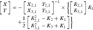
with

where

The receiver consists of a low-noise amplifier and a square law detector. Time management may be carried out by a commercially off-the-shelf dedicated DSP usually used in telecommunication protocol. This operating way is really suited for networks involving a very light infrastructure and a high density of mobile stations. The calculation for its TDOA(τ) assumes the knowledge of the I–Q data. In the case of monochromatic source (δF = 0) and assuming only line-of-sight (LOS) propagation, I and Q signals are pure sinusoidal functions of period 1/τ.
Schematic diagram of the transceiver.

I signal versus frequency for the two extreme TDOA.

C) Multipath consideration
Due to multipath propagation, direct inversion is no longer possible because the analytical received signal S(f) differs from the simple sinusoid form of I–Q and is now expressed as follows:

where E i is the signal amplitude linked to paths i, τ LOS is the useful TDOA associated with the paths' length difference between direct paths 1 and 2, τ NLOS1k is the TDOA associated with paths' length difference between the LOS path 1 and the whole possible paths k assuming k is an odd integer superior to 2. τ NLOSi2 is the TDOA associated with the paths' length difference between LOS path 2 and the whole possible path i, assuming i is an even integer superior to 1. And finally τ NLOSij is the TDOA associated with the paths' length difference between the whole possible combinations of NLOS paths i and k assuming i ≠ 1 and k ≠ 2.
Due to the attenuation of propagation and possible reflection losses, the fourth term in the previous expression, weighted by E iE k (with i even and superior to 1, and k odd and superior to 2), is a second-order one and can be neglected. This hypothesis is particularly observed whenever circularly polarized antennas are used. Considering a ray propagation model and the celerity c, τ LOS is comprised between −B/c and B/c and then the first term of the above generic form describes a period when the frequency spreads as a bandwidth ΔF = c/B. In the opposite the TDOA τ NLOS1k and τ NLOSi2 are very large in comparison with τ LOS and then the second and third terms of this equation vary extremely rapidly with the frequency.
Otherwise a narrow random sweep δF in transmitter frequency (typically δF > 500 MHz as defined for UWB communications) gives an averaged signal S(f) where the second and third terms are mitigated. NLOS TDOA are defined as the channel differential time coherency and contribute to determine the bandwidth of the filters. They also characterize the channel in terms of coherency bandwidth. The LOS contribution is separated from NLOS one by performing either an analog or digital sliding average of S(f). The resulting signal (real part I for example) is slightly the same than the signal shown in Fig. 3. Actually, due to the modulation with a “sinc” function, the argument of which is πδFτ, the amplitude of the sinusoid associated with the maximum TDOA is slightly less than the function associated with the null TDOA.
D) Enhanced-TDOA measurements
Targeting the location process, one must perform high accuracy time measurement and especially enhanced TDOA measurement. We first determine the response of channel with a method more compatible with TDOA-based applications. Usually, the channel is characterized by determining the impulse response given by the Fourier transform of the frequency response. We proceed in a different way more compatible with the localization algorithm because it considers a differential impulse response in the TDOA domain. The enhanced TDOA measurement uses an algorithm based on the least mean squares, which allows isolating the waveform I only due to the LOS path and thus eliminates the influence of the multipath contribution. Considering equation (4) in the TDOA domain, it only remains that the delay is related to LOS. This method compares the signal I detected with an ideal signal I whose time period and phase are tuned:

When the signal is close to the proposed signal, the error ε can be expressed by equation (5) is near zero and then, the resulting period is directly related to the required TDOA:

For a given environmental setup corresponding to a large furnished room (7 m × 5.5 m), the determination of the differential impulse response from the Fourier transform of the measured signal S(f) exhibits, in Fig. 4, both the useful LOS contribution and parasitic NLOS one. Using the dual transmitter described in Fig. 2 and assuming a very simplified microwave receiver associated with a suitable DSP unit, the corrected channel response is as shown in Fig. 5 using the enhanced TDOA algorithm described previously. We see that the multipaths are now drastically mitigated and we measure only the LOS TDOA contribution. Assuming this enhanced TDOA measurement, one can now perform the localization process or other TDOA-based applications.
Differential impulse response measured between 57.5 and 59 GHz.

Corrected differential impulse response.

E) Location error
Following the correction of the differential impulse response described previously, the estimated position of the transmitter by different mobile stations can be determined. We have considered significant parameters such as the radial distance and the baseline to perform the different enhanced TDOA calculation based on the collected experimental results. The comparison between the estimated position and the real one provides the performance of the developed system in terms of location error. Figure 6 shows the impact of the baseline value on the location error. We note that the location error decreases significantly when the baseline value growths. The trade-off between the location accuracy and the system sizes is well described by such results: a baseline value equal to 5 cm is sufficient to ensure an error location in the range of 5 cm. To reach a location error lower than 2 cm, a baseline value rather than 10 cm is required.
Location error (m) versus baseline (m) radial distance = 1.5 m.

Considering a baseline value of 10 cm, Fig. 7 shows the variation in the location error as a function of the radial distance. These experimental results show that the location accuracy is greater than 8 cm for radial distance up to 5 m and by the way validate the performance of this frequency hopping 60 GHz location system.
Location error (m) versus radial distance (m) baseline = 0.1 m.

It is worth noting that the delay spread of the tested radio channel is between the value of 1.7 and 8.1 ns, depending essentially on the radial distance. Hence, the performance of this system still needs to be verified with more severe multipath conditions.
F) Conclusion
In the first part, we have achieved and experimentally validated the performance of a location system exploiting high data rate multi-carrier signals originally dedicated to radio communications. We have demonstrated the impact of the multipath propagation using such a topology and a way to prevent the location error from degradation due to the multipath influence described previously.
III. SIXTY GIGAHERTZ IMPULSE UWB LOCATION SYSTEM
In this part, we report the performance of a positioning 60 GHz system operating in an indoor environment by exploiting impulse radio UWB (IR-UWB) signals. The main original contribution is an approach based on a passive time reversal (TR) processing developed in a single input multiple output (SIMO) configuration. Experimental results validate the ability of the topology to perform TDOA of 60 GHz sub-nanosecond impulse signals without global synchronization. The TR technique is introduced and its impact on the location accuracy is presented and validated by numerous experimental results.
A) Topology and experimental setup
Assuming that the radio channel resources are managed by the medium access control protocols, the strategy of the source positioning requires three sensors and the overall topology is described by Fig. 8: the incoming sensor emits IR-UWB pulses streams at 60 GHz that are collected by three selected sensors. Among these sensors, only one of them repeats the incoming signals toward the other sensors according to a predefined scenario composed by three steps: each of the three sensors plays successively the rule of repeater to cancel all the ambiguities due to the lack of synchronization. During each step, all of the three sensors operate by pairs to perform TDOA positioning processing without need of synchronization, providing by the way the possible geometric positions of the source along a hyperbola. Two different TDOA measurements are needed to estimate the source position. Thus, a system of two hyperbola equations must be solved to obtain the estimated position of the source. The three receivers are distributed in two pairs with a common sensor and two sensors within a pair are distant from a baseline equal to B. The topology of the overall transceiver used to determinate one TDOA involves one 60 GHz emitter and three 60 GHz sensors to determinate two hyperbolas (Fig. 9).
Scenario illustration.

Synoptic of passive TR applied to the TDOA location system.

Both the emitters and the receivers have been realized using an MMIC technology [Reference Deparis7]. The pulse generator mainly consists of a high-speed NOR logic gate associated with a varactor diode enabling one to adjust the pulse bandwidth. These pulses are frequency up-converted using a sub-harmonic mixer associated with a 30 GHz free running VCO. The resulting pulse stream up-converted to 60 GHz is then amplified with the use of a medium power amplifier that delivers a peak power equal to 10 dBm. The patch antennas have a half-power beamwidth equal to 60°. The receiver topology of sensors is based on a conventional architecture including a low-noise amplifier, a down-converter associated with a near-60 GHz VCO. The noise figure of the receiver is equal to 6 dB. The resulting IF signal is filtered and amplified before performing a quadratic detection. The recovered pulse can then be re-emitted (or not) according to the fact the repeater functionality is enabled (or disabled) by the MAC layer. Then, each of the two sensors having this functionality disabled performs one TDOA measurement.
The location processing described previously is experimentally tested in a confined environment. Once again, the experimental setup corresponds to a large furnished room (7 m × 5.5 m). In order to validate the performance of the overall system with a statistic approach, we have considered a vast amount of positions sensors inside this room. More than 5000 positions have been taken into consideration for the channel and TDOA measurements
B) Theory of passive TR
The TR, originally used in acoustics, has given rise to many works including those of Professor Mathias Fink, pioneer of these developments. After developing various solutions focusing in the field of ultrasound with mirrors [Reference Fink, Prada, Wu and Cassereau9], his work has led to solutions in radio frequency. Recently, a theoretical study that deals with the impact of the TR on the multiple input multiple output RADAR has been reported [Reference Jin, Moura and O'Donoughue10]. The positioning system we present is based on an SIMO approach associated with a passive TR algorithm: the received signal of the ith sensor is r i(t) = s(t) × h i(t) + n i(t), where h i(t) is the channel impulse response between the source and the ith sensor. The passive TR systems convolve each of these ith received signal by the corresponding time-reversed channel impulse response h i × (−t) before summation. By the way, the resulting signal can be expressed as follows:

Assuming that the knowledge of the channel requires being updated every tenth of seconds, the TR processing is composed of two steps: the first one is to determine each CIR h i(t) for each receiver. These CIRs correspond to the signals resulting from the pulses transmission at the receiver's outputs. The second step consists in convolving each signal r i(t) by the corresponding time-reversed CIR h i*(−t). Finally, all the contributions r i(t) × h i*(−t) are summed before applying the method of Chan [Reference Chan and Ho8] to estimate the source position.
C) Performance of the TR positioning system
The objective is to determinate experimentally the enhancement of the location accuracy by using the TR processing. In order to tend toward statistic experimental results, we have performed a large amount of channel impulse response measurements (>5000). Considering the experimental setup described previously, the positioning system is tested and the impact of critical parameters such as the radial distance and the baseline on the system performance are taken into account.
1) Influence of the baseline B
The baseline corresponds here to the distance between two sensors involved in the calculation of one TDOA. Assuming that the sensors are organized in pair having the same baseline value, we calculate the estimated positions of the source with and without applying the TR processing.
Figure 10 exhibits the evolution of the error as a function of a baseline. These experimental results show the well-known dilution of precision in TDOA when the baseline is not sufficient. Nevertheless, these results clearly demonstrate the significant enhancement due to the TR processing since a reduction of the error in the range of 14% which can be observed for most of the baseline values.
Location error (m) versus baseline (m).

2) Influence of the radial distance
Further measurements have been led to determinate the error of location as a function of the radial distance. We compare the estimated positions with and without TR. Considering a baseline equal to 80 cm both for each pair of sensors, Fig. 11 shows the accuracy is degraded when the radial distance increases: the impact of the SNR on the error is well verified as described by the Kramer–Rao lower band [Reference Benlarbi-Delaï and Cousin6]. Such an impact of the SNR is either verified when the TR processing is applied.
Location error (m) versus radial distance (m).

These experimental results show that the TR processing enhances significantly the performance of the 60 GHz positioning system. We note a mean improvement in the range of 16%.
3) Frequency distribution of errors with and without TR
Considering all the measurements we have performed in the large furnished room depicted by Fig. 12, we have calculated the location errors for all baseline and radial distance values. In order to clearly summarize them, Fig. 13 exhibits the frequency distributions of location errors with and without TR. These ones show that most of the errors are focused below the value of 35 cm when the TR processing is considered instead of 45 cm in the other case (considering a threshold equal to 1%). These frequency distributions enable to conclude to an enhancement of the accuracy in the range of 22% and validate by the way the concept of TR applied to the positioning systems.
Photography of the environmental setup.

Frequency distributions of the location errors.

Once again, it is worth noting that the delay spread of the tested radio channel is between the value of 3.2 and 8.3 ns, depending essentially on the radial distance. Hence, the performance of this system still needs to be verified with more severe multipath conditions.
IV. CONCLUSION
In this paper, we have presented both frequency hopping and impulse topologies dedicated to 60 GHz location systems. For each topology, a specific signal processing has been considered to reduce significantly the impact of the multipath propagation due to confined environments. The experimental results validate the performance of each system and it is worth noting that these two topologies are well suited to perform data transmission. We conclude that the frequency hopping topology is specific to the deterministic networks using frequency division multiple access or time division multiple access. On the other hand, the impulse location system is the most appropriate solution for a statistic network using a carrier sense multiple access with collision avoidance multi-user strategy.
ACKNOWLEDGEMENTS
This work was supported by the European Regional Development Fund and by the Nord-Pas-de-Calais Region.
 Michael Bocquet studied electronics engineering and telecommunications at the University of Sciences and Technologies from Lille (France). He received his Ph.D. degree in 2007. He worked at INRETS as a radio engineer in 2008. Since 2009, he joined the Institute of Electronic Microelectronic and Nanotechnology where he is now an assistant professor. His main research activities are RF transceivers for telecommunication and localization systems operating in millimeter-wave frequency bands.
 Christophe Loyez studied electronics engineering and telecommunications at the University of Sciences and Technologies Lille 1, France. He received his Ph.D. degree in electronics engineering in December 2000 at the IEMN. He worked at Alcatel as a radio engineer in 2001. Since 2002, he joined the CNRS and is now a researcher at the Institute of Electronic Microelectronic and Nanotechnology (IEMN) – UMR CNRS 8520 – near Lille (France). His main research activities are radio over fiber systems, RF transceivers for telecommunication, and localization operating in millimeter-wave frequency bands.
 Nathalie Rolland received his engineer degree in microelectronics from the Polytech'Lille, Villeneuve d'Ascq, France, in 1986, and Ph.D. degree in electronics from the University of Lille 1 in 1989. She is currently a Professor with the IEMN. From 1989 to 2000, she investigated quasi-optical approaches and 3-D interconnects for millimeter-wave devices, circuits, and subsystems for communication application. Since 2000, she has been mainly involved in the field of advanced communication systems for smart object communication and sensors networks in the millimeter-wave range. She possesses lengthy experience in circuits and subsystems design, assembly, and characterization.



