
1. Introduction
Whenever acceleration is imposed on a fluid flow either by a body acceleration or by an external acceleration imposed on the fluid, additional fluid forces will act on the surface contact with the fluid (Brennen Reference Brennen1982). These fluid inertial forces can be of considerable importance in many dams and hydropower and water/ocean engineering problems; furthermore, it has an important effect on the dynamics of a vibrating structure, particularly in its natural frequencies and damping characteristics.
This hydrodynamic force should be calculated via three-dimensional Navier–Stokes equations, however, this is a difficult task, even in simple cases. In many practical situations, the effects of fluid viscosity and compressibility on the hydrodynamic mass can be neglected. In these cases, incompressible potential flow theory can be used to calculate the added mass (e.g. Chung & Chen Reference Chung and Chen1984).
The presence of a solid boundary can cause a substantial increase in added mass. This is due to the necessary increase in the fluid accelerations, primarily in the region between the fluid and the boundary (Brennen Reference Brennen1982; Reference Brennen2006). Chung and Chen (Reference Chung and Chen1984) provided formulae and graphs for computing the added mass for an eccentric cylinder near a wall. The results of this study showed an increase of added mass when the gap between the body and the wall decreases. For example, the added mass of a circular cylinder with radius r increases by a factor of r 2/2 $\varDelta$2, where
 $\varDelta$ is the wall distance measured from the centre of the cylinder. Consequently, when the body is very close to the wall, the added mass increases at an even greater rate. This is because, within a thin fluid film or narrow gap between the body and the wall, the fluid acceleration can be very large indeed.
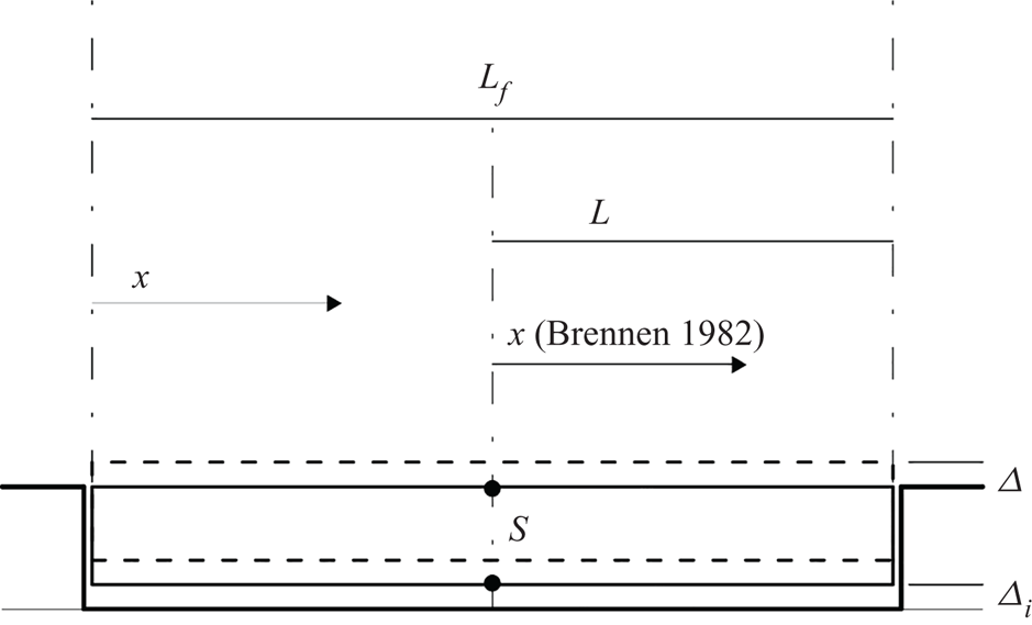
From a practical engineering point of view, there is a scarcity of data for this extreme condition, close to the proximity of a body to the wall. Brennen (Reference Brennen1982) considered the two-dimensional problem of a flat plate with width Lf lying on the ocean floor (figure 1). A vertical upward force, F, per unit of length of the plate is applied at the centre of the plate to lift it away from the floor. Due to this force, the plate rises to a uniform height  $\varDelta$(t) above the floor at time t. The fluid is assumed incompressible. The upward velocity of the plate, dΔ/dt, generates a large horizontal velocity, v, in the gap between the plate and the wall according to the mass balance equation,
 $\Delta v ={-} x\,\textrm{d}\varDelta /\textrm{d}t$. Here the abscissa x starts from the centre of the plate (figure 1). The momentum equation, in the absence of frictional or viscous force, yields to
 $(1/\rho )(\partial p/\partial x) + 2v(\partial v/\partial x) + (1/\varDelta )(\partial (\Delta v)/\partial t) \!=\! 0$. Coupling and integrating momentum and mass balance equations, one obtains the pressure distribution, p(x,t), in the fluid gap and, consequently, the added mass force
 $F = {\textstyle{2 \over 3}}\rho ({L^3}/\varDelta )[{\partial ^2}\varDelta /\partial {t^2} - (2/\varDelta ){(\partial \varDelta /\partial t)^2}]$, where ρ is water density, and L = Lf/2. For this case, the literature tabled formula is simplified in
 $F = {\textstyle{2 \over 3}}\rho ({L^3}/\varDelta )[{\partial ^2}\varDelta /\partial {t^2}]$ (Chung & Chen Reference Chung and Chen1984). Comparing this formula with the known tabled formula on the plate in an infinite domain,
 $F = \rho {\rm \pi}{L^2}{\partial ^2}\varDelta /\partial {t^2}$, the near-bottom effect increases the added mass force, F. The added mass force practically represents the near-bottom force, Fu, by a factor of L/
 $\varDelta$ when L approaches
 $\varDelta$.
Sketch of near-bottom flat plate/slab problem, according to Brennen (Reference Brennen1982, Reference Brennen2006). Here  $\varDelta_i$ is the initial gap thickness between the body and the wall,
 $\varDelta$ is the instantaneous change of the gap thickness and S is the body thickness. The initial location of the body is shown by solid line and the location of the body after displacement is shown by dashed lines.

In the above analysis, fluid incompressibility was assumed. The real fluid is compressible, and the compressibility could be of some importance, decreasing the ratio  $\varDelta$/L. This is expected from a physical point of view because the fluid compressibility acts as a spring with stiffness, K, for units of length in the near-bottom force that is
 $Fu = K2L\varDelta $ according to Hooke's law of linear elasticity (Ugural & Fenster Reference Ugural and Fenster2003). The effect of fluid compressibility was experimentally evidenced by Federspiel (Reference Federspiel2011) and Duarte, Pinheiro & Schleiss (Reference Duarte, Pinheiro and Schleiss2016) in a quasi-prototype scale experimental model of a high-velocity jet impacting a plunge pool. A cubic aluminium block with the side of 200 mm was inserted into a box, 201 mm deep and 202 mm wide, of the same material at the plunge pool bottom. As a consequence, a thin water film of 1 mm in thickness was present under the cubic block. This cubic block was instrumented with displacement and acceleration transducers.
Duarte et al. (Reference Duarte, Pinheiro and Schleiss2016), using theoretical analyses, pointed out that the near-bottom force for a flat plate is  $Fu = K2L(\ln \varDelta + B)$, where B is a constant. However, the experimental evidence (Duarte et al. Reference Duarte, Pinheiro and Schleiss2016) showed that the near-bottom force is
 $Fu = K2L(\varDelta + B)$ according to Hooke's law of linear elasticity, which is expected from a physical point of view because the fluid compressibility is assumed as a spring in the near-bottom fluid layer.
The above theoretical considerations by Duarte et al. (Reference Duarte, Pinheiro and Schleiss2016) were developed in a Heuristic way without any analysis of the fluid motion inside the thin fluid layer (i.e. 1 mm thin fluid at the bottom) due to its changes in thickness in time caused by the movement of the block. Thus, these theoretical considerations do not fully explain the physical phenomena, and in particular, the strong block accelerations measured by Federspiel (Reference Federspiel2011).
No comprehensive analysis of the added mass effect on an immersed body close to a wall was found in the literature. Brennen (Reference Brennen1982, Reference Brennen2006) suggested this as an area deserving further study both experimentally and analytically. This paper presents the dynamic analysis of a fairly flat object lying on the ocean floor. This is similar to the case of a free block embedded into an impermeable cavity, filling with fluid, where experimental studies on dam plunge pools are available (Federspiel Reference Federspiel2011). The first objective of this paper is to study the compressible flow inside a moving thin fluid thickness to define the instantaneous pressure field, and via integration, the force, Fu, acting on a body. Then, coupling these hydrodynamic equations with the block Newton's law equation, the body displacement subject to an external force is computed.
In this paper, taking into account the fluid compressibility, quite different outcomes concerning the near-bottom added mass are derived, compared with the studies in the literature that are based on the incompressible fluid. These new outcomes highlight the presence of high-frequency fluctuating components in Fu, able to produce strong body accelerations that were experimentally measured by Federspiel (Reference Federspiel2011).
The fluid compressibility prevents the possibility to obtain closed formulae or graphs in the near-bottom analysis, similar to those achieved via added mass theory. This is expected because the added mass phenomenon is stringently due to the low pressure generated beneath the body, due to the expansion of the fluid. In the literature (e.g. Chung & Chen Reference Chung and Chen1984), added mass was computed via incompressible potential flow theory. These computations were extended to the cases when a body approaches a wall, even if the physical phenomenon is quite different. These differences are investigated in this study, however, the term ‘added mass’ is used in this paper for historical reasons being congruent with the literature.
The paper is organised as follows: in § 1, the theoretical analysis of added mass near-bottom effects, based on compressible fluid concept, is drawn out; in § 2, a new set of equations is applied to an immersed body, subject to an instantaneous upward displacement and a periodic oscillation displacement, to compute the near-bottom force; in § 3, the body displacement subject to a constant upward force is analysed; and in § 4, the obtained results are discussed. A set of conclusions, highlighting the importance and novelty of this paper, are reported at the end.
2. Near-bottom immersed body motion: theoretical analysis of compressible fluid
Mathematical modelling of a body motion in the proximity of a solid boundary requires considerations of both compressible fluid motions in the gap between the body and the wall, and body force balance (figure 1).
The flow field inside the gap between the body and the wall (figure 1) due to the body displacement is analysed via mass balance and momentum equations taking into account the instantaneous change of the gap thickness,  $\varDelta$, in time. The length Lf is assumed larger than the body thickness, S, according to Brennen (Reference Brennen1982). In the following equations the abscissa, x, starts from left side of the plate (figure 1).
2.1. Mass balance equation
The net mass inflow–outflow per unit of time and unit of width into the infinitesimal space length,  ${\delta _s}$ (left-hand side term of (2.1)) must be equal to the mass changes per unit of time, that is
 $[{(\rho \mathrm{\Delta }V)_{x}}\ {\delta _s}] = {(\rho \varDelta{\delta _s})_t}$. Here, V is the instantaneous fluid velocity,
 ${\delta _s}$ is the selected space length (i.e. infinitesimal space length) and the subscripts x and t indicate partial differentiation. The body displacement happens in the vertical direction without rotation (figure 1); thus, it is
 $\varDelta_x$ = 0. In this context, one obtains
 \begin{equation}\frac{{\dot{\rho }}}{\rho }\varDelta + {\varDelta _t} + \Delta {V_x} = 0,\end{equation}
where the dot over a variable indicates the total derivative in time.
The first term of (2.1) accounts for the liquid compressibility, the second term for the change in the fluid gap thickness and the third term for the changes between inflow and outflow mass at an instant. Because it is  $\dot{\rho }/\rho = \dot{p}/K$, where K is the bulk modulus of elasticity of the fluid, by defining the pressure celerity, a, as
 $a = \sqrt {K/\rho } $ (Streeter & Wyle Reference Streeter and Wyle1967), equation (2.1) becomes
 \begin{equation}{V_x} + \frac{{g\dot{H}}}{{{a^2}}} + \frac{{{\varDelta _t}}}{\varDelta } = 0,\end{equation}
where H is the instantaneous piezometric head, and g is the acceleration of gravity.
In the experiments of Federspiel (Reference Federspiel2011) and Duarte et al. (Reference Duarte, Pinheiro and Schleiss2016), in a quasi-prototype scale model of a high-velocity jet impacting a plunge pool, in the small fluid gap between the body and the plunge pool bottom (i.e. 1 mm), a pressure celerity a = 100 m s−1 was estimated. This value of celerity accounts for the existence of air bubbles inside the water gap that makes the fluid more compressible. This value of celerity is used hereafter in the numerical examples.
2.2. Momentum equation
The forces acting at the boundary of the selected space, δs, of a horizontal gap between the body and the wall are (Streeter & Wyle Reference Streeter and Wyle1967): (i) the difference in the pressure force acting on the fluid gap area at downstream and upstream sections of the selected space; and (ii) the frictional wall shear stress. Detailing these two items, dropping the higher-order terms, one obtains  $- {(p\varDelta )_x}\,{\delta _{s}} - \,\tau (\varDelta /{R_H})\,{\delta _s} = \rho V{\varDelta _t}{\delta _{s}} + \rho \varDelta{\delta _s}\dot{V}$, where
 $\tau $ is the shear stress,
 $\dot{V}$ is the velocity total derivative with respect to time and
 ${R_H}$ is the hydraulic radius of the gap. The left-hand side term of this equation must be equal to the change of momentum shown on the right-hand side term; here, the term
 $\rho V{\varDelta _t}{\delta _{s}}$ takes into account the change in the fluid mass due to the block/slab movement,
 $\varDelta$, in time. Simplifying and dividing the equation above by the fluid mass,
 $\rho \varDelta {\delta _s}$, and having
 ${p_{x}} = \rho g{H_x}$ and
 $\varDelta_x$ = 0, one obtains
 \begin{equation}g{H_x} + {k_{f}}\ V|V|+ \frac{V}{\varDelta }{\varDelta _t} + \dot{V} = 0,\end{equation}
where
 \begin{equation}\tau \frac{\varDelta }{{{R_H}}}\frac{{{\delta _s}}}{{\rho \varDelta {\delta _s}}} = \gamma {R_H}J\frac{\varDelta }{{{R_H}}}\frac{{{\delta _s}}}{{\rho \varDelta {\delta _s}}} = gJ = {k_{f}}\ V|V|,\end{equation}
with  $J$ the energy slope,
 $\gamma $ the specific weight of the fluid and kf the friction factor, which depends on the gap thickness,
 $\varDelta$.
The effects of the nonlinear terms in the mass balance equation (2.2) and the momentum equation (2.3) were analysed by Fiorotto & Rinaldo (Reference Fiorotto and Rinaldo1989) and Ghidaoui et al. (Reference Ghidaoui, Zhao, McInnis and Axworthy2005). Fiorotto and Rinaldo (Reference Fiorotto and Rinaldo1989), via perturbation analysis, highlighted that the effect of the second-order terms on the water hammer solution in a thin water film is of the order of O(10−3). The same conclusion was reached by Ghidaoui et al. (Reference Ghidaoui, Zhao, McInnis and Axworthy2005) via dimensionless analysis because the second-order terms are weighed by the Mach number, M = V/a. Here, V is of the order of O(1 m s−1), whereas a is in the range 100–1000 m s−1; so that M is in the range 0.01–0.001. The two approaches give similar results highlighting that the nonlinear terms can be neglected in the water hammer equations.
2.3. Characteristic equations
Neglecting the nonlinear terms in (2.2) and (2.3), the characteristic equations method (Streeter & Wyle Reference Streeter and Wyle1967) gives the following two pairs of equations identified as C + and C −:
 \begin{gather}\frac{g}{a}\frac{{\textrm{d}H}}{{\textrm{d}t}} + \frac{{\textrm{d}V}}{{\textrm{d}t}} + {k_f}V|V|+ \frac{V}{\varDelta }\frac{{\textrm{d}\varDelta }}{{\textrm{d}t}} + \frac{a}{\varDelta }\frac{{\textrm{d}\varDelta }}{{\textrm{d}t}} = 0\quad \textrm{and}\quad \frac{{\textrm{d}x}}{{\textrm{d}t}} ={+} a\quad ({C^ + }),\end{gather}
 \begin{gather}- \frac{g}{a}\frac{{\textrm{d}H}}{{\textrm{d}t}} + \frac{{\textrm{d}V}}{{\textrm{d}t}} + {k_f}V|V|+ \frac{V}{\varDelta }\frac{{\textrm{d}\varDelta }}{{\textrm{d}t}} - \frac{a}{\varDelta }\frac{{\textrm{d}\varDelta }}{{\textrm{d}t}} = 0\quad \textrm{and}\quad \frac{{\textrm{d}x}}{{\textrm{d}t}} ={-} a\quad ({C^ - }).\end{gather}
Because  $a \gg V$, it is
 $(a/\varDelta )(\textrm{d}\varDelta /\textrm{d}t) \gg (V/\varDelta )(\textrm{d}\varDelta /\textrm{d}t)$, so that the latter term can be neglected.
2.4. Numerical solution of uplift force
The characteristic equations (2.5) and (2.6) are discretised and solved in a computation grid with steps Dx = Lf/N and Dt = Dx/a; hence,  ${\delta _s} = {\rm D}x = a{\rm D}t$, imposing the boundary conditions at the gap between the body and the wall ends equal to the known piezometric head, H (figure 1). To satisfy this boundary condition at the gap right side end, the discretised C + characteristic lines (2.5) must be used, that is,
 \begin{equation}{V_p} = {V_R} - \frac{g}{a}({H_P} - {H_R}) - \frac{a}{\varDelta }\textrm{d}\varDelta - {k_f}{V_R}|{V_R}|{\rm D}t,\end{equation}
whereas at the left side end, the discretised C − characteristic lines (2.6) must be used, that is,
 \begin{equation}{V_T} = {V_S} + \,\frac{g}{a}({H_T} - {H_s}) + \frac{a}{\varDelta }\textrm{d}\varDelta - {k_f}{V_R}|{V_R}|{\rm D}t.\end{equation}
The variable  $\textrm{d}\varDelta $ is the change in the gap thickness in the interval time, Dt.
Solving (2.5)–(2.8), the piezometric head, H, along the gap between the body and the wall is computed, imposing the boundary conditions at the gap ends that is the known piezometric head. The near-bottom body uplift force, Fu, is hence
 \begin{equation}{F_u} = \gamma \int_0^{{L_f}} {H\,\textrm{d}x} .\end{equation}
3. Movement of an immersed body: near-bottom force analysis
The added mass near-bottom effect is here analysed according to Brennen (Reference Brennen1982, Reference Brennen2006), where a fairly flat body lying on the ocean floor (figure 1) was considered. In this case, one has the same piezometric head at the near-bottom thin fluid layer ends and, here, the initial flow velocity is equal to zero. When the body has a small movement, an instantaneous change in the gap thickness,  $\textrm{d}\varDelta $, occurs. This displacement, with an initial fluid velocity in the fluid gap equal to zero, causes a change in the piezometric head, dH, constant along the gap length ((2.5) and (2.6)), which is
 \begin{equation}\textrm{d}H ={-} \frac{{{a^2}}}{g}\frac{{\textrm{d}\varDelta }}{\varDelta }.\end{equation}
Equation (3.1) highlights that the change in the piezometric head depends on the relative change in the fluid gap thickness,  $\textrm{d}\varDelta /\varDelta $. This result is consistent from a physical point of view. The instantaneous increment of the fluid gap thickness causes an expansion of the fluid, which results in a decrease in the pressure head, whereas a decrement in the fluid gap thickness causes compression of the fluid inside the gap, giving an increment of the fluid pressure head. From a physical point of view, due to the elastic behaviour of the fluid, the change in the pressure to obtain a fluid deformation must depend on the variation of the relative fluid volume. Increasing the time, a movement of the fluid happens, starting from the end sections of the gap, due to the unbalance of the pressure boundaries.
The fluid velocity, V, at the fluid gap end section can be computed via (2.7) or (2.8), hence,
 \begin{equation}|V|= a\frac{\textrm{d}\varDelta}{\varDelta},\end{equation}
When the flow velocity,  $|V|$, changes in a fluid gap section, the piezometric head changes, which is
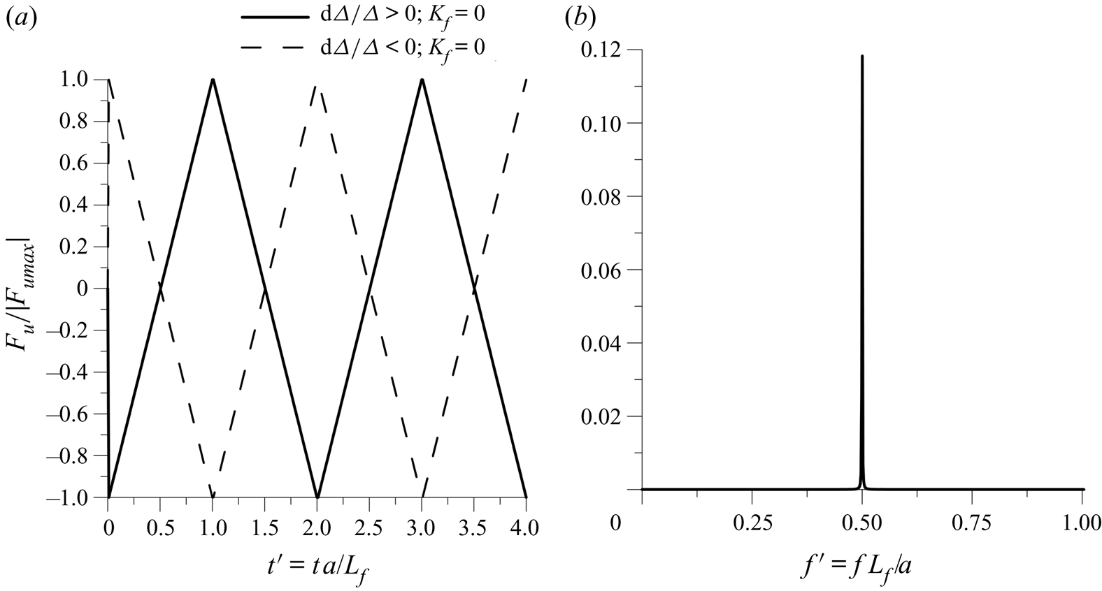
 $dH ={-} ({a^2}/g)(\textrm{d}\varDelta /\varDelta ) ={-} (a/g)|V|$ (see (3.1) and (3.2)). This means that, starting from both gap ends, the pressure waves generated by the imposed boundary pressure progressively change the fluid pressure inside the fluid gap. The two pressure waves, starting from the fluid gap ends, reach the middle of the gap length, Lf/2, at t = 0.5Lf/a. Here the fluid velocity is equal to zero because the two flows coming from the two gap ends have opposite directions and, consequently, it is
 \begin{equation}dH = \frac{{aV}}{g} ={-} \frac{{{a^2}}}{g}\frac{{\textrm{d}\varDelta }}{\varDelta }.\end{equation}
The pressure wave reaches the gap end at t = Lf/a producing, in this instant, the maximum uplift force equal to  ${F_{umax}} = \gamma \int_0^{{L_f}} {H\,\textrm{d}x} = \gamma ({a^2}/g)|\textrm{d}\varDelta /\varDelta |{L_f}$. The minimum uplift force,
 ${F_{umin}}$, occurred at t = 0, is equal to
 ${F_{umin}} = \gamma \int_0^{{L_f}} {H\,\textrm{d}x} ={-} \gamma ({a^2}/g)|\textrm{d}\varDelta /\varDelta |{L_f}$ . This process is repeated in time, as shown in figure 2, computed via integration of (2.5), (2.6) and (2.9). The force
 ${F_u} = K\,\textrm{d}\varDelta $ can be considered as the outcome of springs with stiffness, K, equal to
 $\gamma ({a^2}/g\varDelta ){L_f}$, with spectral components close to the natural dimensionless frequency,
 ${f^{\prime}_c} = f{L_f}/a = 0.5$.
(a) Behaviour of the dimensionless force,  ${F_u}/|{F_{umax}}|$, on the dimensionless time,
 $t^{\prime}$ = ta/Lf; and (b) spectral component of the dimensionless force,
 ${F_u}/|{F_{umax}}|$, on the dimensionless frequency,
 $f^{\prime}{=}\,\,fL_{f}/a$.

A generic body displacement is computed as a sequence of instantaneous infinitesimal body displacements,  $\textrm{d}\varDelta $, at interval time, Dt, according to (2.7) and (2.8). The force, Fu, computed via (2.9), acting on a near-bottom immersed body in the case of an imposed oscillating body motion with frequency, f, is shown in figure 3. This topic is common in the structural vibration analysis for ships, heat exchangers, aerospace and civil engineering, etc. For example, in civil engineering, it happens in sealed concrete slabs in hydraulic jump stilling basins or plunge pools downstream of large dams and hydropower outlets, where strong fluctuating pressures acting over the slabs modify the thin water film thickness under the slabs (Barjastehmaleki, Fiorotto & Caroni Reference Barjastehmaleki, Fiorotto and Caroni2016b; Fiorotto, Barjastehmaleki & Caroni Reference Fiorotto, Barjastehmaleki and Caroni2016; Maleki & Fiorotto Reference Maleki and Fiorotto2019b). The study of the sealed concrete slabs within dissipaters requires the analysis of an oscillating, immersed, fairly flat body close to the bottom. The body motion is assumed equal to
 \begin{equation}\varDelta (t) = {\varDelta _0}(1 + \xi \sin (2{\rm \pi} ft)),\end{equation}
with  ${\varDelta _0}$ the mean fluid thickness in time (m) and
 $\xi $ the dimensionless amplitude.
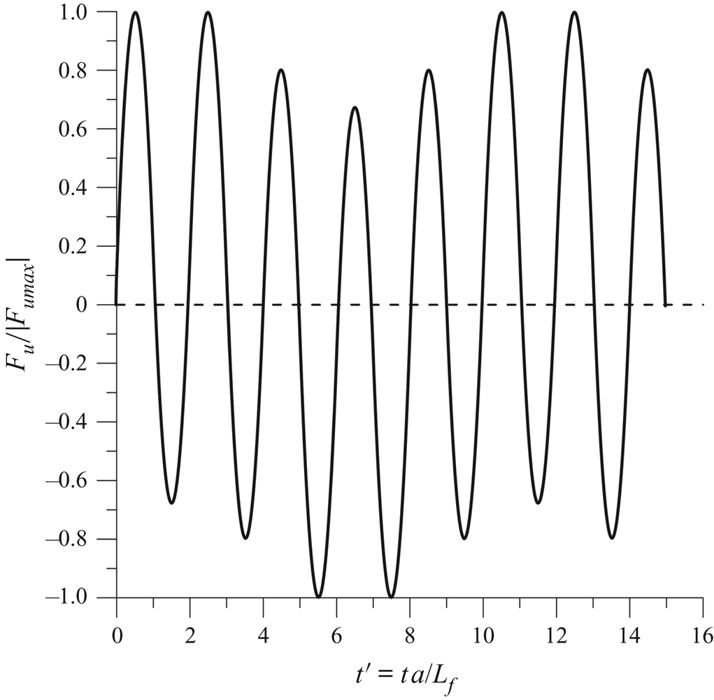
Dimensionless force,  ${F_u}/{F_{umax}}$, versus dimensionless time,
 $t^{\prime}$ = ta/Lf.

Figure 3 shows the time behaviour of the dimensionless fluctuating force,  ${F_u}/{F_{umax}}$, acting on the body due to an infinitesimal fluctuating motion, according to (3.4) with dimensionless amplitude
 $\xi \to 0$. From this figure, one can note that the near-bottom fluctuating force is due to the superposition of more sinusoidal components with different frequencies.
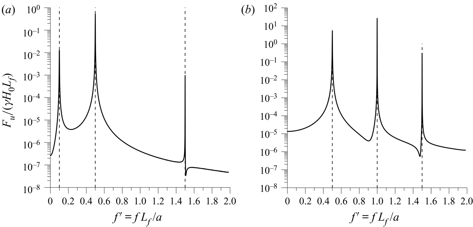
Figure 4 reports the dimensionless spectral components of the ratio  ${F_u}/(\gamma {H_0}{L_f})$ (with
 ${H_0}$ the mean piezometric head), shown in figure 3, for two different dimensionless imposed frequencies,
 $f^{\prime} = f{L_f}/a$.
Spectral component of  ${F_u}/(\gamma {H_0}{L_f})$ for two different dimensionless infinitesimal oscillating frequencies: (a)
 $f^{\prime}$ = fLf/a = 0.1; and (b)
 $f^{\prime}$ = fLf/a = 1. The natural frequencies,
 ${f^{\prime}_c} = 0.5(1 + 2n)$, happen for
 $f^{\prime}$ = 0.5, 1.5, as can be observed in this figure.

The body motion term  $(1/\varDelta )(\textrm{d}\varDelta /\textrm{d}t) = 2{\rm \pi} f\xi\,\cos (2{\rm \pi} ft)/(1 + \xi \sin (2{\rm \pi} ft))$ (see (2.5) and (2.6)) increases when increasing the block motion frequency, f. When the dimensionless amplitude
 $\xi \to 0$, it is
 $(1/\varDelta )(\textrm{d}\varDelta /\textrm{d}t)\sim 2{\rm \pi} f\xi \cos (2{\rm \pi} ft)$.
Comparing figures 4(a) and 4(b), one can note that for  $f^{\prime}$ = 0.1, the spectral components of the force are smaller than the case of
 $f^{\prime}$ = 1. This happens because the block motion term,
 $(1/\varDelta )(\textrm{d}\varDelta /\textrm{d}t)$, increases when increasing the imposed body oscillating frequency. This is well highlighted by the above formula for
 $\xi \to 0$. Spectral component peak happens in
 $f^{\prime}$ and in all the natural frequencies
 ${f^{\prime}_c} = 0.5(1 + 2n)$ with n = 0, 1, 2… (figure 4).
One can note the relevance of the spectral component at frequency  ${f^{\prime}_c}$, especially for the cases of
 $f^{\prime} < {f^{\prime}_c}$ where the spectral component at frequency
 ${f^{\prime}_c}$, with n = 1, is larger than the spectral component at frequency
 $f^{\prime}$.
When the imposed body motion frequency is equal to the natural frequency, a resonance of the system happens, and neglecting the resistance term,  ${F_u}$ tends to infinity. For this reason, the effect of the uplift force at frequency fc could be important, and its effects cannot be neglected a priori in the engineering design.
For large amplitude of the body motion, a spreading of the spectral components on the dimensionless frequency  $f^{\prime}$ occurs due to the nonlinear behaviour of the forced body displacement in time,
 $(1/\varDelta )(\textrm{d}\varDelta /\textrm{d}t) = 2{\rm \pi} f\xi\,\cos (2{\rm \pi} ft)/(1 + \xi\,\textrm{sin}(2{\rm \pi} ft))$.
The near-bottom force (added mass) computed by Brennen (Reference Brennen1982) via incompressible fluid hypothesis is
 \begin{equation}{F_u} = \frac{2}{3}\rho \frac{{{L^3}}}{\varDelta }\left[ {\frac{{{\partial^2}\varDelta }}{{\partial {t^2}}} - \frac{2}{\varDelta }{{\left( {\frac{{\partial \varDelta }}{{\partial t}}} \right)}^2}} \right],\end{equation}
and applying (3.4), in the case of an infinitesimal body oscillation with  $\xi \to 0$, one obtains
 ${F_u} = {\textstyle{2 \over 3}}\rho {L^3}[( - {(2{\rm \pi} f\xi )^2}\sin (2{\rm \pi} ft)\,- 2{(2{\rm \pi} f\xi \cos (2{\rm \pi} ft))^2}]$. One can note that the spectral components at natural frequencies,
 ${f^{\prime}_c}$, are not included in the solution. This highlights the difference between the bottom force spectrum computed via Brennen's formula and that obtained via compressible fluid analysis. From an engineering point of view, this difference in spectra could be important in the structural design because the spectral component at the natural frequency of the system could be larger than the spectral component at frequency f. Furthermore, excluding the spectral components at natural frequencies, the resonance phenomena cannot be pointed out.
The spectra reported in figure 4 is equal to that achieved via Duhamel's principle applied to the wave equations (Fritz Reference Fritz1982) that divides the original problem into two parts: (i) initial problem for the homogeneous wave equation; and (ii) inhomogeneous problem with zero initial condition. The solution of part (i) gives the fluctuating force at the natural frequencies of the system,  ${f^{\prime}_c}$, whereas the solution of part (ii) gives the fluctuating force at the forced frequency
 $f^{\prime}$. From a physical point of view, this is compatible with the results shown in figure 2, where a wave propagation process is manifested. Here the hyperbolic nature of the system of the partial differential (equations (2.2) and (2.3) – wave equation) is pointed out by the two characteristic lines in the real domain (2.5) and (2.6), drawn out from the numerical solution.
4. Force applied on an immersed body: displacement analysis
The body displacement of an immersed embedded block was experimentally studied by Federspiel (Reference Federspiel2011) due to its importance in the dynamic rock block stability in plunge pools downstream of large dams (e.g. Asadollahi et al. Reference Asadollahi, Tonon, Federspiel and Schleiss2011).
Equations (2.5) and (2.6) compute the force acting under the block/slab, taking into account the compressibility of the fluid in the near-bottom thin film, when the displacement,  $\varDelta $, is known. This displacement must be computed via a dynamic analysis based on Newton's law (e.g. Chung & Chen Reference Chung and Chen1984; Barjastehmaleki, Fiorotto & Caroni Reference Barjastehmaleki, Fiorotto and Caroni2016a, Barjastehmaleki et al. Reference Barjastehmaleki, Fiorotto and Caroni2016b), when a force is applied to an immersed body, that is,
 \begin{equation}(m +\, {m_a})\,\frac{{{\textrm{d}^2}\varDelta }}{{\textrm{d}{t^2}}} = {C_e}\frac{{\textrm{d}\varDelta }}{{\textrm{d}t}} + F + {F_u},\end{equation}
where m is the body mass,  ${m_a}$ is the added mass due to the body acceleration acting on the upper surface of the immersed body,
 ${C_e}$ is the equivalent damping of the system, F is the net force acting on the body due to the fluctuating pressure and
 ${F_u}$ is the force due to the near-bottom effects.
Similar to Brennen (Reference Brennen1982), an upward force per the unit of length is applied at the centre of the plate to lift it away from the floor. This movement increases the volume of the fluid under the lower face of the slab, giving, on average, an increment of the ratio  $\textrm{d}\varDelta /\varDelta $. This causes an expansion of the near-bottom fluid that decreases the total pressure acting under the plate giving a negative mean value of Fu. The process is not stationary, because
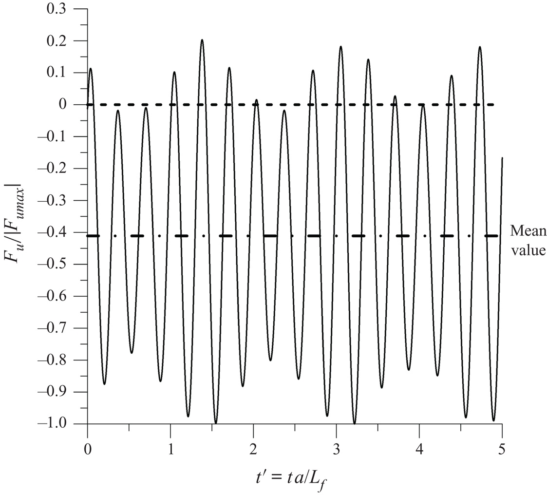
 $\varDelta$ increases in time, so that the process must be analysed by subdividing the total time into small spot time intervals where the quasi-stationarity of the process can be assumed. This is done in figure 5. Obviously, this non-stationarity impedes the spectral analysis of the phenomena globally. For one of these time spots, in figure 5, the dimensionless force Fu/Fumax is plotted on the dimensionless time
 $t^{\prime} = ta/{L_f}$. One can note a remarkable negative value of the mean of Fu due to the fluid expansion in the gap, which is equal to 40 % of its maximum value. This force is against the slab's upward movement, and it outlines the near-bottom added mass effects in the slab dynamic analysis.
Behaviour of Fu/Fumax on the dimensionless time, t′ = ta/Lf. The dotted line, Fu = 0, divides the time interval of fluid expansion (negative values) and fluid compression (positive values).

Figure 5 highlights strong near-bottom force fluctuations larger than its mean value. This force, according to (4.1), generates important high-frequency slab acceleration of the order of  ${a_c} = {F_u}/m$. These strong accelerations of the order of O(10g) have been measured by Federspiel (Reference Federspiel2011) with reference to a cubic aluminium block with a side equal to 200 mm at the bottom of a plunge pool. This block was inserted into a box of the same material containing a cavity that was 201 mm deep, that created an initial thin water film,
 ${\varDelta _i}$, of 1 mm in thickness under the aluminium block. The ratio
 ${\varDelta _i}/{L_f}$ was equal to 0.005.
Some problems were detected in acceleration measurements because the lower limit of the accelerometer was reached in some experiments. Furthermore, the block displacement measurements did not highlight displacement fluctuations congruent with the measured accelerations. The discrepancy between the acceleration and displacement measurements highlights the large frequency in displacements that give the block acceleration. The small block oscillation due to these accelerations are ‘averaged’ in the recorded displacement data because the acquisition rate (1000 Hz) did not respect the Nyquist criteria. This is evidenced in figure 4, where the maximum frequencies of these accelerations are of the order of the natural frequencies of the experimental setup. This can reach a frequency of the order of O(1000 Hz) which is larger than the acquisition rate in Federspiel (Reference Federspiel2011) experiments.
With reference to the strong acceleration values, one must take into account that the relationship between the spectral components of the fluctuating displacement and acceleration, fixing the frequency, f, which is  ${a_{c\omega }} ={-} {\omega ^2}{\varDelta _\omega }$. Here, acω and
 $\varDelta_{\omega}$ are the spectral components of acceleration and displacement, respectively, at the wavenumber ω = 2πf. If the frequency, f, of the fluctuating force,
 ${f^{\prime\prime}_u}$, is of the order of O(1000 Hz), then ω is of the order of O(10 000 rad s−1). This explains the very important accelerations of the order of O(10g) measured in the instrumented block by Federspiel (Reference Federspiel2011) associated with small block fluctuating displacements, because the ratio between the acceleration and displacement is of the order of ω 2, that is, O(108 (rad s−1)2.
Neglecting the equivalent damping of the system, the effects of the near-bottom force on the body displacement can be highlighted by computing the ratio
 \begin{equation}R = \frac{\varDelta }{{{\varDelta ^\ast }}} = \frac{{\iint {(F + {F_u})\,\textrm{d}t\,\textrm{d}t} }}{{\iint {(F)\,\textrm{d}t\,\textrm{d}t} }},\end{equation}
where  ${\varDelta ^\ast } = 0.5(F/(m +\,{m_a})){t^2}$ is the body displacement neglecting the near-bottom effect, that is, the force Fu. The ratio R tends to one increasing the fluid gap between the body and the bottom because the near-bottom effect decreases, increasing the gap fluid thickness,
 $\varDelta$ (see (2.2) and (2.3)). This ratio defines a criterion that highlights the near-bottom effects on the body displacements changing the ratio
 ${L^{\prime}_f} = {\varDelta _i}/{L_f}$.
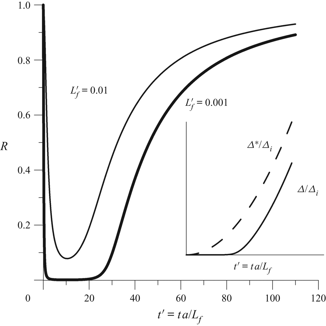
In figure 6, the ratio R is plotted on the dimensionless time,  $t^{\prime}$, applying a net constant upward force, F, on the immersed flat plate. The figure shows the cases of two plates with different length, Lf, with the same initial thin water film thickness. This is shown with
 ${L^{\prime}_f} = {\varDelta _i}/{L_f}$ in figure 6. The ratio between the two plates’ total length is equal to 10. In the same figure, the time behaviour of the dimensionless displacement
 ${\varDelta ^\ast }/{\varDelta _i}$ and
 $\varDelta /{\varDelta _i}$ is reported. From this figure, one can note the relevance of the near-bottom effects on the slab displacement at the initial time, that is for the smaller value of the ratio
 $\varDelta /L_f$.
Near-bottom effects on slab displacement shown by the ratio R versus dimensionless time  $t^{\prime}$.

From figure 6, one can note that the near-bottom effect is very important in the upward body displacement reduction in the first stages where the thin water film thickness is small; this effect, increasing the time, decreases strongly because of the thin water film thickness under the body increases. From (2.2) and (2.3), one can note that, increasing the displacement,  $\varDelta $, the near-bottom effect of added mass reduces as
 $1/\varDelta $ and progressively disappears. When
 $\varDelta \to \infty $, (2.2) and (2.3) become the classical water hammer equation (Streeter & Wyle Reference Streeter and Wyle1967). In this case, when the celerity a → ∞ (incompressible fluid), one obtains the incompressible Euler equations used by Brennen (Reference Brennen1982, Reference Brennen2006) in analysing the near-bottom added mass effect (figure 1) as cited previously. From a physical point of view, this reduction of the near-bottom effect increasing
 $\varDelta $ is due to the elastic behaviour of the fluid. Consequently, the change in the pressure to obtain a fluid deformation depends on the variation of the relative fluid volume that depends on the fluid thickness (3.1). Equation (3.1) sets out the instantaneous small body movement according to Hooke's law (i.e. for small time scale); globally the phenomena (i.e. for large time scale) can be analysed by subdividing the total time into small spot time intervals where the validity of (3.1) can be assumed. The large time scale analysis needs the time integration of (2.5) and (2.6) (figure 6).
The near-bottom effects on the upward slab displacement reduction depend on the ratio  ${L^{\prime}_f} = {\varDelta _i}/{L_f}$, that is, the initial geometric condition of the process; decreasing this ratio, the near-bottom effects become increasingly important.
The fluctuating effects of Fu, shown in figure 5, is not well evident in the body displacement plotted in figure 6 due to its high frequency. This is congruent with the block displacement experimental measurements of Federspiel (Reference Federspiel2011), where the effects of the strong accelerations of the order of O(10g) was not evidenced in the block displacement figures.
It is of some interest in the evaluation of the displacement to analyse the ratio  $\textrm{d}\varDelta /\varDelta $ on the ratio
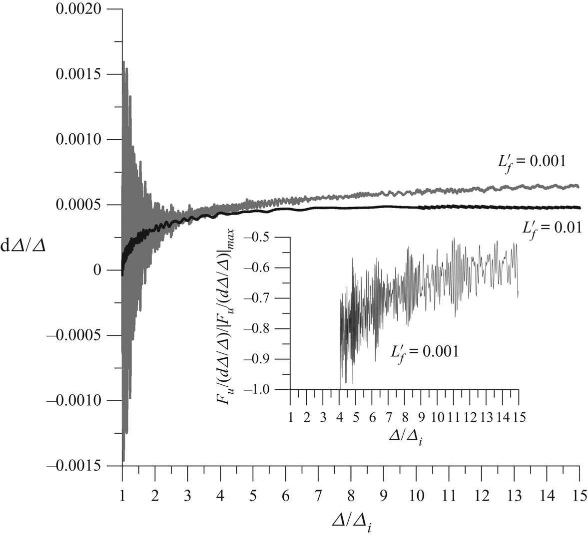
 $\varDelta /{\varDelta _i}$ in the first stages of the upward slab movement; the relationship between these ratios is plotted in figure 7 for the two cases reported in figure 6. From figure 7, one can note some differences in the behaviour of
 $\textrm{d}\varDelta /\varDelta $ changing the slab length in the first stages of the slab movement.
Behaviour of the ratios  $\textrm{d}\varDelta /\varDelta$ and
 ${F_u}\,\varDelta /\textrm{d}\varDelta {L_f}$ dimensionless with its absolute maximum value on the ratio
 $\varDelta /{\varDelta _i}$.

According to the above considerations, the initial movement of the slab causes the instantaneous increment of the gap thickness with an expansion of the fluid, resulting in expansion and compression of pressure waves generation with frequency, f = 0.5a/Lf. These pressure waves, being of opposite sign, cause the oscillation of the body. Increasing the slab length, Lf, the persistent time, tp = Lf/a, of these pressure waves increases, giving a more relevant negative and positive body displacement. This is because, according to Newton's law, the body displacement is a function of the square of the persistent time. This is well evidenced in figure 7 in the range of  $1 < \varDelta /{\varDelta _i} < 3$, where the body fluctuations are of the order of O(10−2) for the smaller slab respect to that computed for the larger slab. Increasing the body displacement, the ratio
 $\textrm{d}\varDelta /\varDelta $ tends to be quite constant, and it assumes a quite similar value in both cases in
 $3 < \varDelta /{\varDelta _i} < 15$. In this range, the body displacement oscillations are still evident. The behaviour of the ratio
 $\textrm{d}\varDelta /\varDelta $ provides justification for the acceleration measured by Federspiel (Reference Federspiel2011).
To check the validity of Hooke's law used by Duarte et al. (Reference Duarte, Pinheiro and Schleiss2016), the ratio  ${F_u}/((\textrm{d}\varDelta /\varDelta ){L_f})$ dimensionless with its maximum absolute value is plotted in figure 7. In the case of full validity of Hooke's law, this ratio should be constant. From the figure, one can note that only for
 $\varDelta /{\varDelta _i} > 10$, on average, a constant value of this ratio could be achieved. This underlines some rough validity of Hooke's law in the large-scale slab upward displacement. This rough validity of Hooke's law at a large time scale allowed Duarte et al. (Reference Duarte, Pinheiro and Schleiss2016) to fit the block motion experimental data via Newton's law, assuming the near-bottom force acting on the block as a spring, as cited previously.
5. Discussion
Equations (2.2) and (2.3) dimensionless with  $v^{\prime} = v/{v_o}$;
 $x^{\prime} = x/{L_f}$;
 $t^{\prime} = ta/({L_f})$;
 $\varDelta ^{\prime} = \varDelta /{L_f}$ and
 $H^{\prime} = H/{H_o}$ (Streeter & Wyle Reference Streeter and Wyle1967; Ghidaoui et al. Reference Ghidaoui, Zhao, McInnis and Axworthy2005) gives
 \begin{gather}\frac{{g{H_o}}}{{{a^2}}}{H^{\prime}_{t^{\prime}}} + \frac{{{v_0}}}{a}{v^{\prime}_{x^{\prime}}} + \frac{{g{v_0}{H_o}}}{{{a^3}}}v^{\prime}{H^{\prime}_{x^{\prime}}} + \frac{{{{\varDelta ^{\prime}}_{t^{\prime}}}}}{{\varDelta ^{\prime}}} = 0,\end{gather}
 \begin{gather}\frac{{g{H_o}}}{{{v_{o}}a}}{H^{\prime}_{x^{\prime}}} + \frac{{{v_o}}}{a}v^{\prime}{v^{\prime}_{x^{\prime}}} + {v^{\prime}_{t^{\prime}}} + v^{\prime}\frac{{{{\varDelta ^{\prime}}_{t^{\prime}}}}}{{\varDelta ^{\prime}}} = 0,\end{gather}
where  ${v_o}$ is the mean velocity. In the case of an incompressible fluid a → ∞, and from (5.1), one obtains
 ${\varDelta ^{\prime}_{t^{\prime}}}/\varDelta ^{\prime} = 0$. Consequently, from (5.2), one obtains
 ${v^{\prime}_{t^{\prime}}} = 0$. This means the occurrence of an upward movement of the body is impossible when the fluid incompressibility hypothesis is assumed. From a physical point of view, this theoretical evidence is reasonable because the fluid acts as a spring with a stiffness
 $\gamma ({a^2}/g\varDelta )$ for the unit of body length, and when a → ∞, the spring stiffness tends to infinity. In conclusion, the incompressible fluid hypothesis cannot be assumed in the added mass near-bottom effect analysis because it gives unphysical solutions.
For the sake of completeness, assuming an infinitesimal body displacement respect to its initial position,  ${\varDelta ^{\prime}_0}$, and neglecting the non-linear terms in H′, v′ and
 $\varDelta ^{\prime}$, from (5.1) and (5.2), the following non-homogeneous dimensionless wave equation can be drawn out:
 \begin{equation}\frac{{g{H_o}}}{{{a^2}}}\,\left( {\frac{{{\partial^2}H^{\prime}}}{{\partial {t^{^{\prime}2}}}} - \frac{{{\partial^2}H^{\prime}}}{{\partial {x^{^{\prime}2}}}}} \right)\,+ \frac{1}{{{{\varDelta ^{\prime}}_0}}}\frac{{{\partial ^2}\varDelta ^{\prime}}}{{\partial {t^{^{\prime}2}}}} = 0.\end{equation}
In the case of a force, F, acting on the body able to create an infinitesimal initial displacement  $\varDelta ^{\prime}/{\varDelta ^{\prime}_0} = (\epsilon /2){t^{^{\prime}2}}$ with dimensionless acceleration ε → 0, starting from
 $t^{\prime}$ = 0, (5.3) becomes
 $({\partial ^2}H^{\prime}/\partial {t^{^{\prime}2}} - {\partial ^2}H^{\prime}/\partial {x^{^{\prime}2}}) ={-} ({a^2}/g{H_0})\epsilon $. Both initial conditions are homogeneous because
 $H^{\prime}(x,0) = 0$ and
 $\partial H^{\prime}(x^{\prime},0)/\partial t^{\prime} ={-} ({a^2}/g{H_o})\epsilon t^{\prime} = 0$ for t′ = 0, whereas at x′ = 0 and x′ = 1, we assume H′ = 0 as boundary conditions.
The above wave equation is equal to the well-known equation of a vibrating string (Tufillaro Reference Tufillaro1989; Strauss Reference Strauss1992) subject to external force due to the gravity fixed at endpoints. The solution is
 \begin{equation}H^{\prime}(x^{\prime},t^{\prime}) ={-} \frac{{{a^2}}}{{g{H_0}}}\varepsilon \left[ {\frac{{x^{\prime}(1 - x^{\prime})}}{2} + \sum\limits_{n = 1}^\infty {\textrm{sin(}n{\rm \pi} x^{\prime}\textrm{)}} \frac{{2[{{( - 1)}^n} - 1]}}{{{{(n{\rm \pi} )}^3}}}\textrm{cos(}n{\rm \pi} t^{\prime}\textrm{)}} \right].\end{equation}
The near-bottom added mass dimensionless force  ${F^{\prime}_u} = {F_u}/(\gamma {H_0}{L_f})$ is obtained by integration of (5.4) in 0 ≤ x′ ≤ 1, hence,
 \begin{equation}{F^{\prime}_u}(t^{\prime}) ={-} \frac{{{a^2}}}{{g{H_0}}}\varepsilon \left[ {0.08333 - \sum\limits_{n = 1}^\infty {(1 - \cos (n{\rm \pi} ))} \frac{{2[{{( - 1)}^n} - 1]}}{{{{(n{\rm \pi} )}^4}}}\cos (n{\rm \pi} t^{\prime})} \right].\end{equation}
The term  $[{( - 1)^n} - 1]$ is not equal to zero for n = odd only; the spectral components have dimensionless frequency f ′ = 0 (mean value), and
 $f^{\prime} = {f^{\prime}_c} = 0.5(1 + 2n)$ with n = 0, 1,2…, which are the natural frequencies of the system.
One can note that the total force at natural frequencies is larger than the mean force, highlighting the importance of the force fluctuating components in the phenomena for engineering purposes. These observations are in agreement with the near-bottom force plotted in figure 5, for an accelerated body due to a constant force applied at the centre of the immersed slab.
This solution also justifies the strong accelerations measured experimentally by Federspiel (Reference Federspiel2011). The spectral components of natural frequency, evidenced by this analytical solution, are also manifested in the numerical solution plotted in figure 4 for sinusoidal body displacement in agreement with Duhamel's principle (used to obtain (5.4)). This analytical solution supports the correctness of the numerical simulations obtained via integration of (2.5) and (2.6).
In mechanical engineering, where the body and its boundary are usually made using impermeable materials,  ${\varDelta _i}$ is well defined; the same happens in hydraulic laboratory conditions where the block and its cavity are in aluminium (e.g. Federspiel Reference Federspiel2011; Duarte et al. Reference Duarte, Pinheiro and Schleiss2016) or in plastic materials.
In civil engineering, the estimate of the initial fluid gap between the body and the wall thickness,  ${\varDelta _i}$, could be quite a difficult task. For example, in the case of a structure (e.g. concrete slab) leaning on a fractured rock (or generally on a porous material), this initial gap evaluation is quite complex; this thickness in the computation of the fluid resistance,
 ${k_f}$, is different from the one that must be used to compute the fluid stiffness in (3.1). The first is the fluid thickness under the body where the instantaneous fluid discharge runs, whereas the second is equal to
 ${\varDelta _i}= {V_f}/{L_f}$, where
 ${V_f}$ is the volume of fluid in the whole rock fissures matrix involved in the structure motion. This issue must be taken into consideration in the physical model studies in the hydraulic laboratory with reference to the prototype conditions.
A further problem in civil engineering is to estimate the celerity of pressure propagation, a, in the fluid gap under the body, taking into account the air effects. For example, downstream of large dams and hydropower outlets, the high-velocity jets are aerated at the plunge pool impact (Maleki & Fiorotto Reference Maleki and Fiorotto2019a; Maleki & Fiorotto Reference Maleki and Fiorotto2021); the air entrainment occurs during the travel of the jet through the air depending on the jet velocity and jet turbulence intensity at issuance (Ervine & Falvey Reference Ervine and Falvey1987; Ervine, Falvey & Withers Reference Ervine, Falvey and Withers1997; Castillo, Carrillo & Blazquez Reference Castillo, Carrillo and Blazquez2015). This air content is transferred into the plunge pool. The entrained air bubbles are trapped within the shear layer of the submerged jet and transported downstream; an air concentration at the plunge bottom occurs as measured by Duarte et al. (Reference Duarte, Pinheiro and Schleiss2016) in a near-prototype-scale laboratory model. Here the air bubbles can be conveyed in the fluid gap between the isolated rock block and the rock matrix (Bollaert Reference Bollaert2002; Bollaert & Schleiss Reference Bollaert and Schleiss2005; Duarte et al. Reference Duarte, Pinheiro and Schleiss2016). In addition, water contains dissolved air that could be released from the liquid in the fluid gap changing the pressure (Brennen Reference Brennen1995). Henry's law (Henry Reference Henry1803) defines a linear relationship between the air dissolved in water with the pressure at a constant temperature; this pressure depends on the body motion (3.3). In the fluid gap, an air–water mixture arises with air volume fraction, α. The celerity, a, depends on the air volume fraction, α, according to the following formula:
 \begin{equation}\frac{1}{{{a^2}}} = [\rho(1 - \alpha ) + {\rho _a}\alpha ]\left[ {\frac{\alpha }{{{\rho_a}a_a^2}} + \frac{{1 - \alpha }}{{\rho a_w^2}}} \right].\end{equation}
(Brennen Reference Brennen1995), where ρ is the water density,  ${\rho _a}$ is the air density, aa is the sonic air celerity = 340 m s−1 and aw is the sonic water celerity = 1500 m s−1. In Brennen (Reference Brennen1995), where this equation is plotted and compared with the experimental data, one can observe a notable change in the pressure celerity, a, when a small change in the air volume fraction, α, happens. The value of a = 100 m s−1 is obtained from α ≈ 0.011. This value is suggested in the literature (e.g. Bollaert & Schleiss Reference Bollaert and Schleiss2005) in the plunge pool rock block stability analysis as a characteristic mean value useful for the design. In reality, the celerity changes in time, depending on the air volume fraction, α, that depends on (i) the convective air transfer in the fluid gap by near-bottom aerated flow; and (ii) by the strong fluctuating pressures inside the fluid gap which depend on the body motion. This makes the problem more complex due to the coupled system between the fluid compressibility and body motion. This is important in the case of a highly aerated flow and/or pressure fluctuations as happen in dissipaters downstream of large dams and hydropower outlets. Here cavitation phenomena could also occur.
The aim of this paper is to study the near-bottom effect of added mass on an immersed body subject to an imposed displacement or an uplift force. Therefore, (2.5) and (2.6) coupled with (4.1) allow the block displacement history to be computed when the fluctuating pressure distribution, pu(x,t), acting on the body is known, according to the following scheme.
• The instantaneous fluctuating pressure, pu(x,t), at x = 0 and x = Lf (figure 1) give the boundary conditions needed to compute, via (2.5) and (2.6), the instantaneous uplift force Fu (see (2.9)).
• The net instantaneous force, F, acting on the body surface due to the fluctuating pressure (see (4.1)) is given by
 $F = \int_0^{{L_f}} {{p_u}(x,t)\,\textrm{d}x} - ({\gamma _b} - \gamma )S{L_f}$ where ${\gamma _b}$ is the specific weight of the body (rock or concrete), and S is the body thickness.
• The body displacement,
$\varDelta $, can be computed via Newton's law integrating (4.1) in time.


Thus, the maximum upward body displacement,  $\varDelta $, can be computed, which indicates whether the rock block or concrete slab at the bottom of a dissipater downstream of a dam is stable or unstable.
Experimental studies in a near prototype plunge pool model pointed out the block stability for  $\varDelta$/S < 0.08 (Duarte et al. Reference Duarte, Pinheiro and Schleiss2016) with S = 0.2 m, that is,
 $\varDelta$ = O(0.01 m). However, it might be required to further assess this value for specific plunge pool cases.
6. Conclusions
This paper has presented a comprehensive approach to compute the near-bottom added mass and the dynamic response of a fairly flat object lying on a floor. The studies in the literature have not discussed the inaccuracy in the hydrodynamic theoretical analysis of this phenomenon and were unable to provide physical explanations for the recent experimental observations (Federspiel Reference Federspiel2011; Duarte et al. Reference Duarte, Pinheiro and Schleiss2016). Brennen (Reference Brennen1982, Reference Brennen2006) observed that, from a practical engineering point of view, there is a paucity of studies on the near-bottom added mass issues, and this is an area deserving further study both experimentally and analytically. In the literature, the near-bottom effect is analysed according to added mass concept deriving formulae reported in tables or graphs based (e.g. Chung & Chen Reference Chung and Chen1984) on the incompressible fluid hypothesis.
This paper has shown the importance of fluid compressibility in the evaluation of the near-bottom added mass. The near-bottom hydrodynamic analysis is here performed via the compressible fluid. A numerical scheme is drawn out based on the characteristic method able to compute the pressure inside the moving thin fluid film between the flat body and the bottom, imposing the proper boundary condition at the thin fluid film ends. From the computed pressure field, the total instantaneous near-bottom force acting on the body is obtained via the integration along the body length. This numerical approach can be widely used to study the motion of a block/slab laying on a floor subject to pressure fluctuations, according to Newton's law. This takes into account both the pulsating pressure on the thin water film ends under the body and the instantaneous upward forces acting on the upper surface of the body.
This topic was experimentally studied due to its importance in rock scour phenomena in quasi-prototype conditions (Federspiel Reference Federspiel2011). The numerical examples have been performed here according to Brennen (Reference Brennen1982, Reference Brennen2006) in order to discuss the theoretical peculiarities of the physical phenomena and to highlight the limitations of the previous theoretical studies.
The following conclusions can be drawn out from this study.
• The body motion generates an instantaneous change in the near-bottom compressible fluid thickness; this creates an oscillating force with frequencies equal to the natural frequencies of the system. These high-frequency forces produce strong high-frequency body accelerations.
• The compressible fluid in the near-bottom thin film can be recognised as a spring with a stiffness proportional to the ratio between the square of the pressure celerity on the near-bottom thin layer thickness. As a consequence, the instantaneous relationship between force and displacement follows Hooke's law at small time scales.
• At large time scales, the near-bottom effects, due to the fluid compressibility, tend to reduce, on average, the upward body displacement. This is an overall result of the rapid expansion and compression of the fluid inside the near-bottom thin fluid layer. This is highlighted by both the numerical and approximate analytical results. The analysis of the numerical results pointed out that the relationship between force and displacement cannot be computed via Hooke's law at large time scales. At this time scale, the computed body displacement is the mean of a large number of non-stationary high-frequency displacement fluctuations caused by the imposed upward force on the body.
• The instantaneous near-bottom forces due to the rapid expansion and compression of the fluid inside the near-bottom thin fluid layer can be larger than the applied force on the body. This is evidenced by the spectral analysis for a sinusoidal imposed body displacement. A resonance phenomenon can occur when the imposed body displacement frequency is equal to the natural frequency of the system. In this case, a relevant increment of the near-bottom force occurs.
• The fluid compressibility plays a key role in the phenomena; so that the literature formulae related to the near-bottom added mass, based on the fluid incompressibility hypothesis, give incorrect results in near-bottom upward body displacements. This issue is well highlighted in the discussion.
• When the body is subject to an external force, Newton's law must be applied to compute the body displacement in time, taking into account, in the force balance, the near-bottom force. This prevents the possibility to obtain closed formulae similar to those achieved via added mass theory. In this case, only the numerical models, such as that drawn out in this study, must be used in the computation of near-bottom force.
• Increasing the displacement,
$\varDelta$, the near-bottom effects of added mass reduce as 1/$\varDelta$ and progressively disappears.


The novel model presented in this paper provides a proper evaluation of the near-bottom effect of an immersed body due to the added mass. The results have a broad range of applications in civil and water/ocean engineering. In particular, the outcomes might be useful in the evaluation of the stability of a rock block or concrete slab at the bottom of a dissipater downstream of large dams and hydropower outlets.
Declaration of interests
The authors report no conflict of interest.