I. INTRODUCTION
The technologies used in wireless communication have changed very rapidly in last two decades, for example, forth generations of the cellular network have been evolved in this period. Unfortunately, the up-gradation in antenna technology has never been explicitly incorporated in any such generation change thus many modern mobile handsets are still using the omni-directional antenna structure [Reference Haupt1–Reference Mofolo, Lysko, Olwal and Clarke10], which is known to be highly inefficient. In wireless communication networks, such as, Bluetooth, wireless sensor networks (WSNs), cellular networks, etc., the mobile devices are not aware of the direction of their point of communication, thus the use of omni-directional antenna appears to be a justifiable choice by overlooking several drawbacks associated with it. WSN, which usually operates in unattended places, need to use the low energy consuming protocols for doing various operations in order to accomplish a longer life time. In WSN, the neighbor identification is required to be done after the random deployment of motes (it is the basic building block of a WSN possessing sensing, processing, and transceiver units), thus omni-directional antennas have been used for getting 360° scan. After the neighbor identification, the omni-directional pattern wastes a lot of energy in transmitting the signal in undesired directions. By adopting the antenna design of the present work for the WSN motes, 360° scan capability can be retained during neighbor discovery operation, thereafter, switching to a directional pattern can be easily done, which saves huge energy in overall operation.
The smart antennas with capability of beam-steering have been proposed for countering the problems associated with omni-directional antenna system [Reference Haupt1–Reference Mofolo, Lysko, Olwal and Clarke10]. The beam-steering antennas are phased arrays, which provide flexibility in direction of beam [Reference Haupt1]. The elements of phased array are fed with incremental phases so as to control the direction of beam [Reference Ali, Rahman, Kamarudin and Tan2–Reference Tarmizi, Nor, Tharek and Abdolee4]. This may be accomplished using microstrip lines of incremental lengths, or using MEMS-distributed transmission line or through electronics functions in hybrid or fully integrated circuits. Therefore, for each direction a different microstrip line has to be used. These microstrip lines are then switched using PIN diodes to access different phases. The unique phase distribution corresponds to unique direction, the radiation pattern can point [Reference Tennant5, Reference Balanis6]. This makes either number of discrete angles, which may be accessed very small or the needed circuit is very complicated. A complex solution [Reference Min, Wu and Hui7] was proposed, which employs genetic algorithm to optimize the variables every time a new configuration is desired, and, therefore, it is impractical for low profile use. In a practical study, a nearly omni-directional coverage was obtained by mounting two microstrip antennas on opposite side of a cylinder, each antenna curvature flushing with the cylinder and covering nearly one hemisphere, and excited in-phase and out-of-phase [Reference Rao8], however, this arrangement of two antenna elements does not have a directional pattern with rotational capability. A closed form solution for circular antenna-arrays was presented for a given output array factor (AF) to decide the excitation coefficients [Reference Vescovo9], and a combinational approach was developed to achieve higher resolution in beam-steering for circular switched parasitic arrays [Reference Mofolo, Lysko, Olwal and Clarke10]. But this approach also has limitations for adopting in WSN application. However, the approach described in [Reference Piazza, Kountouriotis, D'amico and Dandekar11] is worth of further exploration for using in WSN applications.
The present paper proposes a design of antenna-array structure with beam-rotation mechanism. The proposed design is a circular array of three rectangular patch antennas (Fig. 1), which may be programed using a simple computing device for generating a radiation pattern pointing in any desired direction. The proposed design not only makes the accessible angle continuous, but also it is volume efficient and simple in design and construction too. Since, the re-configurability offered by the proposed design is high (theoretically equal to infinity), the algorithm described in [Reference Piazza, Kountouriotis, D'amico and Dandekar11] can be implemented. The proposed work can also find its application in low profile radar systems in which a node can easily obtain relative positions of other nodes with respect to it. This can provide significant improvement in link capacity and energy efficiency in closely spaced topologies. Unlike digital switching mechanisms (used to obtain similar function) the proposed system utilizes the continuous variation in amplitude of excitation, which may give good resolution.
Circular array of three rectangular patch antennas.

Hereunder, basic structure of proposed assembly is described in Section II. The justification of beam-rotation mechanism has been presented in Section III. Primarily, the beam should rotate with the frequency of feed signal, which may be too high in many practical implementations, thus a strategy for reducing the rotational speed has also been developed and accommodated in Section IV. Major conclusions of the study are reported in Section V.
II. ARRAY STRUCTURE
A circular antenna-array of three rectangular patch antennas, equiangular to each other (Fig. 1), is the primary structure of the proposed design. The patch antennas possess directional radiation pattern in azimuthal plane [Reference Waterhouse12] thus these are chosen for illustration. The radius of circular antenna-array (say r) does not contribute to any significant difference (if frequency compensates for it), thus the three patches can be mounted on a pyramidal body as long as they are placed in the configuration mentioned in Fig. 1. It increases the ease of installation and volumetric efficiency [Reference Waterhouse12]. For cylindrical body such a configuration is used in [Reference Ioannides and Balanis13] but it has different objectives and working principles.
During simulation the three rectangular antenna-array elements are standing perpendicular to XY-plane (in Cartesian coordinate system) at a distance r from the origin, such that lower- and upper halves of each of the element should lye below and above the XY-plane, respectively. All three perpendiculars from three patch elements, each passing through intersect-points of respective two-diagonals of each of the elements, lye in XY-plane, and makes 2π/3 radian angle with each other. One of the elements is parallel to YZ-plane and X-axis pass through intersect-point of two-diagonals of this element.
III. BEAM ROTATION MECHANISM
Consider three phasors oriented in same plane, making 2π/3 angle from each other. The observation is, when their amplitudes is made to vary sinusoidally, with a 2π/3 phase difference, the resultant vector rotates with the angular frequency of the sinusoid. For the purpose, one may take the rotation vector as:
 $$\eqalign{& A=\underbrace {\cos \lpar 2\pi \, f\, t\rpar }_{{\rm Cosine}\, \, {\rm at}\, \, 0^\circ \, \, {\rm phase}}\underbrace {e^0 }_{{\rm At}\, \, 0^\circ \, \, {\rm angle}}+\underbrace {\cos \lpar 2\pi \, f\, t+2\pi /3\rpar }_{{\rm Cosine}\, \, {\rm at}\, \, 120^\circ \, \, {\rm phase}}\underbrace {e^{j2\pi /3} }_{{\rm At}\, \, 120^\circ \, \, {\rm angle}} \cr & \quad +\underbrace {\cos \lpar 2\pi \, f\, t+4\pi /3\rpar }_{{\rm Cosine}\, \, {\rm at}\, \, 240^\circ \, \, {\rm phase}}\underbrace {e^{j4\pi /3} }_{{\rm At}\, \, 240^\circ \, \, {\rm angle}}\comma \; }$$
where f is frequency of transmission, and t is time variable. The same observation is applied to the considered structure (Fig. 1), where the three patches oriented in 2π/3 angle from each other are excited with three sinusoids of 2π/3 phase shifted with respect to each other. The patch antenna may be used as the array-element because of its ease of fabrication and high volumetric efficiency [Reference Waterhouse12]. As, the radiation pattern from (ideal) the patch cannot be behind the ground plane, the cosine terms in (1) may be replaced with modulus of cosine, to get:
 $$\eqalign{& A = \left\vert {\cos \lpar 2\pi \, f\, t\rpar } \right\vert {e^0} + \left\vert {\cos \lpar 2\pi \, f\, t + 2\pi /3\rpar } \right\vert {e^{j2\pi /3}} \cr & \quad + \left\vert {\cos \lpar 2\pi \, f\, t + 4\pi /3\rpar } \right\vert {e^{j4\pi /3}}.}$$
A better analysis of the structure can be done by studying the AF of the array. The AF of circular array is given as [Reference Balanis6]:
 $$AF\lpar \theta \comma \; \, \varphi \rpar = \sum\limits_{n = 1}^N {{a_n}{e^{jkr\sin \theta \cos \lpar \varphi - {\varphi _n}\rpar }}}\comma$$
where θ and φ are spherical coordinates; φn is the angular position of nth element on XY plane; a n is the excitation coefficient of nth array-element; k is the wave-number; r is the radius of circular array pattern; and the phase difference between two consecutive array-elements φn = 2πn/N, N being number of array-elements.
In order to implement the present case of a circular array of three array-elements, one may take N = 3, φn = 2πn/3 (where n = 1,2,3), and the excitation coefficients: a 1 = e jωt, a 2 = e j(ωt+2π/3), and a 3 = e j(ωt+4π/3−α) (ω and α being angular frequency of the beam-rotation and correction parameter for getting circular rotation, respectively), therefore, in the azimuthal plane (θ = π/2), one may write (3) as:
 $$\eqalign{& AF\left({\displaystyle{\pi \over 2}\comma \; {\mkern 1mu} \varphi } \right)= {e^{j\omega t}}\left[{{e^{jkr\cos \lpar \varphi - 2\pi /3\rpar }}} \right. + {e^{j\lpar kr\cos \lpar \varphi - 4\pi /3\rpar + 2\pi /3\rpar }} \cr & \quad \left. {+ {e^{j\lpar kr\cos \lpar \varphi - 2\pi \rpar + 4\pi /3 - \alpha \rpar }}} \right].}$$
Under the initial boundary condition φ = 0 and α = 3kr/2, which makes the contribution of each array-element 2π/3 phase shifted with respect to other two, one may write (4) as:
 $$AF\left({\displaystyle{\pi \over 2}\comma \; \, 0 } \right)= {e^{j\lpar \omega t - kr/2\rpar }}\left[{1 + {e^{j2\pi /3}} + {e^{j4\pi /3}}} \right].$$
The equation (5) shows that the AF has three constituent phasors of equal magnitude but having a phase difference of 2π/3 with each other. Thus, the proposed assembly should produce a circularly rotating instantaneous electric field having a rotational frequency equal to the frequency of feed signal. That would make the radiation pattern of the described array omni-directional over the horizontal plane. The radius of the array governs the phase difference between the observed radiation pattern and the feed signal. Although discussing array structure, it is assumed that the radius of the circular antenna-array does not contribute to any significant difference; very specifically, whatever difference it creates is reflected equally on all the array elements. Therefore, it only changes the amplitude of the pattern, speed of instantaneous E-field rotation (3) and the overall phase (4).
The parameter α marks the difference between a perfect circular pattern and the pattern obtained by the array, and does not have any major role as its effect become negligible after incorporation of the frequency reduction mechanism (Section IV), and compel the entire pattern to rotate. Therefore, it may be ignored for further discussion. In order to present a qualitative view of the shape and rotation of the pattern, one may plot AF using (4). Since the elements chosen are directional, the radiation pattern will be more directional than the obtained plot (Fig. 2).
AF patterns obtained at various instant: (i) ωt = 2nπ (solid curve), (ii) ωt = 2nπ + 2π/3 (dotted curve), and ωt = 2nπ + 4π/3 (dashed curve), using (4) with α = 0.
The wireless devices are, usually, designed to work at GHz frequencies and, hence, the speed of rotation is several billion rotations per second. Since the frequency of beam-rotation achieved using (4) and (5) is same as the frequency of operation of antenna (usually, GHz), i.e. ~109 rotations per second. Although observing for the radiation pattern of the array structure, the power density is calculated by taking the time average of Poynting vector over the complete cycle, as [Reference Balanis6, Reference Waterhouse12–Reference Pozar14]: W av(x, y, z) = [W av(x, y, z, t)]av = (1/2)Re[E × H*], where E and H are the electric and magnetic field intensities. Now, the aim is to reduce the frequency of rotation. A technique for the same is discussed in Section IV.
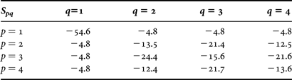
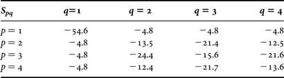
For typically chosen design frequency 2.4 GHz, the typical size of rectangular antenna-element is 49.4 mm × 41.4 mm. The thickness and the dielectric constant of the substrate are taken as 1.5 mm and 2.2, respectively. The basic parameters are tabulated [Reference Ali, Kamarudin, Md Tan and Rahman15] (Table 1). The radius of bends is taken as 0.65 mm. The obtained result shows a return loss as low as −54.6 dB and other S-parameters (in dB) are tabulated (Table 2). The phase shift obtained for S 11 is −22°, and for S 21, S 31, and S 41 is −130°. The design is implemented with 50 Ω characteristic impedance, so that it complies with the standards. The other parameters are calculated using [Reference Pozar14] and the radiation pattern in horizontal plane is plotted using simulator (Fig. 3).
Radiation pattern (in dB) in horizontal plane, obtained using FEKO EM simulator.
Parameters for Wilkinson power divider, used in FEKO EM simulator.

S-parameters (S pq) (in dB) as obtained using FEKO EM simulator.
IV. REDUCTION IN ANGULAR FREQUENCY
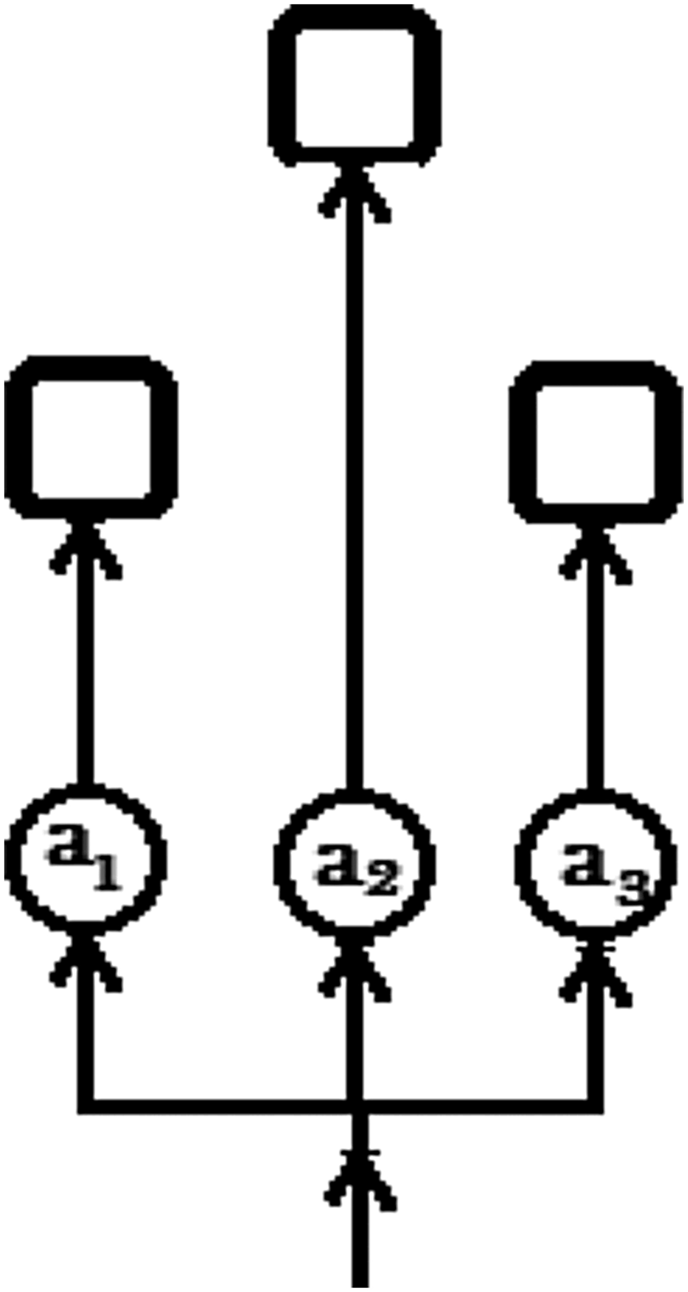
The signal to be transmitted is split into three equal parts as described (Section III) and attenuated to the ratio of a1, a2, and a3 and fed to each of the patches (Fig. 4). The parameters a1, a2, and a3 are varied sinusoidally. (In a practical case, for this purpose, a PIN diode may be used as voltage controlled variable attenuator, for that the voltage may be generated from a microprocessor to be fed to a PIN diode to vary the attenuation sinusoidally. However, the insertion loss needs to be tightly controlled otherwise it may drastically affect the system performance.) The frequency of the variation is kept same as the desired frequency of rotation. The sinusoids are 2π/3 phase separated with respect to themselves. This amplitude modulates the signal, envelop being the sinusoid of desired frequency of rotation (Fig. 5). This makes the average amplitude of excitation to antenna vary as desired with low frequency and, hence, the pattern rotates with the desired frequency.
Functional block diagram for the final design for reducing the frequency of rotation.
Selection and variation of the excitation coefficients a1, a2, and a3, the magnitudes of excitation of each array.
Under the considered condition the AF may be written as:
 $$\eqalign{& AF\left({\displaystyle{\pi \over 2}\comma \; \, \varphi } \right)= \cos \lpar \omega \, t\rpar \, {e^{j\lpar \cos \varphi + 2\pi f{\kern 1pt} t\rpar }} + \cos \left({\omega \, t + 2\pi /3} \right)\, \cr & \quad {e^{j\left[{\cos \left({\varphi - 2\pi /3} \right)+ 2\pi f{\kern 1pt} t} \right]}} + \cos \left({\omega \, t + 4\pi /3} \right)\, {e^{j\left[{\cos \left({\varphi - 4\pi /3} \right)+ 2\pi f{\kern 1pt} t} \right]}}.}$$
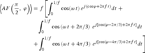
As kr(=2πr/λ, λ being wavelength) is governed by the ratio r/λ, and introduces an additional phase shift. Here, for the simple qualitative analysis, kr is taken as 1 in (6), which will not introduce any additional phase shift.The time averaged AF over time-period of 1/f is:
 $$\eqalign{\left\langle {AF\left({\displaystyle{\pi \over 2}\comma \; \varphi } \right)} \right\rangle & = f\left[{\vint_0^{1/f} {\cos \lpar \omega \, t\rpar \, {e^{j\lpar \cos \varphi + 2\pi f{\kern 1pt} t\rpar }}} dt} \right. + \cr & \quad \vint_0^{1/f} {\cos \left({\omega \, t + 2\pi /3} \right)\, {e^{j\left[{\cos \left({\varphi - 2\pi /3} \right)+ 2\pi f{\kern 1pt} t} \right]}}} dt \cr & \left. { + \vint_0^{1/f} {\cos \left({\omega \, t + 4\pi /3} \right)\, {e^{j\left[{\cos \left({\varphi - 4\pi /3} \right)+ 2\pi f{\kern 1pt} t} \right]}}} dt} \right]}$$
Since, ω ≪ 2πf, cos(ωt) is nearly constant in the period of e j2πft. Applying this to (7) and a little mathematical manipulation will result in:
 $$\eqalign{& \big\langle {AF\bigg({\displaystyle{\pi \over 2}\comma \; \, \varphi } \bigg)} \big\rangle \, = K\big[{\cos \lpar \omega \, t\rpar \, {e^{j\cos \varphi }}} \cr & \quad + \cos \big({\omega \, t + 2\pi /3} \big)\, {e^{j\cos \big({\varphi - 2\pi /3} \big)}} \cr & \quad{ + \cos \big({\omega \, t + 4\pi /3} \big)\, {e^{j\cos \big({\varphi - 4\pi /3} \big)}}} \big]\comma \; }$$
where K is a complex number, which will add to phase difference. The obtained (8) is similar to (1), which corresponds to a rotating field with angular frequency of ω instead of 2πf, which may be used to plot the AF pattern (Fig. 6(a)).
Since the ratio of excitation coefficients, a1:a2:a3 governs the direction of beam, fixing the values of the excitation coefficients a1, a2, and a3 can make the beam stop at a particular angle. In the case of stopping the beam at a particular angle, by fixing the values of the excitation coefficients, the corresponding phase shift may be given and there is no more sinusoidal variation of these coefficients. The variation in the values of excitation coefficients can be achieved with the use of voltage controlled variable RF attenuator circuit, which can be easily realized using PIN diodes [Reference Zhuo, Yan and Yu16]. This low frequency signal can be generated by a digital device making the device programed for different frequencies and different directions. This makes the device highly versatile to be used in large number of applications. Many protocols can be developed to use the devices installed with this mechanism to make it power efficient and to maximize throughput of closely spaced networks. The same mechanism is tested on FEKO EM simulator. Since, the radiation pattern of dipole in horizontal plane is omni-directional, one may model the element of the array as a dipole antenna to study AF of the array, and the radiation patterns are plotted for five different combinations of the excitation coefficients a1, a2, and a3 by sampling the sinusoids five times in a complete half cycle (Fig. 6(b)).
It would be of interest to see a comparison between the results obtained using analytical equation and that using FEKO EM simulator. For a case study, one may consider an element of the array to be a half wavelength dipole antenna, the radiation pattern of which may be written as:
 $${E_\theta } = j\displaystyle{{{I_0}{e^{ - jk\, r}}} \over {2\pi \, r\sin \theta }}\left[{\cos \left({\displaystyle{{k\lambda } \over 4}\cos \theta } \right)- \cos \left({\displaystyle{{k\lambda } \over 4}} \right)} \right].$$
One can note that the radiation pattern is independent of φ, which makes it omni-directional. Therefore, the radiation pattern of the array in the azimuthal plane (θ = π/2) becomes:
 $$\eqalign{& {E_\theta }\, \lpar \theta = \pi /2\rpar = jK\displaystyle{{{I_0}{e^{ - jk\, r}}} \over {2\pi \, r}}\left[{\cos \lpar \omega \, t\rpar \, {e^{j\cos \varphi }}} \right. + \cr & \quad \cos \lpar \omega \, t + 2\pi /3\rpar \, {e^{j\lpar \cos \varphi - 2\pi /3\rpar }}\left. { + \cos \lpar \omega \, t + 4\pi /3\rpar \, {e^{j\lpar \cos \varphi - 4\pi /3\rpar }}} \right].}$$
The additional terms get absorbed in K, and contribute uniformly to amplification and phase shift. This transformation only sets an initial offset to the rotation given by arg(K′), where K′ = jKI 0e −jkr/2πr. Normalizing the radiation pattern for qualitative overview and plotting generate Fig. 6. One may pick a curve for AF pattern obtained at the instant 2π/3ω from Fig. 6(a) and the corresponding result obtained using FEKO EM simulator from Fig. 6(b) to present the comparison of the two methods (Fig. 7). The deviation of presented analytical result with that using FEKO EM simulator (Fig. 7) may be understood due to the mutual impedance effect ignored in analytical equation, which was discussed for uniform circular arrays in [Reference Ioannides and Balanis13].
AF patterns obtained (a) using (8) at various instant: (i) 2π/3ω (dotted curve), (ii) 4π/3ω (solid curve), and 2π/ω (dashed curve); and (b) using FEKO EM simulator for different combinations of the excitation coefficients a1, a2, and a3.
A comparative AF pattern obtained at the instant 2π/3ω using analytical equation (dotted curve) and the corresponding result obtained using FEKO EM simulator (solid curve).
One may think for a circular antenna-array of rectangular microstrip antennas with number of elements more than three (N > 3), each fed with phase difference of 2π/N between two consecutive array elements, however, increasing number of elements will need more space as the size of each element is assumed to be same which might be impracticable [Reference Ahmed and Ali17]. The proposed design can be easily extended for very directive antennas simply by adopting a suitable geometrical array structure. It will still be better than the presently used smart antennas that employ tens of elements and switch each of them for different phase in order to achieve relatively small directional flexibility but accommodating large structured antenna on mobile devices may not be practicable. The paper uses the array factor based formulation for circular antenna-array.
V. CONCLUSION
The paper has proposed an antenna-array mechanism whose radiation pattern can be rotated with desired speed and can be stopped at any desired angle. The rotation and direction can be programed by any simple computing device. In mobile ad-hoc networks, the incorporation of proposed system may trigger the development of new routing algorithms in new scenario. It should possess higher energy efficiency and higher throughput. It can reduce the impact of “exposed node problem” several folds to increase the throughput in same proportion.
Rachit Garg is undergraduate (B. Tech.) student at Electronics and Communication Engineering Department of Indian Institute of Information Technology, Allahabad, India since 2009. His current research interests include computer aided design of microstrip antennas-arrays.
Gaurav Mishra is undergraduate (B. Tech.) student at Electronics and Communication Engineering Department of Indian Institute of Information Technology, Allahabad, India since 2009. His current research interests include computer aided design of microstrip antennas-arrays.
 Neetesh Purohit received his B. Tech. from Barkatullah University – Bhopal, India, M. Tech. from Rajiv Gandhi Proudyogiki Vishwavidyalaya – Bhopal, India, and Ph.D. from Devi Aahilya Vishwavidyalaya – Indore, India, in 1998, 2001, and 2008, respectively. He was Lecturer at Devi Aahilya Vishwavidyalaya – Indore, India. He has been working as assistant professor at Indian Institute of Information Technology, Allahabad, India since 2006. He has authored/co-authored more than 40 research articles, and his current research interests include antenna design for low power applications, digital signal processing and wireless communication technologies.
 Vishal Kesari received M. Sc. (Physics) degree from Purvanchal University, India, and Ph. D. (Electronics Engineering) degree from Banaras Hindu University (BHU), India, in 2001 and in 2006, respectively. He was Lecturer at Birla Institute of Technology – Mesra, Ranchi, India and at Indian Institute of Information Technology – Allahabad, India. Currently, he is Scientist at Defence Research and Development Organization, Bangalore, India. His research interest includes interaction structures for microwave and millimeter-wave vacuum electronic devices. He has authored a book: Analysis of Disc-loaded Circular Waveguides for Wideband Gyro-TWTs, LAP – Lambert Academic Publishing AG & Co., Germany (ISBN: 978-3-8383-1145-6), 2009, and several research papers in peer-reviewed journals and conference proceedings.