NOTATIONS
- a
speed of sound
- A bl
blade area
- A rot
rotor disc area
- cMR
main rotor blade chord length
- CT
thrust coefficient
- C lα
lift curve slope
- E rot
rotational energy
- E trans
translational energy
- g
gravitational acceleration
- J β
blade flap moment of inertia
- J ζ
blade lag moment of inertia
- l fus
fuselage length
- mF
fuel mass
- m MTOM
maximum take-off mass
- m OEM
operating empty mass
- mP
payload mass
 ${\dot{m}_F},{\bar{\dot{m}}_F}$
fuel flow, mean fuel flow
- Ma tip, MR
main rotor tip Mach number
- N bl, MR
number of blades per main rotor
- N rot, MR
number of main rotors
- R MR
main rotor blade radius
- s RNG
flight range
- s shaft
rotor shaft spacing
- t RNG
flight endurance
- T MR
main rotor thrust force
- vh
horizontal flight speed
- v tip, MR
main rotor tip speed
- γMR
main rotor lock number
- κov
overlapping factor
- κcutout
cut-out ratio of the rotor blade
- μ
advance ratio
- ΛMR
blade aspect ratio
- ρ
density of air
- σMR
rotor density of main rotor
- ΩMR
main rotor rotational speed
- CPACS
common parametric aircraft configuration scheme
- DLR
German aerospace centre
- EDEN
evaluation and design of novel rotorcraft concepts
- FEM
finite element method
- HOST
helicopter overall simulation tool
- MDO
Multi-disciplinary design and Optimisation
- RCE
remote component environment
- RIDE
rotorcraft integrated design and evaluation
- TLARs
top level aircraft requirements
Symbols

Abbreviations
1.0 INTRODUCTION
The design of rotorcraft is comparable to the design of fixed-wing aircraft and is a highly multi-disciplinary process. The technical layout and scaling of a rotorcraft design with respect to its Top Level Aircraft Requirements (TLARs) has a crucial impact on the performance of the resulting vehicle. It is important for a design process, to ensure an increase of the accuracy of all parameters with every design step. The layout of the tools, meaning the arrangement of the tools in the process, must be performed carefully. The subject of this paper is the presentation of the strategy and doctrine of the new rotorcraft design environment which is developed at DLR.
In common references for aircraft design, like Raymer(Reference Raymer1) or Nicolai(Reference Nicolai and Carichner2), the design process is divided into three main phases: the conceptual design, the preliminary design and the detailed design. Other references, for example, Layton(Reference Layton3), extend the three phases with a concept study at the beginning and a design proposal between the preliminary and the detailed phase. Figure 1 shows the three phases applied to rotorcraft design. As a result of the first design phase, an external configuration and a scaling of its properties are provided. This includes the dimensions of the rotors, the fuselage, the cabin and a mass breakdown. At the end of the second phase, a final contour of the external shape is provided in order to describe every point on the outer hull. In addition, a layout of the internal configuration is developed to predict the mass and balance characteristics as well as the position of the structural parts. The third phase delivers the detailed production drawings. The accuracy of every phase is shown in the last column of Fig. 1.
Rotorcraft design process in three phases based on a generic scheme according to Raymer(Reference Raymer1) or Nicolai(Reference Nicolai and Carichner2).

In the 1980s and still in the 1990s, one school of thought of rotorcraft design was to freeze a design after every phase. Results of a previous design phase were not allowed to be changed in the following phases. With the introduction of computational multi-disciplinary design programs, the borders of the phases became blurred. According to Roskam(Reference Roskam4), 65% of the lifecycle costs are determined after the end of the conceptual design phase. After the end of the preliminary design phase, 85% of the upcoming costs cannot be influenced anymore. In the classic design approach, the configuration was fixed after the conceptual design. But the best choice of a configuration includes methods from the first and second design phases. The knowledge about system integration or structural weights, which will be gained in the second design phase, can be of crucial importance when making a decision for a final configuration. Nevertheless, the interim goals of the phases, according to Fig. 1, have a practical background and are reasonable for the layout of a new design process.
The determination of the external configuration is the most crucial step in the design process. At this point, the major dimensions and many performance characteristics are defined. Therefore, the objective of this modern rotorcraft design project is a process chain that combines the tools of the conceptual phase and the preliminary phase. The methods presented in this paper alternate between performing design tasks and analysis tasks. The essential result is the suitable layout of the tools in a design framework according to their fidelity and computational time demand.
In recent years, several aerospace research organisations presented approaches for multi-disciplinary design optimisation (MDO) in the field of rotorcraft engineering. The works of NASA(Reference Johnson5) on NDARC, NLR(Reference Boer and Stevens6), Georgia Tech(Reference Khalid and Schrage7) and ONERA(Reference Basset, Tremolet, Cuzieux, Schulte, Tristrant, Lefebvre, Reboul, Richez, Burguburu, Petot and Paluch8) with the CREATION project are notable. With the intention to consider and assess miscellaneous configurations for one mission, DLR follows a different approach.
In 2011, DLR started the RIDE project (Rotorcraft Integrated Design and Evaluation) to build up a process chain for helicopter design. Within RIDE, the DLR-internal collaboration between the Institute of Flight Systems, the Institute of Aerodynamics and Flow Technology (both in Braunschweig) and the Institute of Structures and Design in Stuttgart began. The objective was to build an integrated, automated and multi-disciplinary design process given only mission requirements. As little input as possible was required to start the process.
In the project, new calculation tools were developed and many tools from the fixed-wing design were adapted to the boundary conditions of rotorcraft design. It was not the purpose of the project to design a specific helicopter. In this period, the standard configuration with one main and one tail rotor was studied. Besides the development of the design process, the development of a dataset was carried out to save all information about a virtual rotorcraft in one file. The conception behind these activities was to gather knowledge about the design process of rotorcraft and to create a toolbox for generic and virtual design.
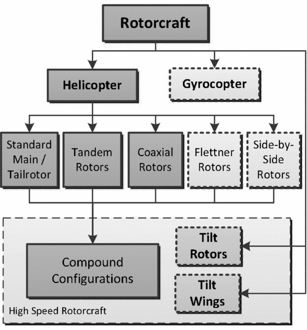
In 2014, the results and findings of the project evolved into a new project called EDEN (Evaluation and DEsign of Novel rotorcraft concepts). Basic work packages of EDEN are the extension to novel rotorcraft configurations and the porting of the tools used in RIDE to the new Remote Component Environment (RCE) framework software. With the extension to more configurations, the scaling loop had to be rebuilt. Figure 2 shows a classification of rotorcraft. The solid boxes point out the configurations which are taken into account in the project. The design of a rotorcraft with more than one main rotor is an inherent capability of the final design process.
Types of rotorcraft.

The most frequently used rotorcraft configuration has one main rotor and one tail rotor to compensate the main rotor torque. Unconventional configurations have two counter-rotating main rotors. The tandem and coaxial rotor arrangements, the intermeshing or Flettner rotor arrangement and the side-by-side rotor arrangement are mentioned here. Besides the classic standard configuration, the tandem and coaxial configurations are implemented in the design process.
Modern designs, so-called compound configurations, have a combination of rotating wings, fixed wings and a thrust generator acting in the flight direction. By adding lifting surfaces and propellers or jet engines, all three main configurations can be made into a compound configuration. The complex interaction of the components makes the consideration of the possible configurations decidedly more difficult.
2.0 DESIGN PROCESS
2.1 Software framework and data format
The three involved DLR institutes require a suitable connection of their servers to ensure the availability of the computational tools. Furthermore, the tools require a sophisticated harmonisation with each other to ensure the data transfer between them. Since 2016, the connection and control of the dispersed tools is performed by the RCE framework software (Bachmann(Reference Bachmann and Kunde9), Litz(Reference Litz, Seider, Bachmann and Kunde10) and Seider(Reference Seider, Fischer, Litz, Schreiber and Gerndt11)). Authorised users are able to start the tools remotely, but cannot access the source codes. The local users are responsible for software maintenance.
The harmonisation of the various tools is done via the Common Parametric Aircraft Configuration Scheme (CPACS) exchange format. This is an XML data structure developed for design processes delivering a standardisation of the input and output parameters for every computational tool (see Bachmann(Reference Bachmann, Kunde, Litz, Schreiber and Bertsch12) and Liersch(Reference Liersch and Hepperle13)). The hierarchical structure allows saving all parameters in one file. Different tools can exchange information via this structure.
The use of RCE in conjunction with CPACS creates a very high level of flexibility and modularity. A tool adapted to CPACS can easily be rearranged or exchanged in the RCE workspace. This characteristic has shown to be very suitable during the development of the process. CPACS was extended and adapted for rotorcraft design. Therefore, all parameters regarding rotating wings, the drive train and the fuselage geometry had to be included.
2.2 Tool classification
In order to find the most suitable layout for the process, the design tools were divided into four groups ranging from Level 0 to Level 3. Level 0 tools operate with statistical parameters with only a limited amount of physical modelling and produce many export values out of a few import values. They were used to initialise datasets at the beginning of a design process. Level 1 tools have physical models of medium to good fidelity. The calculation time ranges from seconds to a few minutes. They can be used iteratively in a loop. Level 2 tools have advanced physical models, but an increased time demand which is too high to use them in a loop. Their pre-and post-processing procedures are done automatically and allow a combination with the Level 0 and Level 1 design tools. They are arranged as a queue and do not perform recursive procedures. Repeated executions are controlled by the user. In contrast to this, the Level 3 tools are all tools which are currently not suitable for the framework, but may be used later. Either their computation time exceeds the maximum time allowed or the pre-and post-processing procedures cannot be performed automatically.
2.3 Design workflow
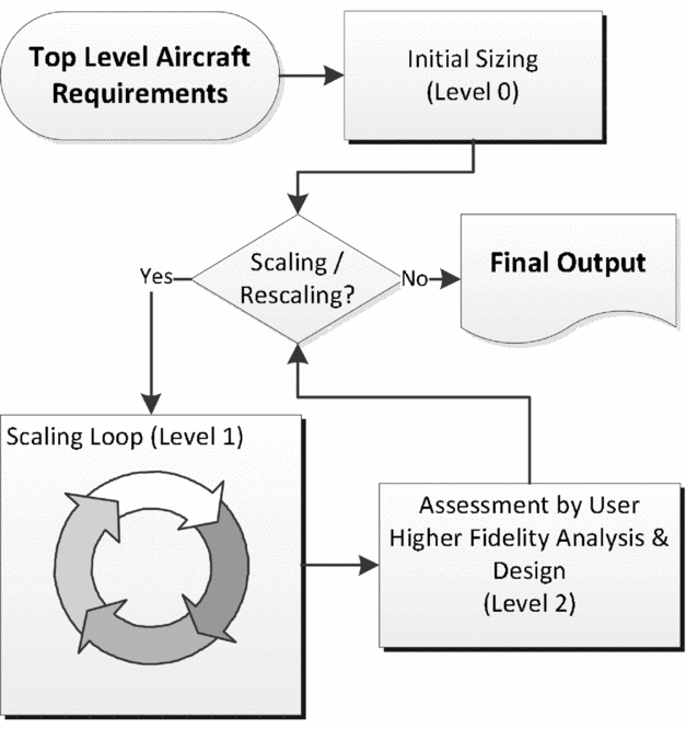
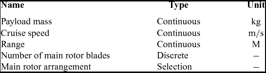
Figure 3 shows the basic layout of the design process. The minimum TLARs that have to be provided by the user to initialise the computation are given in Table 1. These requirements stay constant over the complete process, unless they are changed by the user. The first three requirements determine the performance. A specific payload mass has to be transported over a specific flight distance with a required flight speed.
Flowchart of main tool groups in the design process used in EDEN.

Minimum top-level design requirements to start the process

The last two inputs determine the rotor configurations. The number of blades per main rotor increases with the maximum take-off mass. This number is important for the configuration of the rotor hub and the blade attachment. As a guideline for the selection of the number of blades, here are some statistical data: Teetering rotors with two blades are used up to an mMTOM of almost 8 metric tons. Three-bladed rotors have the widest scope of application, especially for unconventional configurations, like coaxial rotors with 13 tons and tandem rotors with 22 tons mMTOM. In this case, the total number of blades for the complete rotorcraft is six. Hingeless rotors with four blades are used up to 6 tons mMTOM. Four or five blades are reasonable for fully articulated rotors up to 10 tons mMTOM. Above 10 tons, articulated rotors with five blades have to be considered. Quite often, the configuration and the number of blades are given by the customer.
The rotors are arranged according to the selected configuration (see Fig. 2). A scaling of the rotors and the fuselage is performed followed by a prediction of the aerodynamic and engine properties. The first tools work mostly statistically with only a few, simple physical models. Level 0 design tools are used here. Results are the operating empty mass and the fuel mass allowing the first estimate of the maximum take-off mass.
 $$\begin{equation}
{{m_{\rm MTOM}} = {m_{\rm OEM}} + {m_{\rm P}} + {m_{\rm F}}}
\end{equation}$$
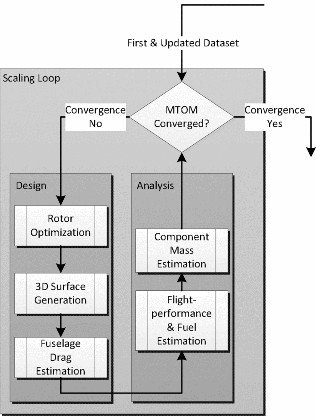
The first sizes of the rotors, fuselage and stabilizers are determined. At that point, the dataset is sufficiently filled in order to perform a flight mechanical simulation, but only with statistical accuracy (±20%). The created dataset is then passed on to a scaling loop. In addition, Figs 3 and 4 shows the basic layout of the loop. It iterates the maximum take-off mass in relation to the operating empty mass and the fuel mass.
Detailed flowchart of the scaling loop inside the process chain.

The tools of the loop are separated into design and analysis tasks. The tools in the design leg scale and optimise the components of the rotorcraft with respect to the TLARs and mMTOM. The tools in the analysis leg perform a recalculation on the basis of the previous scaling. The first step is a flight performance calculation to obtain an updated fuel mass. The second step is the estimation of the component masses to obtain an updated operating empty mass. The new mMTOM is simply calculated by Equation (1). Inside the loop, a two-staged optimisation of the main rotor blades is performed. The first stage optimises the planform applying a constraint problem, minimising the rotor's mass. The second stage optimises the blade twist for lowest power consumption in cruise flight. A 3D-model is created according to the size of the rotors and the fuselage followed by a calculation of the fuselage drag. In the next step, an analysis is conducted recalculating the needed fuel for the required range and calculating the operating empty mass by computing and adding up the component masses. After completing the design and analysis a convergence check is performed: Is the recalculated m MTOM within close margins of the original m MTOM? If convergence is achieved, the dataset is assessed by the user, see Fig. 3. At this point, the Level 2 design tools can be initiated to perform further design and analysis of the structure and parameter studies. The user can make manual changes to the design if desired. If a Level 2 analysis tool points out an element for reconsideration, like improvable component masses or insufficient power, the dataset will be updated. All updates and changes require a restart of the scaling loop (to be performed manually by the user) until the design converges and is consistent again.
A consistent design has no inconsistencies between its external configuration, its mass breakdown and its flight performance. The input for the scaling loop is a CPACS file with all the required data for the computation. This file can be an initial dataset or a saved file from a previous scaling. Storing an old design and restarting the scaling loop with a modified design allows the production of a variety of possible configurations in order to compare and select the top design.
3.0 INITIALISATION AND FIRST DATA
3.1 Masses and rotor arrangement
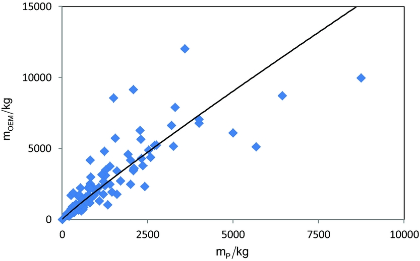
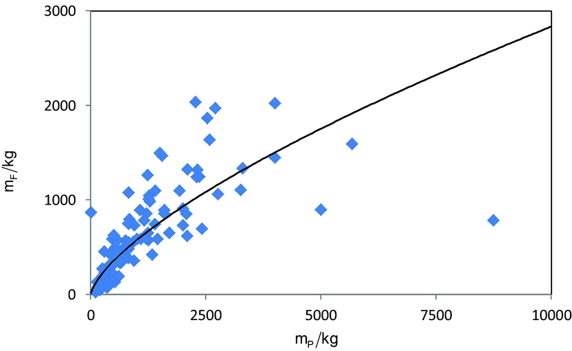
The initialisation of the process creates the initial dataset. The basis for this first step is the statistical data of 159 existing helicopters. Depending on the TLARs (Table 1), the initial sizes, the operating empty mass and the fuel mass are determined. Figure 5 shows a plot of the operating empty mass over the payload mass statistics. In addition, Fig. 6 gives a plot of the fuel mass over the payload mass statistics. Regression curves are given for both diagrams. A prediction of the required fuel mass for all available configurations is less accurate because of limited statistic knowledge for novel configurations. Thus, the prediction of the initial fuel mass is decoupled from the required range. The masses according to Equation (1) give the initial m MTOM as the basis for the scaling loop. There the fuel mass is accurately calculated from trimmed flight states.
Statistics of the operating empty mass over the payload mass with a regression curve.

Statistics of the fuel mass over the payload mass with a regression curve.

From the given TLARs and the initial m MTOM, the sizes of rotors and stabilizers are determined by the use of regression functions. The rotors and stabilizers are located in a virtual design frame with a sensible spacing to ensure safety and little interaction. This is automatically performed for the desired configuration by starting the initialisation tool. Rotor 1 in the dataset is either the main rotor for the standard configuration, the front rotor for the tandem or the upper rotor in the case of the coaxial configuration. Rotor 2 is consequently the tail rotor, rear rotor or lower rotor.
3.2 Fuselage design
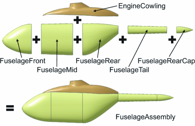
A complete fuselage consists of the body, the engine cowling and the tail boom. The body can be separated into FuselageFront with cockpit and avionics, FuselageMid with the cabin and FuselageRear with a possible ramp or a cargo hold. Figure 7 shows the arrangement of the components. If initialising the process with only five TLARs (see Table 1), the size of the fuselage, particularly of the body, is derived from statistics, starting with the overall fuselage length. The fuselage length measures from the nose over the fuselage body to the end of the tail boom.
Components of the generic fuselage.

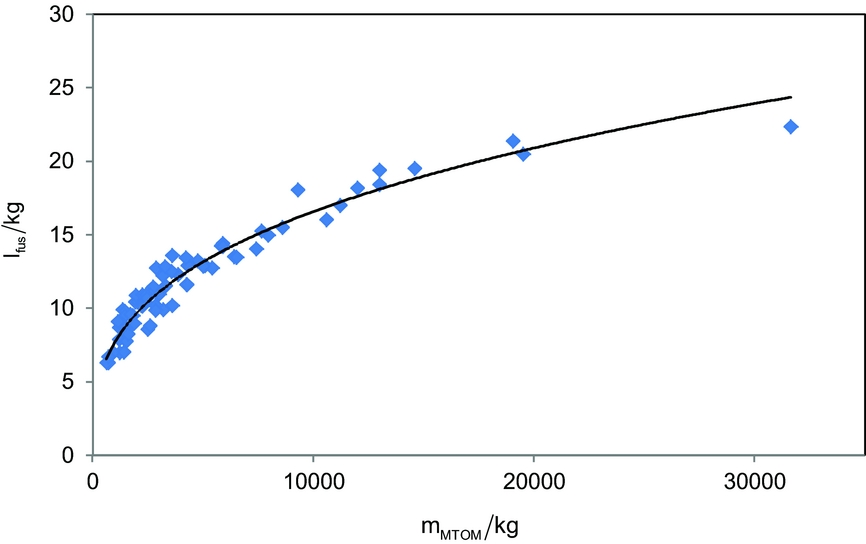
Figure 8 shows the statistics of the fuselage length over the take-off mass with a regression curve. The correlation of the curve and the statistics is very good. Further geometric ratios allow the sizing of the body with respect to m MTOM. The dimensions of the front and rear fuselage body are derived using default ratios, but they may change by adding requirements for retractable nose gears or enhanced avionics at the front or special loading characteristics at the stern ramp.
Statistics of the fuselage length over the maximum take-off mass with a regression curve.

The second possibility is to give specific cabin dimensions as an input in addition to the five minimum TLARs. For instance, the smallest design for the concept study “Rescue Helicopter 2030” (Rettungshubschrauber 2030) requires at least a cabin volume of 6 m³. A possible cabin has a length of 2.7 m, with a cross-section of 1.5 m × 1.5 m. The dimensions of the generic fuselage are scaled according to the required cabin measures. The FuselagMid component contains the cabin. The Fuselagefront and FuselageRear are sized from design parameters (default values or changed by the user) and the cross-section of the FuselageMid component.
The body is arranged under the rotors with the centre of the payload mass in the centre of gravity of the complete configuration. The tail boom and the engine cowling are sized according to the arrangement of rotors and body. The dimensions of every component are stored in the CPACS dataset. Later, a 3D-model will be created from this data.
3.3 Initial power and performance parameters
The first estimate of the required power is obtained by a semi-empirical approach from the initial mMTOM using an actuator disc model. The required power is used for the initial scaling of the components of the drive train and the flight systems. Based on the statistics of 69 turboshaft engines installed in helicopters, additional parameters like fuel consumption and engine mass are obtained. The aerodynamic drag of the fuselage and the hub is initially estimated from statistical data. During the scaling loop the required power will be calculated for trimmed flight states by the use of blade element theory. The drag of the fuselage will be calculated from a 3D model.
4.0 ITERATIVE PROCESS AND OPTIMISATION
The second paragraph already dealt with the general concept of the scaling loop. The tools shown in Fig. 4 are now viewed in more detail. The typical tools used for such a scaling loop are marked as Level 1 design tools. In this loop, the dataset is scaled to a consistent design. In total, three internal loops were used inside the outer scaling loop. The other programs in the loop are arranged in a queue. The dataset iterates until the maximum take-off mass converges, resulting in consistent size, masses and flight performance. Some of the following steps require a complete simulation of the helicopter in a trimmed flight state. Hence, this calculation is described before the design tools of the loop.
4.1 Helicopter overall simulation tool
For the simulation of different flight states, DLR uses the HOST (Helicopter Overall Simulation Tool)(Reference Benoit, Kampa, von Grünhagen, Basset and Gimonet14) software. Trim calculations are performed for the required flight states. The rotor aerodynamics are calculated by the use of the blade element theory. The loads of the lifting surfaces, either stabilizer or wing, are calculated from finite wing polars. The flow properties in forward flight and aerodynamic interactions of the fuselage, the stabilizers and optional wings are estimated by build-in models. In these calculations the Pitt/Peters model is used, see Pitt and Peters(Reference Pitt and Peters15) and Chen(Reference Chen16). Optional thrust generators, either propellers or jet engines, are applied by scalable point loads. The thrust of the additional propulsive force is scaled to meet the required trim state.
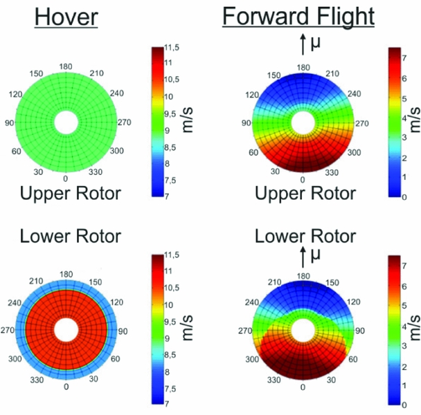
The modulation of rotor-rotor interference in HOST is limited. Depending on the overlapping ratio of two rotor discs the lower rotor shows an area, where the blades perform a continuing climb. Figure 9 shows the velocity distribution perpendicular to the rotor disc of a coaxial rotor system in hover and forward flight. The lower part exhibits the area where the contracted mass flow of the upper rotor penetrates the lower rotor disc. The hover flight shows the largest area of interference. This area decreases with increasing flight speed. Methods to calculate the superposition of the two mass flows are presented by Leishman(Reference Leishman17) and Johnson(Reference Johnson18). In contrast to isolated rotors, the combined rotor system shows an additional interference power. Leishman(Reference Leishman17) demonstrated approaches to estimate the interference power using momentum theory. Here, the contracting mass flow of the upper rotor is added to the mass flow through the lower rotor disc. Compared with experimental data, Leishman gives an increase about 16 % of the induced power for a combined coaxial rotor system. Commonly, the interference power decreases, by an increase of plane spacing and shaft spacing. Tandem configurations with an overlapping of 0.66·RMR show a hover interference power of 13 % of the induced power.
Induced velocities through the discs of a coaxial rotor system in hover (left) and at an advance ratio of 0.08.

For the trim and performance calculation using blade element method, the contracting mass flow is modelled and added to the opposite rotor resulting in velocity distributions like shown in Fig. 9. Hence, one calculation has to be performed for each isolated rotor without interference in order to get the information about the induced velocity field. Then the trim calculation is repeated with superposed induced velocity fields for each rotor. The result certain areas on the lower rotor disc, which exhibit additional perpendicular velocity and influencing the performance of the complete rotor system.
This approach accounts for nearly three quarter of the maximum interference power in hover. The computation is fast enough to be integrated into the primary scaling loop for conceptual design. Every time a trim calculation is performed for the maximum speed the required power is updated by the last computation. This happens two times in the scaling loop, after optimising the blade twist and after calculating the fuel mass. Every following tool has the most recently calculated power as an input.
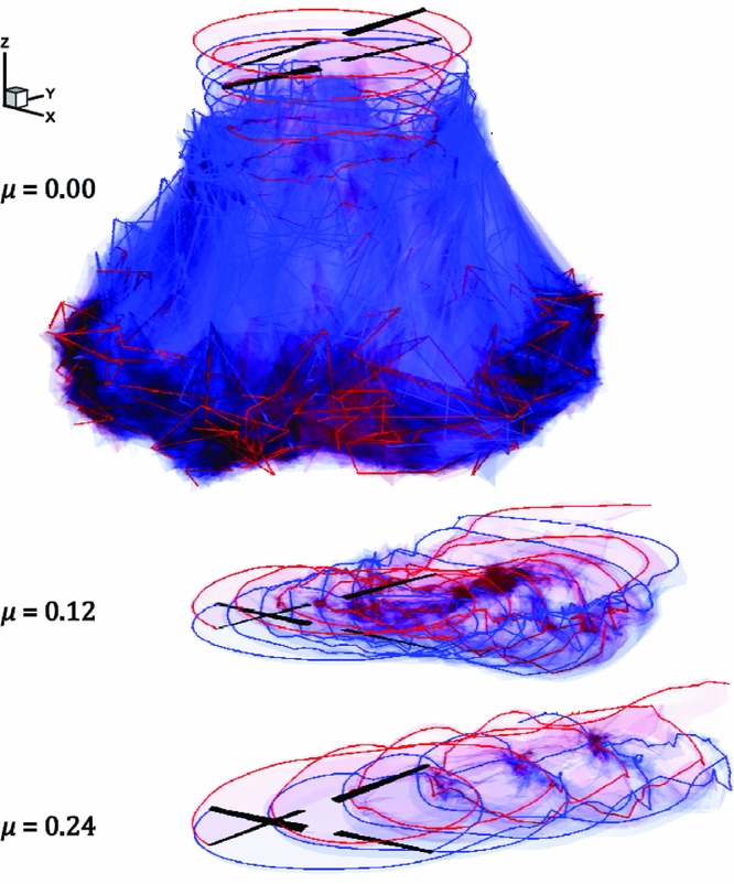
The accurate prediction of the interference between rotors and lifting surfaces is a problematic calculation in particular because of the great time demand of the iteratively working tools. Higher order investigations were conducted by Kunze(Reference Kunze19) using the unsteady panel and free-wake code UPM. Figure 10 shows a first impression of the volume solution given by UPM in contrast to the blade element solution shown in Fig. 9. The calculations showed a very good prediction of the induced power, taking the flow around the complete configuration into account. Nevertheless the test cases exhibit a massive time demand for sufficient results. An initially desired coupling of UPM with HOST inside the scaling loop has shown not to be suitable.
Visualisation of the calculated wake of the coaxial rotor at three different advance ratios.

4.2 Optimisation of blade planform and rotor speed
In the first step of the rotor optimisation, the planform of the blade and the rotor speed are optimised to minimise the rotor masses. At a later stage the twist distribution is optimised to minimise the required power. Optimisation of the tapering of the blade has not been implemented yet.
The cost function for the first stage is the mass of the rotating parts. The mass is customised through the optimisation by adapting the rotor radius, the chord length and the rotor speed. The adaptation of the planform parameters is limited by constraints. These constraints take different flight conditions into account. The approach has shown to be very appropriate. RCE provides a set of optimisation codes, which had to be configured for a specific problem. In the following case the COBYLA (Constrained Optimisation BY Linear Approximation) algorithm from Powell(Reference Powell20) was used. COBYLA is an optimisation code without calculation of gradients for a constrained problem developed for Westland Helicopters in 1994. In the following, the characteristic rotor parameter constraints, which can optionally be adapted by the user, are presented. The values presented are the default values.
Equations (2) and (3) provide the blade aspect ratio and the blade density. Suitable lower and upper constraints for the aspect ratio range from 12 to 25.
 $$\begin{equation}
{\Lambda _{\rm MR}} = \frac{{{c_{\rm MR}}}}{{{R_{\rm MR}}}}
\end{equation}$$
The values for the blade density are slightly increasing over the take-off mass. In general, 0.03 for lower and 0.15 for upper constraint are applied.
 $$\begin{equation}
{\sigma _{\rm MR}} = \frac{{{N_{\rm bl,MR}}{A_{\rm bl,MR}}}}{{\pi {\rm R_{MR}}^2}}
\end{equation}$$
Helicopters with more than 10 metric tons maximum take-off mass typically have values greater than 0.1. The blade area is calculated with Equation (4) . The non-lifting circular area around the shaft is considered. The size of this cut-out is a design parameter. Its default value, which may be changed by the user, is 20% of the blade radius. Typically, this value decreases with increasing mMTOM.
 $$\begin{equation}
{A_{\rm bl,MR}} = {c_{\rm MR}}\left( {1 - {\kappa _{{\rm{cutout}},{\rm MR}}}} \right){R_{\rm MR}}
\end{equation}$$
The blade loading (Equation (5)) is most suitable to assess the aerodynamic capacity of a rotor with respect to blade stall.
 $$\begin{equation}
{\left( {\frac{{{C_T}}}{\sigma }} \right)_{\rm MR}} = \frac{{{T_{\rm MR}}}}{{\rho {N_{\rm bl,MR}}{A_{\rm bl,MR}}{v_{\rm tip,MR}}^2}}
\end{equation}$$
Small values of the blade loading are leading to small lift coefficients in the blade sections, but high drag coefficients are due to friction. Values which are greater than 0.12 indicate first flow separations somewhere on the rotor disc. The values for the majority of all transport helicopters are below 0.1. In hover, it should be between 0.07 and 0.09. Values of 0.07 and 0.12 are used as defaults for lower and upper constraints.
Equation (6) gives the tip Mach number at cruise speed. The value is constrained by the state of the art of transonic design of the rotor tip and the aerofoil. Besides the dynamic stall at the inboard side of the retreating rotor blade, the tip Mach number is the speed limiting value of the flight envelope. Maximum values of more than 0.9 are possible but economically not sensible. Maximum Mach numbers of 0.85 are reasonable for an upper constraint at cruise conditions, without unloading the disc by the use of lifting surfaces.
 $$\begin{equation}
M{a_{{\rm{tip}},{\rm{cruise}},MR}} = \frac{{{v_{{\rm{tip}},MR}} + {v_{h,{\rm{cruise}}}}}}{a}
\end{equation}$$
High values of the advance ratio (Equation (7)) are desirable, but with respect to the tip Mach number on the forward moving rotor side and flow separation on the backward moving rotor side not practical.
 $$\begin{equation}
\mu = \frac{{{v_{h}}}}{{{v_{{\rm{tip}},{\rm MR}}}}}
\end{equation}$$
An advance ratio of 0.4 is typical for modern helicopters at maximum speed leading to a tip Mach number of about 0.9 without decelerating the rotor. The maximum flight speed is markedly higher than the cruise speed, which usually has an advance ratio of 0.35 in conjunction with a tip Mach number of around 0.85. The corresponding tip speed for Equations (5)–(7) is given with Equation (8).
 $$\begin{equation}
{v_{{\rm{tip}},{\rm MR}}} = {\Omega _{\rm MR}}{R_{\rm MR}}
\end{equation}$$
For existing helicopters the tip speed ranges between 190 m/s and 220 m/s with a tendency to 220 m/s. There are light and ultralight helicopters with tip speeds of about 150 m/s, but these are exceptions which are avoiding transonic flow on the forward moving blade. The small interval in which the value ranges balances the blade loading (Equation (5)) with the tip speed in the denominator and the tip Mach number (Equation (6)) where the tip speed is in the numerator. The rotational speed used in Equation (8) is indirectly limited by the constraints on blade loading and tip Mach number.
The ratio of the aerodynamic and gyroscopic forces is given by Equation (9) with the Lock number. It has a crucial influence on the flapping motion of the rotor blade.
 $$\begin{equation}
{\gamma _{\rm MR}} = \frac{{\rho {C_{l\alpha }}{c_{\rm MR}}{R_{\rm MR}}^2}}{{{J_\beta }}}
\end{equation}$$
Equation (9) shows the aerodynamic parameters in the numerator and the mass moment of inertia in the denominator. Low Lock numbers can always be connected with higher masses and inertia, which ensures a smooth transition into autorotation without a strong deceleration of the rotor. Rigid rotors can have values of 8 and more. In contrast to this, the fully articulated rotors are heavier and show Lock numbers of around 6. Combat helicopters may have values up to 10, which indicate very aggressive aerodynamics. For transport helicopters, values between 6 and 8 are typical. The lower and upper constraints for the Lock number are 6 and 9, respectively.
The next parameter concerns the capabilities of the helicopter to land with autorotation. The energy ratio is given by Equation (10). It is the ratio between the rotational energy of all the main rotors (assuming that all main rotors are equal in Equation (10)) and the translational energy of the complete configuration at the optimal vertical autorotation.
 $$\begin{equation}
\frac{{{E_{{\rm{rot}}}}}}{{{E_{{\rm{trans}}}}}} = \frac{{{\raise0.5ex\hbox{$\scriptstyle 1$} \kern-0.1em/\kern-0.15em \lower0.25ex\hbox{$\scriptstyle 2$}}{N_{{\rm{rot}}}}{N_{bl}}{J_\zeta }{\Omega _{MR}}^2}}{{{\raise0.5ex\hbox{$\scriptstyle 1$} \kern-0.1em/\kern-0.15em \lower0.25ex\hbox{$\scriptstyle 2$}}{m_{\rm MTOM}}\;v_s^2}}
\end{equation}$$
The descent velocity for ideal vertical autorotation is usually estimated to be 1.8 times the velocity of the induced downwash in hover, see Equation (11).
 $$\begin{equation}
{v_s} = 1.8\sqrt {\frac{{{m_{\rm MTOM}}g}}{{2\rho {\kappa _{ov}}\pi {R_{\rm MR}}^2}}}
\end{equation}$$
In Equation (11), an overlapping factor is introduced concerning the downwash of one main rotor onto a second. For a single main rotor, this factor is set to 1. For the tandem and the coaxial rotor arrangements, this factor is calculated by the use of Equations (12) and (13) according to Johnson(Reference Johnson18).
 $$\begin{equation}
{\kappa _{\rm ov}} = \sqrt {\frac{2}{{2 - m}}}
\end{equation}$$
with
 $$\begin{equation}
m = \frac{2}{\pi }\left[ {\arccos \left( {\frac{{{s_{{\rm{shaft}}}}}}{{2{R_{\rm MR}}}}} \right) - \frac{{{s_{{\rm{shaft}}}}}}{{2{R_{\rm MR}}}}\sqrt {1 - {{\left( {\frac{{{s_{{\rm{shaft}}}}}}{{2{R_{\rm MR}}}}} \right)}^2}} } \right]
\end{equation}$$
In case of a coaxial arrangement, with a shaft spacing of zero, Equations (12) and (13) result in the overlapping factor being the square root of 2. Equation (14) gives the resulting formulation of the energy ratio.
 $$\begin{equation}
\frac{{{E_{{\rm{rot}}}}}}{{{E_{{\rm{trans}}}}}} = \frac{{{N_{{\rm{rot}}}}{N_{\rm bl}}{J_\zeta }{\Omega _{\rm MR}}^2}}{{1.62\frac{{{m_{\rm MTOM}}^2g}}{{\rho {\kappa _{ov}}\pi {R_{\rm MR}}^2}}}}
\end{equation}$$
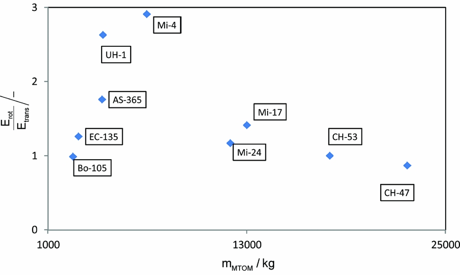
Figure 11 shows a group of existing rotorcraft analysed by Equation (14) and plotted over their maximum take-off mass. With a ratio of 1 it is not possible to fully decelerate a rotorcraft in vertical autorotation. At 60–70% of the nominal rotational speed, the stall occurs and the thrust breaks down. There are helicopters like the UH-1 and Mi-4 which are known to have good autorotation characteristics. The energy ratio values of these two helicopters are between 2.5 and 3. Values of less than 1 have to be avoided. Nevertheless, vertical autorotation is the last choice of emergency procedures, but the energy ratio has shown to be a very good measure to assess the general autorotation capabilities of a rotorcraft in an early design stage.
Energy ratios, according to Equation (14), over the maximum take-off mass for existing helicopters.

Changing the rotor radius influences the arrangement of fuselage, stabilizers and rotors. In case of a standard or tandem configuration, the radius influences the spacing between the rotor shafts. In case of coaxial and tandem configurations, the vertical spacing of the rotor planes has to be adapted with the radius. For the standard and coaxial rotors, the tail boom is adjusted by keeping the length of the fuselage body (cabin, cockpit and rear part) constant. For a tandem configuration, an adapted rotor radius is compensated by a change of the overlapping ratio of the rotor discs or the cabin length. The overlapping can increase up to 0.66·RMR resulting in an x-distance of 1.33·RMR between the two shafts. If this violates the minimum cabin length, the overlapping is relaxed. If the overlapping has to be relaxed, the new shaft spacing will be taken into account by Equation (13) in the next cycle of the scaling. In most cases, the overlapping radius stays at the maximum and the cabin part is lengthened. The cockpit and the rear part remain unchanged. This results in a higher payload volume at constant payload mass.
4.3 3D-surface generation and fuselage aerodynamics
From the optimised rotor geometry and the parameters for the fuselage body a 3D-model of the external configuration is created according to Fig. 7 (see Kunze(Reference Kunze21)). This external configuration or hull is the basis for the prediction of the aerodynamic properties of the fuselage. Furthermore, it is the external boundary for the structural design after the scaling loop. The 3D-model is created by lofting through several cross sections from the nose to the cap of the tail boom. A generic set of cross-sections is predefined in the tool. The length, width and height of the components, according to Fig. 7, are given by the previous scaling.
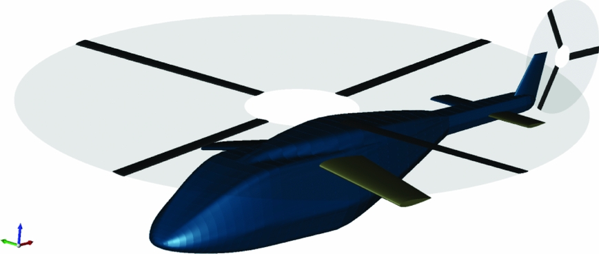
At this point, sufficient data are available to visualise the external configuration of the rotorcraft. The graphical visualisation of a CPACS dataset is performed by the DLR-developed TIGL-Viewer (see Siggel(Reference Siggel22)). An example is shown in Fig. 12.
Visualisation of the generic fuselage for a standard configuration with additional lifting surfaces.

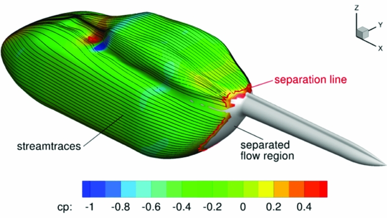
Based on the work of Kunze(Reference Kunze21), the aerodynamic properties of the 3D-model are calculated by the use of a modified version of VSAERO(Reference Maskew23). VSAERO uses a linearised 3D panel method coupled with a viscous solver. Figure 13 shows the pressure distribution on the surface of a fuselage up to the separation line. In general, the helicopter fuselage has a region of separated flow on the backside below the tail boom. Therefore, flow separation has to be taken into account.
Results of the calculation of the pressure distribution on the helicopter fuselage up to the separation line.

The first possibility to model the area of separated flow is by using wake panels. An automatisation of this procedure showed not to be reliable. The second method is to assume a constant pressure on the surface panels with separated flow. The line of separation is predicted by the boundary-layer code integrated into VSAERO. The value for the pressure coefficient behind the separation line can be calculated or manually set. The aerodynamic drag calculated by the modified VSAERO is the basis for the flight performance and fuel mass calculation. The resulting tables of the aerodynamic coefficients for fuselage, stabilizers and wings are saved separately in the CPACS file.
4.4 Optimisation of the blade twist
In the second step of the optimisation an adapted twist is determined for minimum required power at the required cruise speed. A linear twist distribution is applied from the first aerofoil blade section (after the cut-out ≈0.2·RMR) up to the blade tip. The optimisation is performed iteratively. The trimmed flight condition is calculated by HOST and requires either empirical scaled drag, or the results of the described in the previous step. The only constraint during this calculation is the maximum collective pitch angle, which is set to 20° to keep the controls in a reasonable range during the trim calculation.
4.5 Fuel mass calculation
The required fuel mass is predicted by calculating the fuel consumption for the required flight segments. At minimum only an absolute range and no mission profile is given in the TLARs (see Table 1). In this case the helicopter should perform a single flight with the payload close to ground up to the required range. In this case the flight has only one segment. In order to compute the correct amount of fuel the “mean fuel flow” method is applied with only two trim calculations per flight segment by HOST. This method alters iteratively the initial fuel mass with respect to the required range. The approach proved to be computationally very fast. The first trimming is performed for the start of the flight with the initial fuel mass for the flight segment. The second is performed at the end of the flight segment. A fast and direct output from this calculation is the mean fuel flow. With the mean fuel flow and the fuel mass the endurance is predictable, see Equation (15).
 $$\begin{equation}
{t_{\rm {RNG}}} = \frac{{{m_{F}}}}{{{{\bar{\dot{m}}}_{F}}}}
\end{equation}$$
Following the endurance the present range can be calculated, see Equation (16).
 $$\begin{equation}
{s_{RNG,{\rm{present}}}} = {v_{h,{\rm{cruise}}}}{t_{RNG}}
\end{equation}$$
A loop is implemented to adjust the fuel mass. The difference of the required and the present range is calculated by Equation (17).
 $$\begin{equation}
\Delta {s_{\rm {RNG}}} = {s_{\rm {RNG},{\rm{required}}}} - {s_{\rm {RNG},{\rm{present}}}}
\end{equation}$$
Equation (18) calculates the necessary fuel for the required range.
 $$\begin{equation}
{m_{F,{\rm{new}}}} = {m_{F,{\rm{old}}}} - \left( {{{{m_{F,{\rm{old}}}}}
/ {{\rm s_{RNG,{\rm{present}}}}}}} \right)\Delta {s_{\rm RNG}}
\end{equation}$$
Starting again with the trim calculation, this procedure is repeated. Typically., the fuel mass converges after three to four iterations.
4.6 Prediction of the operating empty mass
Now the operating empty mass (based on statistics) is refined by calculating the component masses. Therefore procedures from Beltramo(Reference Beltramo and Morris24), Layton(Reference Layton3) and Prouty(Reference Prouty25) are available. In addition Palasis(Reference Palasis26) has already analysed a combination of the equations by Beltramo and Layton. The mass models of the AFDD (Aero Flight Dynamics Directorate) presented by Johnson(Reference Johnson5) are most recent and have the most sensitive relationship between geometry and performance parameters on the one side and the component mass on the other side. Small changes in the geometrical dimensions result in recognisable changes of the empty mass and the take-off mass. The best combination of the available models is still under development. Every component mass equation has an overall technology factor used for calibration of the models, fine-tuning and feedback from higher fidelity tools. These factors are stored in the CPACS model and can be updated by other tools.
4.7 Validation of the scaling loop
In this paragraph, the scaling loop is validated against three existing reference rotorcraft. Each of these three represents one main configuration. The reference helicopters for this design study are:
● Mil Mi-8
○ standard rotor, 5 rotor blades
● Kamov Ka-226
○ coaxial rotors, 3 blades per rotor
● Boeing Vertol BV-107 (CH-46)
○ tandem rotors, 3 blades per rotor
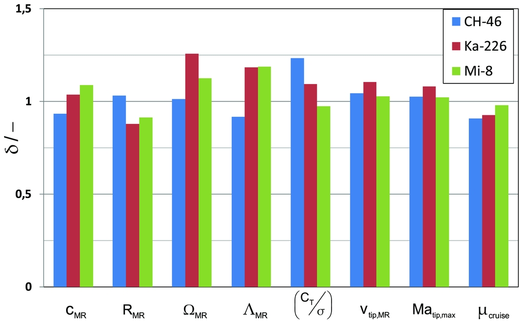
The process was started with the minimum of five TLARs for each configuration according to Table 1. Each run was started with the default constraints for the optimisation. Figure 14 shows for selected parameters the ratios of the designed to the reference values.
Parameter ratios for the rotors of the three reference helicopters (after the optimisation).

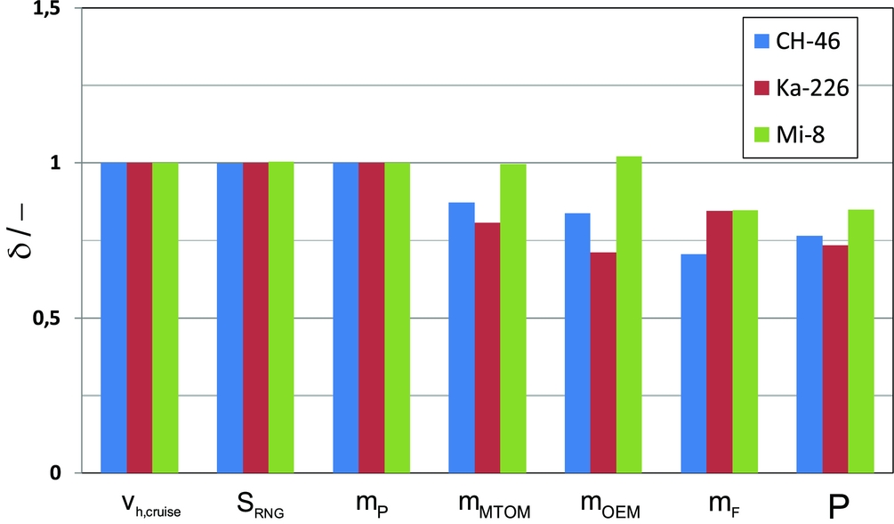
One crucial difference is that the blade loading of the tandem rotors (CH-46) design is about 23 % higher than the reference value. This leads to an absolute blade loading of 0.1. Another difference is the high rotational speed of the coaxial rotors (Ka-226) which is largely compensated by a smaller radius resulting in only a moderate increase of the tip speed. Further insight can be gained by examining the masses of the major components of the complete configuration. The ratios between the design study and the reference helicopters are shown in Fig. 15.
Parameter ratios for the overall configuration of the three reference helicopters (after the optimisation).

The range shown here is the result of the performance calculation with the required payload mass and flight speed. The calculation of the component masses is still not fully capable to take the customised drive train and propulsion system of a rotorcraft with more than one main rotor into account. The operating empty masses of the tandem and coaxial configurations are too low. Still not all sources of drag are implemented in the performance calculation and the influence of the subsystems is also not fully accounted for. The influence of the rotor hub is small and landing gear or skids and attachments are neglected. These influences result in a lower drag, a lower required power and consequently in a lower fuel mass.
The further computations by the Level 2 design tools, like the design of the structure, follows now, if requested by the user.
5.0 FURTHER COMPUTATIONS
The following paragraph deals with the implementation of Level 2 design tools into the process. As mentioned in the second paragraph, these tools have a significantly higher computational time and are not implemented in the scaling loop. Some examples of possible further computations are:
• Structural design
• Assessment of the crash behaviour
• Aerodynamic computation by free-wake model
• Noise level prediction
Before such tools are executed, the dataset is completed by the computation of additional parameters.
5.1 Computation of additional parameters
Succeeding the scaling loop, additional data are calculated in order to assess the designed configuration. Fast time simulations performed by HOST give information on the flight properties of the designed rotorcraft, in particular hints about mass and balance and about the rotor design and rotor arrangement. Typical calculations are payload/range diagrams and off-design conditions. HOST is also used to compute load cases in order to produce the input for the structural design analysis using finite element methods.
5.2 Structural design of the fuselage
Based on the scaled external configuration a more complex design of the internal structure can follow. The design tool for the structure is an autonomous process chain analysing and integrating the load carrying parts of the rotorcraft. The applied programs, which are connected via the CPACS format, originated in the fixed-wing aircraft design (see Scherer(Reference Scherer, Kohlgrüber, Dorbath and Sorour27)). They were adapted in order to work with the “rotorcraft” tree in the XML file. The computation time of the tool is far too long for the implementation in the scaling loop.
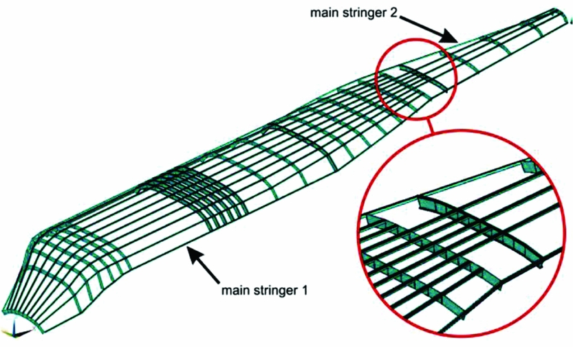
Starting point is the 3D-model created out of the generic fuselage during the scaling procedure. The model gives the outer boundary shape of the fuselage. The load-carrying structural parts of the fuselage, consisting primarily of spars and stringers and secondly of panels, are fitted into this shape. If necessary the pitch of the spars will be decreased. That can happen at all cut-outs like windows, doors or ramps, as well as at all points where major external forces are introduced by components like rotors or the gearbox, respectively, propellers, external payloads and so on. Windows, doors and ramps must be entered manually before the structural design is started. In addition to that, a very practicable feature, called stage modelling, is implemented. It can be used to adapt the primary structure's layout by interrupting or ending stringers. This is usually necessary in case of cut-outs or tapering of the fuselage. Fig. 16 shows an example of ending stringers at the junction between the fuselage body and the tail boom.
Reduction of the number of stringers at the connection to the tail boom.

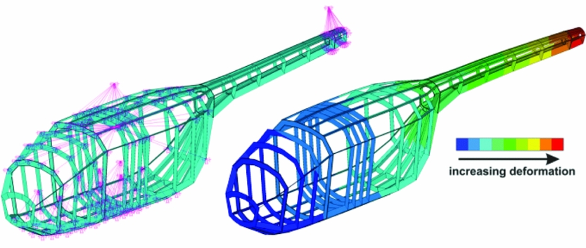
The generic layout of the structure is followed by a FEM (finite element method) calculation resulting from the manoeuvres and load cases, which have to be considered following the mission and certification requirements. Fig. 17 shows the result of an automatic layout of the primary structure in a generic fuselage dataset comparable to the example in Fig. 7. The smaller frame pitch at the longitudinal position of the main rotor, at the cockpit and at the rear of the fuselage body with the connection to the tail boom is well recognisable. The right side of Fig. 17 shows the corresponding deformations of the structure for cruise conditions. The influence of the surface panels is taken into account. But due to visibility, the panels are not displayed.
FE-model of the primary structure and structural deformations.

Following the FEM analysis flange and web of the primary structure are scaled according to the tolerable structural deflection. The result is a layout and mass estimation of the primary and secondary structures of the fuselage.
5.3 Rescaling
The deviations of such Level 2-recalculations from the results of the pure (Level 1-) scaling loop can be fed back to the scaling loop in order to rescale the design. The use of technology factors has shown to be very sensible in connection with the universal data model CPACS. A good example for the simple form of feedback from Level 2 to Level 1 is shown by the implementation of the tools for the structural mass and crash requirements (see Scherer(Reference Scherer, Kohlgrüber, Dorbath and Sorour27) and Schwinn(Reference Schwinn, Kohlgrüber, Scherer and Siemann28)). These tools recalculate the mass of the fuselage structure based on the results of the Level 1 loop and further requirements extending the previous boundaries as outlined above. The result is an updated component mass. The ratio of the Level 1 and Level 2 masses becomes the new technology factor for the component mass estimation in the scaling loop. This procedure is applicable to all component masses. It is an easy and very effective way to feedback results of Level 2, without integrating these higher fidelity and time demanding tools, into the level 1 scaling loop.
Besides rescaling due to the results of further analysis, changes can also be implemented according to the user's desires. For example wings and propellers could be added or changed resulting in a rescaling and a new assessment. As a result, given datasets can be easily modified and the adapted configuration may be simply compared with the previous configurations.
6.0 CONCLUSIONS
The presented process demonstrates a solution for a new integrated design environment. The design environment applies distributed computation including different levels of fidelity. The process is not hosted on one single server. The assessment and implementation of the computational tools in the process revealed new limitations and also new possibilities for the design toolbox. The most important results of the process reconstruction are:
• The more sophisticated calculation of the aerodynamic interference and component integration required for the design of future rotorcraft configurations will give a substantial feedback for the sizing of the external configuration.
• Not all levels of physical modelling can be covered in the primary sizing loop due to an uncontrolled expansion of the computation time. In contrast to the established process, a controlled freezing and unfreezing of the external configuration has to be performed between the Level 1 and Level 2 computations.
• The universal data-model CPACS allows the combination of workflows of different phases of design. Results of the preliminary design phase, which require a rescaling of the external configuration, can now be returned to the conceptual design phase in order to correct the previous configuration.
These features are required for the integrated design of new rotorcraft configurations like high-performance compound helicopters or aerial urban mobility vehicles showing complex interactions and difficult system integration. By breaking the borders between the levels of computation and phases of design, this integrated design environment will make such configurations scalable.
ACKNOWLEDGEMENTS
The authors thank Phillip Kunze for his support during the switchover to the new software framework. The works of Matthias Schmid on the calculation of the aerodynamic properties and Dominic Schwinn on the component mass estimation and generic structure are greatly appreciated.