1. Introduction
The study of oblique wave interactions with various types of vertical structures in single- or two-layer fluids is a critical aspect of ocean engineering and fluid mechanics. Breakwaters are primarily designed and used in coastal and ocean engineering to protect harbours, floating platforms and other marine structures from the impact of water waves. Their main function is to control wave height and forces. Flexible porous breakwaters are more effective than conventional rigid breakwaters due to their structural porosity and flexibility. These dual characteristics aid in dissipating substantial wave energy and enhance structural longevity by mitigating the adverse effects of oblique waves. Moreover, oblique waves cause non-uniform loading, leading to localised stress on the structure, and generate complex diffraction and refraction patterns, which complicate energy dissipation. The angled approach of these waves results in concentrated forces at specific points, further increasing the risk of structural damage. In this context, a flexible porous structure is a more viable option as a breakwater compared with rigid structures. Therefore, it is crucial for coastal engineering practice to accurately estimate the behaviour of flexible porous breakwaters when interacting with oblique waves in both single- and two-layer fluids.
In the existing literature, the two-dimensional free-surface scattering problem involving a submerged solid barrier was solved analytically by Dean (Reference Dean1945) by using the complex variable method. Subsequently, Ursell (Reference Ursell1947) obtained an analytical solution for the scattering problem involving a surface piercing solid barrier in a single-layer fluid. Porter (Reference Porter1972), Evans & Morris (Reference Evans and Morris1972), Porter & Evans (Reference Porter and Evans1995) and many others have made significant contributions to this field in the vertical rigid structures in the context of a single-layer fluid.
Later, flexible porous structures gained significant attention in a single-layer fluid. One of the pioneering contributions to this field was made by Chwang (Reference Chwang1983), who introduced the porous wave maker theory, incorporating the resistance effect. This theory was further expanded by Yu & Chwang (Reference Yu and Chwang1994), who included both inertial and resistance effects to establish boundary conditions for porous barriers. In the subsequent years, several researchers began to explore different configurations of flexible porous barriers, considering how incident waves interact with them. For instance, Lee & Chen (Reference Lee and Chen1990) studied the interaction of waves with a flexible barrier anchored at the surface and hinged at the seabed. Williams et al. (Reference Williams, Geiger and McDugal1991) and Williams (Reference Williams1993) used the boundary integral equation method to analyse the problem of a floating flexible breakwater consisting of a beam moored to the seabed and tensioned by a buoy at the surface, and extended the work to dual flexible breakwaters. Abul-Azm (Reference Abul-Azm1994) investigated the diffraction of a normal incident waves by dual impermeable flexible beam and demonstrated that the efficiency of elastic-plate breakwaters could be enhanced by tuning vertical plates. Meylan (Reference Meylan1995) tackled the scattering problem of a vertical surface-piercing flexible barrier in deep water using the Fredholm integral equation technique. Kim & Kee (Reference Kim and Kee1996) and Cho & Kim (Reference Cho and Kim1998) developed analytic and numerical solutions to wave interaction problems involving a horizontal tensioned flexible membrane by using the eigenfunction expansion method, while Cho & Kim (Reference Cho and Kim2000) used the multi-domain boundary element method to study horizontal porous flexible membranes. The study of wave interaction with vertical flexible membranes in finite water depths was also advanced by Lo (Reference Lo2000), while Lee & Lo (Reference Lee and Lo2002) explored the performance of single or dual surface-penetrating flexible membrane wave barriers. Sahoo et al. (Reference Sahoo, Yip and Chwang2001) expanded the understanding of wave interaction with a floating semi-infinite elastic plate in finite water depth, considering various edge conditions such as a free edge, a simply supported edge and a built-in edge.
Later, Behera & Sahoo (Reference Behera and Sahoo2015) addressed the wave scattering problem involving a submerged porous elastic plate by using an eigenfunction matching method. Mohapatra et al. (Reference Mohapatra, Sahoo and Soares2018) derived the long-wave equations under the shallow water approximation for the water-wave interaction with a submerged porous elastic plate, finding that wave energy dissipation is significantly influenced by factors such as mooring stiffness and the porous-effect parameter. Recent advancements include those by Meylan et al. (Reference Meylan, Bennetts and Peter2017), who developed both theoretical and numerical models for studying wave scattering by a floating porous elastic disk. This work was further extended by Koley et al. (Reference Koley, Mondal and Sahoo2018), who used the Fredholm integral equation technique to study oblique water-wave scattering by a floating flexible porous plate in infinite depth. Zheng et al. (Reference Zheng, Meylan, Fan, Greaves and Iglesias2020a ,Reference Zheng, Meylan, Greaves and Iglesias b ,Reference Zheng, Meylan, Zhu, Greaves and Iglesias c ) made significant strides in this field by developing a semi-analytical model based on linear potential flow theory and an eigenfunction expansion method to study wave scattering by a floating porous elastic plate of arbitrary shape, considering three different types of edge conditions, and extending the work to multiple submerged elastic disks and an array of floating circular porous elastic plates. Smith et al. (Reference Smith, Peter, Abrahams and Meylan2020) also investigated water-wave scattering by semi-infinite submerged thin elastic plates, considering both porous and non-porous materials using the Wiener–Hopf technique. Singh & Kaligatla (Reference Singh and Kaligatla2023) used the Galerkin eigenfunction expansion technique to study water-wave scattering by porous barriers in a vertical flexible-porous structure. They showed the flexible structure effect on Bragg resonance in the case of a rippled bottom. Ashok et al. (Reference Ashok, Gunasundari and Manam2020) derived a complete analytic solution for the scattering problems involving flexible porous barriers by making a novel connection among the wave potentials with the help of a weakly singular integral equation. Sasmal & De (Reference Sasmal and De2023) and Nandi et al. (Reference Nandi, Sarkar, Hossain and De2024) studied the effect of hydroelasticity on the surface gravity wave interaction with multiple poroelastic barriers in both infinite and finite depth water, and used the single-term Galerkin’s technique to determine that the structural rigidity of porous barriers plays an important role in reducing wave impact on barriers.
Although water-wave interaction with flexible porous structures has been widely studied in a single-layer fluid, negligible progress has been made in the context of two-layer fluids. Linton & McIver (Reference Linton and McIver1995) provided one of the earliest contributions in this domain by developing a general theory for wave-interaction problems involving horizontal cylinders in a two-layer fluid. Subsequent studies, such as those by Cadby & Linton (Reference Cadby and Linton2000) and Barthélemy et al. (Reference Barthélemy, Kabbaj and Germain2000), used the WKBJ method to analyse wave scattering in two-layer fluids. These studies provided valuable insights into reflection and transmission coefficients, expanding the theoretical framework for two-layer fluid interactions. Linton & Cadby (Reference Linton and Cadby2002) further explored oblique wave scattering by horizontal circular cylinders in a two-layer fluid using multipole expansions, while Chamberlain & Porter (Reference Chamberlain and Porter2005) used the variational principle to investigate wave scattering in a two-layer fluid with arbitrary bed undulations.
Some notable contributions to wave interaction with porous structures in a two-layer fluid can be found. For instance, Sherief et al. (Reference Sherief, Faltas and Saad2003) handled gravity waves generated by a porous wave maker in both finite and infinite depth water in a two-layer fluid by using Taylor’s assumption. Manam & Sahoo (Reference Manam and Sahoo2005) analysed wave motion past a porous structure in both cases of water of finite and infinite depths in a two-layer fluid under the assumption of linearised water wave theory, and they also derived unknown constants involved in the expansion formulae for the velocity potentials. Lin & Lu (Reference Lin and Lu2013) examined how obliquely incident waves affect the hydroelastic response of a semi-infinite thin floating elastic plate on a two-layer fluid having finite depth. Paul & De (Reference Paul and De2018) handled the problem of wave scattering by a thin vertical porous plate present in the upper layer of a two-layer fluid of finite depth, which was considered as the extension work solved by Dhillon et al. (Reference Dhillon, Banerjea and Mandal2014) for a solid plate. Behera et al. (Reference Behera, Mandal and Sahoo2013, Reference Behera, Koley and Sahoo2015) and Behera & Sahoo (Reference Behera and Sahoo2014) investigated the trapping of oblique waves by porous structures in various configurations in a two-layer fluid, employing eigenfunction expansion and Green’s function techniques. Also, approximation solution procedures were developed in the case of flexible permeable membranes in a two-layer fluid of finite depth. For example, Suresh Kumar et al. (Reference Suresh Kumar, Manam and Sahoo2007) studied the scattering of incident waves by a flexible porous membrane in a two-layer fluid by using the general orthogonal relation along with the least-squares approximation method. This work was extended by Mandal et al. (Reference Mandal, Behera and Sahoo2016) for multiple barriers in a two-layer fluid of finite depth. Behera et al. (Reference Behera, Ng and Sahoo2018) used the eigenfunction expansion method to solve the interaction of oblique waves with a floating elastic plate over a porous bed in a single- or two-layer fluid. Selvan & Behera (Reference Selvan and Behera2020) studied the effect of surface gravity waves on a floating circular flexible porous membrane in a single- or two-layer fluid with the help of the eigenfunction expansion method.
Over the past few decades, significant progress has been made in the study of wave interactions with elastic porous structures, particularly in single-layer fluid scenarios. However, further research is required to explore these interactions in two-layer fluids, especially in the context of oblique waves. While Suresh Kumar et al. (Reference Suresh Kumar, Manam and Sahoo2007) addressed the scattering problem of a flexible porous membrane in a two-layer fluid, this research only considered normally incident waves and finite depth water. Although an approximate solution was derived, explicit expressions for the essential hydrodynamic scattering quantities were not provided. The hydrodynamic interaction between oblique waves and elastic porous plate structures in a two-layer fluid is a critical area that remains underexplored. Also, there is a notable lack of analytical studies on wave interactions with various structures in two-layer fluids, especially considering both finite and infinite water depths. To the best of the authors’ knowledge, no comprehensive analytical research has yet been conducted to address the interaction of oblique waves with complete elastic porous structures in a two-layer fluid.
In this paper, a pair of novel integro-differential relations is established to figure out the complete analytical solution for the oblique wave scattering problem involving either an elastic porous plate or a permeable membrane in a two-layer fluid. The solution wave potentials are redefined in the quarter-plane. Each integro-differential relations serve as a connection between the solution wave potentials and auxiliary wave potentials. The auxiliary wave potential problems are solved analytically by using the generalised orthogonal relation. These two integro-differential relations are then employed to determine the required solution wave potentials. Additionally, explicit analytical expressions are derived for the scattering quantities, such as energy reflection and transmission, in both finite and infinite depth water. Moreover, the derived analytical results can act as a benchmark for other scattering problems involving other flexible structures.
The rest of this paper is organised as follows. First, the mathematical model for oblique wave scattering involving structures in a two-layer fluid is described in § 2. Sections 3 and 4 present the conversion from the half-plane problem into the quarter-plane problem, the establishment of novel connection and the solution procedure to derive the explicit analytical expression for hydrodynamic quantities as well as solution potentials. Moreover, in § 5, the behaviour of the energy reflection and transmission in both surface mode (SM) and interface mode (IM) are numerically investigated for different non-dimensional parameters of interest. Finally, the main outcomes of this work and further perspectives are presented in § 6.
2. Mathematical model
Under the assumption of the linearised water wave theory, the associated mixed boundary value problems are considered in a three-dimensional Cartesian coordinate system
 $(x, y, z)$
with the
 $y=0$
plane being the mean free surface and the positive
 $y$
-axis in the vertically downward direction. For a finite depth scenario, the upper fluid of constant density
 $\rho _1$
occupies the region
 $ 0 \lt y \lt h, -\infty \lt x,z\lt \infty$
, whilst the lower fluid of constant density
 $\rho _2$
occupies the region
 $h \lt y\lt H, -\infty \lt x,z\lt \infty$
with
 $y = h$
being the mean interface with
 $\rho _1\lt \rho _2$
. For the infinite depth case, the lower fluid stretches from
 $h$
to
 $\infty$
. As shown in figure 1, the flexible porous structures are positioned at
 $x=0$
, extending from the free surface to the bottom. The positions of the structures are indicated as
 $L_0$
and
 $L_{\infty }$
for finite and infinite depth water, respectively.
Schematic diagram of oblique wave interaction with flexible porous structures:
 $xy$
plane view.

The fluid is assumed to be inviscid and incompressible, with the motion of the fluid being irrotational. A simple harmonic wave is incident obliquely on the structure from the positive
 $x$
-axis, making an angle
 $\theta$
with the
 $xy$
plane. The resulting fluid motion is described by the time-harmonic wave potential
 $\Phi _1(x,y,z,t)= Re\{\phi _1(x,y)e^{\textrm {i}lz-\textrm {i}\omega t}\}$
, where
 $\textrm {i}=\sqrt {-1}, l=\lambda \sin {\theta }$
and
 $\lambda$
denotes the wavenumber which depends on the mode of the incident wave. Alternatively, the same wave motion can also be generated by waves incident on the same structure from the negative
 $x$
-axis, making an incident angle
 $\pi -\theta$
with the
 $xy$
plane and is described by the wave potential
 $\Phi _2(x,y,z,t)= Re\{\phi _2(x,y)e^{\textrm {i}lz+\textrm {i}\omega t}\}$
. The potentials
 $\Phi _1(x,y,z,t)\,\mbox {and}\, \Phi _2(x,y,z,t)$
have the phase difference
 $\frac {\pi }{2\omega }$
in time variable
 $t$
and
 $\frac {\pi }{2l}$
in the space variable
 $x$
. Then, the spatial velocity potentials
 $\phi _j(x,y), \,j=1,2$
, satisfy the modified Helmholtz equation in the fluid region
 \begin{align} (\nabla ^2 -l^2) \phi _j=0, \end{align}
along with the linearised free-surface boundary condition
 \begin{align} \Big(\frac {\partial }{\partial y} + K\Big )\phi _j=0 , \quad y=0, \end{align}
where
 $K = \frac {\omega ^2}{g}$
, with
 $g$
being the acceleration due to gravity, represents the normal incident wavenumber. The interface conditions are given by
 \begin{align} \frac {\partial \phi _j}{\partial y} \bigg |_{{y=h^-}} = \frac {\partial \phi _j}{\partial y}\bigg |_{y=h^+}, \end{align}
 \begin{align} s \left (\frac {\partial }{\partial y} +K \right )\phi _j \bigg |_{{y=h^-}}= \left (\frac {\partial }{\partial y} +K \right )\phi _j \bigg |_{y=h^+}, \end{align}
where
 $s=\frac {\rho _1}{\rho _2}$
. The bottom-boundary conditions are given by
 \begin{align} \frac {\partial \phi _j}{\partial y} =0 , \quad y=H \quad \mbox {for finite depth} \end{align}
and
 \begin{align} |\nabla \phi _j|\rightarrow 0 , \quad y\rightarrow \infty \quad \mbox {for infinite depth}, \end{align}
where
 $\nabla = (\frac {\partial }{\partial x}, \frac {\partial }{\partial y})$
. The radiation conditions for finite depth are given by
 \begin{align} \phi _j(x,y)\sim \begin{cases} \sum _{i=1}^{2} \left (I_i e^{-\textrm {i} \mu _i x} + R_i e^{\textrm {i} \mu _i x}\right ) g_0(m_i,y), & (-1)^{j+1}x\rightarrow \infty ,\\ \sum _{i=1}^{2} T_i e^{-\textrm {i} \mu _i x}g_0(m_i,y), & (-1)^{j+1}x\rightarrow -\infty , \end{cases}\quad j=1,2, \end{align}
where the unknown constants
 $R_i \,\mbox {and}\, T_i \,\mbox {for}\, i=1,2$
are the reflection and transmission coefficients in SM and IM, respectively, which are to be determined. The constants
 $I_i\,\mbox {for}\,i=1,2$
represent the incident wave amplitudes that are assumed to be known in SM and IM, respectively, and the parameters
 $\mu _i =m_i \cos {\theta },\,i=1,2$
. Also, the functions
 \begin{align} g_0(m_i,y) = \begin{cases} \sinh {m_i(h-H)}[m_i\cosh {m_i y}-K \sinh {m_i y}], & \,y \in (0,h),\\ [m_i\sinh {m_i h}-K\cosh {m_i h}] \cosh {m_i(y-H)}, & \,y \in (h,H), \end{cases}\quad i=1,2, \end{align}
in which
 $m_1 \,\text {and}\, m_2$
are the positive real roots of the following dispersion relation:
 \begin{align} (1-s) x^2 -K[\coth {x(H-h)}+\coth {xh}] + K^2 [s + \coth {x(H-h)}\coth {xh}] =0. \end{align}
A detailed description of the root behaviour can be found from Behera & Sahoo (Reference Behera and Sahoo2014). The eigenvalues
 $m_1$
and
 $m_2$
correspond to the wavenumbers of the incident waves in SM and IM, respectively. In the present analysis, two incident wave modes are considered at a time, hence without loss of generality; in all the present calculations,
 $\lambda$
is taken as
 $m_1$
for finite depth water (see Suresh Kumar et al. Reference Suresh Kumar, Manam and Sahoo2007).
Also, the radiation conditions for infinite depth are given by
 \begin{align} \begin{aligned}&\phi _j(x,y)\\ &{\sim}\! \begin{cases}\! I_1 e^{-\textrm {i} \kappa x-Ky} + I_2 e^{-\textrm {i} \mu x}q(y) +R_1 e^{\textrm {i} \kappa x-Ky}+ R_2 e^{\textrm {i} \mu x}q(y), &\!\!\! (-1)^{j+1}x\rightarrow \infty ,\\ \! T_1 e^{-\textrm {i} \kappa x-Ky}+ T_2 e^{-\textrm {i} \mu x}q(y), &\!\!\! (-1)^{j+1}x\rightarrow -\infty ,\end{cases} j=1,2, \end{aligned}\end{align}
where the parameters
 $ \kappa = K\cos {\theta },\,\mu = \nu \cos {\theta }$
and the functions
 \begin{align} q(y) = \begin{cases} \frac {K(1+ s )-\nu (1-s)} {\textit{2Ks}} e^{-\nu (y-h)}+ \frac {(K-\nu )( 1 - s )} {\textit{2Ks}} e^{\nu (y-h)}, & y \in (0,h),\\ e^{\nu (h-y)}, & y \in (h,\infty ), \end{cases} \end{align}
in which
 $\nu$
is the unique positive root of the following transcendental equation:
 \begin{align} [K(1+s)-\nu (1-s)] e^{\nu h}+ (K+\nu )( 1-s) e^{-\nu h}=0. \end{align}
In the above,
 $K$
and
 $\nu$
refer to the wavenumbers of the incident waves in SM and IM, respectively. For the infinite depth scenario, the
 $\lambda$
is taken as
 $K$
due to the same reason as mentioned for the finite depth case.
The displacement of the flexible porous structure is
 $\eta _j(y,t)=Re(\nu _j(y)e^{(-1)^j \textrm {i}\omega t}), j=1,2$
, in which complex deflection amplitude,
 $\nu _j, \,j=1,2$
, is considered to be a smallest absolute value. The boundary conditions on the structure in the fluid are given by (see Yu & Chwang Reference Yu and Chwang1994; Chwang & Chan Reference Chwang and Chan1998)
 \begin{align} \frac {\partial \phi _j}{\partial x}(0^\pm ,y)=(-1)^j\left [ \textrm {i} \lambda \Gamma \left ( \phi _j(0^+,y)-\phi _j(0^-,y) \right ) - \textrm {i}\omega \nu _j(y) \right ],\quad y\in L_0 \,\text {or}\, L_{\infty }, \end{align}
where
 $\Gamma =\Gamma _r + \textrm {i} \Gamma _i$
is the non-dimensional complex porous-effect parameter whose real part
 $\Gamma _r$
represents the resistance effect of the porous material against the seepage flow, while the imaginary part
 $\Gamma _i$
denotes the inertial effect of the fluid inside the material. This complex porous-effect parameter
 $\Gamma$
takes into account both the resistance and inertial effect of the porous structure in dissipating the wave energy.
We consider the vertical flexible porous structure as either a complete elastic porous plate or a flexible permeable membrane. The elastic porous plate is assumed to have uniform flexural rigidity
 $EI$
and uniform mass per unit length
 $m_p =\rho _p d_p$
, in which
 $\rho _p$
and
 $d_p$
are the plate’s uniform mass density and plate thickness, respectively. The deflection amplitudes
 $\nu _j(y), \,j=1,2$
for the elastic porous plate satisfies
 \begin{align} \left [\frac {\partial ^4}{\partial y^4} - \beta ^2\right ] \nu _j=\frac {\textrm {i}\omega \rho }{EI}\left [\phi _j(0^+,y)-\phi _j(0^-,y)\right ], \quad y\in L_0 \,\text {or}\, L_{\infty }, \quad j=1,2, \end{align}
where
 $\beta =\omega \sqrt {\frac {m_p}{EI}}$
and
 $\rho$
is the density of the fluid. The ends of the plate can be clamped or simply supported or allowed to be free with the mathematical conditions
 $\nu _j=\frac {\partial \nu _j}{\partial y}=0 \,\mbox {or}\, \nu _j=\frac {\partial ^2 \nu _j}{\partial y^2}=0\,\mbox {or}\, \frac {\partial ^2 \nu _j}{\partial y^2}=\frac {\partial ^3 \nu _j}{\partial y^3}=0$
at the end points, respectively. For a clamped plate, the displacement and slope at the edges are zero. The displacement and bending moments are zero when the plate edges are simply supported. The deflection, slope of deflection, bending moment and the shear force acting on the breakwater are continuous at the interface (see Yip et al. Reference Yip, Sahoo and Chwang2002), which yield the conditions
 $\frac {\partial ^n \nu _j}{\partial y^n} \big |_{y=h^-}=\frac {\partial ^n \nu _j}{\partial y^n}\big |_{y=h^+}, n=0,1,2,3.$
Eliminating
 $\nu _j(y), \,j=1,2$
, from (2.13) and (2.14), we obtain
 \begin{eqnarray} \left [\frac {\partial ^4}{\partial y^4} - \beta ^2\right ]\frac {\partial \phi _j}{\partial x}(0^\pm ,y) = (-1)^j \textrm {i} \lambda \Gamma \left [ \frac {\partial ^4 \phi _j}{\partial y^4}(0^+,y)-\frac {\partial ^4 \phi _j}{\partial y^4}(0^-,y)\right ] \nonumber \\ +(-1)^j \left (\frac {\rho }{m_p}-\textrm {i} \lambda \Gamma \right )\beta ^2 \left [\phi _j(0^+,y)-\phi _j(0^-,y)\right ],\quad j=1,2. \end{eqnarray}
Also, the flexible permeable membrane is assumed to be a thin, homogeneous and inextensible sheet under constant tension
 $T$
with uniform mass
 $m_s=\rho _sd_s$
, where
 $\rho _s$
and
 $d_s$
stand for membrane’s uniform mass density and its thickness. The deflection amplitudes
 $\nu _j(y), \,j=1,2$
for the flexible permeable membrane satisfy
 \begin{align} \left [\frac {\partial ^2}{\partial y^2} + \alpha ^2\right ] \nu _j=\frac {\textrm {i}\omega \rho }{T}\left [\phi _j(0^+,y)-\phi _j(0^-,y)\right ], \quad y\in L_0 \,\text {or}\, L_{\infty }, \quad j=1,2, \end{align}
where
 $\alpha =\omega \sqrt {\frac {m_s}{T}}$
is the membrane frequency parameter. In the case of the permeable membrane, the ends can be hinged and the mathematical conditions are translated
 $\nu _j=0$
at the end points. The continuity of the deflection and the slope of the membrane across the interface yield the conditions
 $\frac {\partial ^n \nu _j}{\partial y^n} \big |_{y=h^-}=\frac {\partial ^n \nu _j}{\partial y^n}\big |_{y=h^+},\, n=0,1.$
Eliminating
 $\nu _j(y), \,j=1,2$
, from (2.13) and (2.16), we obtain
 \begin{eqnarray} \left [\frac {\partial ^2}{\partial y^2} + \alpha ^2\right ]\frac {\partial \phi _j}{\partial x}(0^\pm ,y) = (-1)^j \textrm {i} \lambda \Gamma \left [ \frac {\partial ^2 \phi _j}{\partial y^2}(0^+,y)-\frac {\partial ^2 \phi _j}{\partial y^2}(0^-,y)\right ] \nonumber \\ +(-1)^j \left (\frac {\rho }{m_s}+\textrm {i} \lambda \Gamma \right )\alpha ^2 \left [\phi _j(0^+,y)-\phi _j(0^-,y)\right ],\quad j=1,2. \end{eqnarray}
3. Finite depth
The originally defined velocity potentials
 $\phi _j(x,y), \,j=1,2$
, in the upper-half plane may be transformed into new solution wave potential functions
 $\psi _j(x,y), \,j=1,2$
, in the quarter-plane due to the continuity of the fluid’s horizontal velocity across
 $x=0$
. This can be achieved by using the following special relation (see Lamb Reference Lamb1932):
 \begin{align} \phi _j(x,y)= \begin{cases} \sum _{i=1}^{2} \left ( e^{-\textrm {i} \mu _i x} + e^{\textrm {i} \mu _i x} \right ) g_0(m_i,y)+ \psi _j(x,y), & (-1)^{j+1}x\gt 0,\\ -\psi _j(-x,y), & (-1)^{j+1}x\lt 0, \end{cases} \quad j=1,2. \end{align}
Then, the new potential
 $\psi _j(x,y), \,j=1,2$
, is defined in the domain
 $(-1)^{j+1}x\gt 0, j=1,2$
, satisfying the conditions (2.1)–(2.5). The boundary conditions (2.15) and (2.17) are modified by making use of the above special relation (3.1) as
 \begin{align} &\left [\frac {\partial ^4}{\partial y^4} - \beta ^2\right ]\frac {\partial \psi _j}{\partial x}(0,y)+2 \textrm {i} m_1 \Gamma \left [\frac {\partial ^4 \psi _j}{\partial y^4}(0,y) +\sum _{i=1}^{2} m_i^4 g_0(m_i,y) \right ] \\ &\qquad \nonumber +2\beta ^2 \left (\frac {\rho }{m_p}- \textrm {i} m_1 \Gamma \right ) \left [ \psi _j(0,y) +\sum _{i=1}^{2} g_0(m_i,y) \right ] =0, \quad y\in L_0, \quad j=1,2, \end{align}
when the structure is the elastic porous plate and
 \begin{align} &\left [\frac {\partial ^2}{\partial y^2} + \alpha ^2\right ]\frac {\partial \psi _j}{\partial x}(0,y)+2 \textrm {i} m_1 \Gamma \left [\frac {\partial ^2 \psi _j}{\partial y^2}(0,y) +\sum _{i=1}^{2} m_i^2 g_0(m_i,y) \right ] \\ &\qquad \nonumber +2\alpha ^2 \left (\frac {\rho }{m_s}+ \textrm {i} m_1 \Gamma \right ) \left [ \psi _j(0,y) +\sum _{i=1}^{2} g_0(m_i,y) \right ] =0, \quad y\in L_0, \quad j=1,2, \end{align}
when the structure is the permeable membrane.
Finally, the radiation conditions for the new potential converted as
 \begin{eqnarray} \psi _j(x,y)\rightarrow \!\!\sum _{i=1}^{2}\!\! \left \{(I_i-1) e^{-\textrm {i} \mu _i x} + (R_i-1) e^{\textrm {i} \mu _i x}\right \} g_0(m_i,y), \ (-1)^{j+1}x\rightarrow \infty ,\ j=1,2,\nonumber \\ \end{eqnarray}
where the unknown constants
 $R_i, T_i , \,i=1,2$
, are correlated by
 $I_i - R_i= T_i,\,i=1,2.$
3.1. Elastic porous plate
To solve the mixed boundary value problem with higher-order structural boundary conditions, we must introduce a novel connection. A couple of integro-differential relations are introduced here to establish a connection between the elastic porous plate wave potentials
 $\psi _j(x,y), \,j=1,2$
, and the new auxiliary wave potentials
 $\chi _j(x,y),\,j=1,2$
. The newly involved auxiliary wave potentials describe the radiation of waves due to the vertical impermeable plate of the same configuration. These integro-differential relations help to decompose the original problem into resolvable boundary value problems for the auxiliary wave potentials. In what follows, this procedure is implemented for oblique wave scattering problems involving a complete elastic porous plate in a two-layer fluid.
3.1.1. Connection between wave potentials
Consider the connection between the wave potentials
 $\psi _j(x,y), \,j=1,2$
, and the new auxiliary wave potentials
 $\chi _j(x,y), \,j=1,2$
, as given by (see Mondal et al. Reference Mondal, Ashok and Manam2024)
 \begin{align} \left [\frac {\partial ^4}{\partial y^4} - \beta ^2\right ]\psi _j(x,y)+ \textrm {i} m_1 \Gamma \displaystyle \int _{0}^{x}\frac {\partial ^4 }{\partial y^4} \sigma _j(t, y)\,{\rm d}t +\beta ^2 \left (\frac {\rho }{m_p}- \textrm {i} m_1 \Gamma \right ) \displaystyle \int _{0}^{x} \sigma _j(t, y) {\rm d}t \nonumber \\ = \chi _j(x,y), (-1)^{j+1}x\gt 0, \quad j=1,2, \end{align}
where
 $ \sigma _j(t, y)= \sum _{i=1}^{2} \left \{ ( e^{-\textrm {i} \mu _i t} + e^{\textrm {i} \mu _i t} ) g_0(m_i,y) + \psi _i((-1)^{j+i} t, y) \right \}$
and the involved auxiliary wave potentials
 $\chi _j(x,y), j=1,2$
, satisfy (2.1)–(2.5). All the terms in the above well-defined connection (3.5) carry out the modified Helmholtz equation (2.1). The above integro-differential relation (3.5) is differentiated with respect to
 $x$
, we obtain that
 \begin{align} \left [\frac {\partial ^4}{\partial y^4} - \beta ^2 \right ] \psi _{jx}(x,y)+ \textrm {i} m_1 \Gamma \, \frac {\partial ^4 }{\partial y^4} \sigma _j(x, y) +\beta ^2 \left (\frac {\rho }{m_p}- \textrm {i} m_1 \Gamma \right ) \sigma _j(x, y) \nonumber \\ = \chi _{jx}(x,y), \,(-1)^{j+1}x\gt 0,\quad j=1,2. \end{align}
By putting
 $x=0$
in the abovementioned relation (3.6) along with the boundary condition (3.2), it may produce a Neumann type of structural boundary condition as
 \begin{align} \chi _{jx}(0,y)=0,\quad y\in L_0. \end{align}
Also,
 $\chi _j(x,y), \,j=1,2$
, satisfy the radiation condition
 \begin{align} \chi _j(x,y)\sim \sum _{i=1}^{2} \left ( \eta ^j_i e^{\textrm {i} \mu _i x} + \tau ^j_i e^{-\textrm {i} \mu _i x} \right ) g_0(m_i,y) , \quad (-1)^{j+1}x\rightarrow \infty , \end{align}
where
 $\eta ^j_i, \,\tau ^j_i, \,i=1,2$
, are unknown constants to be determined.
Using the radiation condition of each term in (3.6), we determine the unknown constants
 $\eta ^j_i, \,\tau ^j_i, \,i=1,2,\,j=1,2$
, as given by
 \begin{eqnarray} \eta _i^1 =\tau _i^2 &=& \left \{(1+\frac { m_1 \Gamma }{m_i} \sec {\theta } )(m_i^4-\beta ^2)-\frac {\textrm {i}\beta ^2 \rho _i}{m_i m_p} \sec {\theta } \right \} R_i \nonumber \\&+& \left \{\frac { m_1 \Gamma }{m_i} (m_i^4-\beta ^2)-\frac {\textrm {i}\beta ^2 \rho _i}{m_i m_p} \right \} \sec {\theta }\, (I_i-1)+ \beta ^2-m_i^4,\quad i=1,2\quad\, \end{eqnarray}
and
 \begin{eqnarray} \tau _i^1 =\eta _i^2 &=& \left \{\frac { m_1 \Gamma }{m_i} (\beta ^2 - m_i^4)+\frac {\textrm {i}\beta ^2 \rho _i}{m_i m_p} \right \} \sec {\theta } \,R_i \nonumber \\ &+&\left \{\big(1-\frac { m_1 \Gamma }{m_i} \sec {\theta } \big)(m_i^4-\beta ^2)+\frac {\textrm {i}\beta ^2 \rho _i}{m_i m_p} \sec {\theta } \right \} (I_i-1),\quad i=1,2.\quad\, \end{eqnarray}
3.1.2. Solution of wave potentials
The general solution of the auxiliary wave potential
 $\chi _j (x,y), \, y\in (0,H), \,j=1,2$
, which satisfies the modified Helmholtz equation (2.1) and the boundary conditions (2.2)–(2.5), (3.7) and (3.8) is given by
 \begin{align} \chi _j(x,y)&= \sum _{i=1}^{2} \left ( \eta ^j_i e^{\textrm {i} \mu _i x}+ \tau ^j_i e^{-\textrm {i} \mu _i x} \right )\,g_0(m_i,y)\nonumber \\ & + \sum _{n=1}^{\infty } A_n \,g_n(p_n,y) e^{(-1)^j \sqrt {p_n^2+l^2} \,x}, \,(-1)^{j+1}x\gt 0,\quad j=1,2, \end{align}
where
 $A_n,\, n= 1,2,\ldots$
, are unknown constants to be determined and the functions
 \begin{align} g_n(p_n,y) = \begin{cases} \sin {p_n(h-H)}[p_n\cos {p_n y}-K \sin {p_n y}], & \,y \in (0,h),\\ [p_n\sin {p_n h}+K\cos {p_n h}] \cos {p_n(y-H)}, & \,y \in (h,H), \end{cases} \quad n=1,2,\ldots \end{align}
in which
 $\textrm {i}p_n (p_n\gt 0), \, n= 1,2,\ldots$
, are purely imaginary roots of the dispersion relation (2.9), which support the evanescent waves.
It can be seen that the functions
 $g_n$
are the eigenfunctions associated with the self-adjoint linear differential operator
 $\frac {\partial ^2}{\partial y^2}$
corresponding to the eigenvalues
 $m_j^2,\,j=1,2$
, and
 $-p_n^2, \,n=1,2,\ldots$
, while satisfying the boundary conditions (2.2)–(2.5). These eigenfunctions
 $g_n$
are orthogonal with respect to the inner product defined by
 \begin{align} \langle g_n , g_m \rangle = s \displaystyle \int _{0}^{h} g_n(y)\,g_m(y) \,{\rm d}y + \int _{h}^{H} g_n(y)\,g_m(y) \,{\rm d}y . \end{align}
Further, using the above generalised orthogonal relation (3.5) on the Neumann type of structural boundary condition (3.7), we obtain that
 \begin{align} \eta _i^j =\tau _i^j, \quad j=1,2, \quad i=1,2 \end{align}
and
 \begin{align} A_n=0, \quad n=1,2,\ldots \end{align}
By using the linear expressions (3.9), (3.10) and (3.14), the reflection coefficients
 $R_i, i=1,2$
, can be obtained as
 \begin{align} R_i = \frac { \left \{ (1-\frac { 2 m_1 \Gamma }{m_i} \sec {\theta } )(m_i^4-\beta ^2)+\frac {2 \textrm {i}\beta ^2 \rho _i}{m_i m_p} \sec {\theta } \right \} (I_i-1) + m_i^4 -\beta ^2 }{(1+\frac { 2 m_1 \Gamma }{m_i} \sec {\theta } )(m_i^4-\beta ^2)-\frac {2 \textrm {i}\beta ^2 \rho _i}{m_i m_p} \sec {\theta } }, \quad i=1,2. \end{align}
In the limiting case,
 $I_i \rightarrow 1, \,i=1,2$
, and
 $\beta \rightarrow 0$
, the reflection and transmission coefficients are exactly matching with the result obtained by Manam & Sahoo (Reference Manam and Sahoo2005) for a porous plate in a two-layer fluid.
Moreover, the solution of the elastic porous plate wave potentials
 $\psi _j(x,y), j=1,2$
, can be obtained explicitly in terms of the auxiliary wave potentials
 $\chi _j(x, y), j=1,2$
, with the help of the connection (3.5). Then, by adding the two integro-differential relations (3.5), after writing them explicitly in the same domain
 $x \gt 0$
, and again by using the Laplace transform on
 $y$
variable along with the boundary conditions (2.2) and (2.5), one can obtain that
 \begin{eqnarray} \psi _1 (x,y)+\psi _2(-x, y)&=& \sum _{i=1}^{2} \frac {g_0(m_i,y) }{m_i^4-\beta ^2} \left [(\eta _i^1+\tau _i^2)e^{\textrm {i} \mu _i x}+(\tau _i^1+\eta _i^2)e^{-\textrm {i}\mu _i x}\right ] \nonumber \\ &+& 2 \sum _{i=1}^{2} \frac { A_n \,g_n(p_n,y) }{p_n^4-\beta ^2} e^{- \sqrt {p_n^2+l^2} x}. \end{eqnarray}
By putting the above result (3.17) into the connection (3.5) and again by the Laplace transform method, the solution wave potentials
 $\psi _j(x, y), j=1,2$
, for the elastic porous plate are obtained in an explicit form as given by
 \begin{eqnarray} &\psi _j& (x,y)\nonumber \\ &=& \sum _{i=1}^{2} \frac {g_0(m_i,y) }{m_i^4-\beta ^2} \Bigg [ \eta _i^j e^{ \textrm {i}\mu _i x}+\tau _i^j e^{-\textrm {i} \mu _i x}\Bigg ]+ \sum _{i=1}^{2} \Bigg [m_1 \Gamma -\frac {\textrm {i} \rho \beta ^2}{ m_p (m_i^4-\beta ^2)}\Bigg ] \frac {g_0(m_i,y) }{\mu _i}\nonumber \\ &&\Bigg [ - 2\textrm {i} \sin {\mu _i x} + \frac {(-1)^{j}}{m_i^4-\beta ^2}\Bigg \{ (\tau _i^1+\eta _i^2)(1-e^{(-1)^j \textrm {i} \mu _i x}) \nonumber \\ &+& ( \eta _i^1+ \tau _i^2)(e^{(-1)^{j+1} \textrm {i}\mu _i x}-1)\Bigg \}\Bigg ] + \sum _{n=1}^{\infty } \frac { A_n \,g_n(p_n,y) }{p_n^4-\beta ^2} \Bigg [e^{(-1)^j \sqrt {p_n^2+l^2} x} \nonumber \\&+& (-1)^j\frac {(1- e^{(-1)^j\sqrt {p_n^2+l^2} x})}{\sqrt {p_n^2+l^2}}\Big(2\textrm {i} m_1 \Gamma +\frac {2 \rho \beta ^2}{ m_p (p_n^4-\beta ^2)}\Big)\Bigg ],\ \ (-1)^{j+1} x\gt 0, \ \ j=1,2. \nonumber\\ && \end{eqnarray}
3.1.3. Deflection of the elastic porous plate
Furthermore, the relations (2.14) and (3.1) produce the following differential equations:
 \begin{eqnarray} &&\nonumber\left [\frac {\partial ^4}{\partial y^4} - \beta ^2 \right ] \nu _j(y)\\&& =(-1)^{j+1} \frac {2 \textrm {i} \omega \rho }{EI}\left [ \sum _{i=1}^{2} g_0(m_i,y) + \psi _1 (0,y) \right ],\quad y \in (0,H),\quad j=1,2, \end{eqnarray}
where
 \begin{eqnarray} \psi _1 (0,y) = \sum _{i=1}^{2} \frac {g_0(m_i,y) }{m_i^4-\beta ^2} (\eta _i^1 +\eta _i^2) + \sum _{n=1}^{\infty } \frac { A_n\, g_n(p_n,y) }{p_n^4-\beta ^2}, \end{eqnarray}
which can be found from (3.17) along with the observation
 $\psi _1 (0,y)= \psi _2(0, y)$
.
The above differential equation can be integrated and the deflection of the plate
 $\nu _j(y),\,j=1,2$
, can be determined as
 \begin{eqnarray} \nu _j(y)&= & C_1 \textrm {e}^{\sqrt {\beta }y}+ C_2 \textrm {e}^{-\sqrt {\beta }y}+ C_3 \textrm {e}^{\textrm {i}\sqrt {\beta }y}+ C_4 \textrm {e}^{-\textrm {i}\sqrt {\beta }y} +(-1)^{j+1} \frac {2 \textrm {i}\omega \rho }{EI}\left [ \sum _{i=1}^{2} \frac {g_0(m_i,y) }{ m_i^4-\beta ^2}\right. \nonumber \\ &+&\left.\sum _{i=1}^{2} \frac {g_0(m_i,y) }{ (m_i^4-\beta ^2)^2} (\eta _i^1 +\eta _i^2) + \sum _{n=1}^{\infty } \frac { A_n\,g_n(p_n,y) }{ (p_n^4-\beta ^2)^2} \right ] ,\quad y \in (0,H), \end{eqnarray}
where the unknown constants
 $C_i={\begin{cases} C_{i1}, & y\in (0,h)\\ C_{i2}, & y\in (h,H) \end{cases}}, \,i=1,2,3,4$
. The unknowns
 $C_{ij}, \, i=1,2,3,4, \,j=1,2$
, can be determined by applying the edge conditions of the plate and the interface conditions as discussed in § 2. The edge and interface conditions yield the necessary linear equations for the unknown constants.
3.2. Permeable membrane
When the structure is a permeable membrane, the connection between the permeable membrane wave potentials
 $\psi _j, \,j=1,2$
, and the new auxiliary wave potentials
 $\chi _j(x,y), \,j=1,2$
, is defined as (see Mondal et al. Reference Mondal, Ashok and Manam2024)
 \begin{align} & \left [\frac {\partial ^2}{\partial y^2} + \alpha ^2\right ]\psi _j(x,y) + \textrm {i} m_1 \Gamma \displaystyle \int _{0}^{x}\frac {\partial ^2 }{\partial y^2} \sigma _j(t, y)\,{\rm d}t +\alpha ^2 \left (\frac {\rho }{m_s}+ \textrm {i} m_1 \Gamma \right ) \displaystyle \int _{0}^{x} \sigma _j(t, y) {\rm d}t \nonumber\\ & \qquad\qquad\qquad\qquad\quad = \chi _j(x,y),\quad (-1)^{j+1}x \gt 0, \quad j=1,2, \end{align}
where the involved auxiliary potentials
 $\psi _j, j=1,2$
, satisfy (2.1)–(2.5) and each term in the well-defined integro-differential relation (3.22) carries out the modified Helmholtz equation (2.1). The above connection (3.22) is differentiated with respect to
 $x$
, we obtain that
 \begin{align} \left [\frac {\partial ^2}{\partial y^2} + \alpha ^2 \right ] \psi _{jx}(x,y)+ \textrm {i} m_1 \Gamma \, \frac {\partial ^2 }{\partial y^2} \sigma _j(x, y) +\alpha ^2 \left (\frac {\rho }{m_s}+ \textrm {i} m_1 \Gamma \right ) \sigma _j(x, y) \nonumber \\ = \chi _{jx}(x,y), \quad (-1)^{j+1}x\gt 0, \quad j=1,2. \end{align}
One can see that
 $\chi _j,\,j=1,2$
, satisfy (3.7) and the radiation condition (3.8).
After working out the problem for
 $\chi _j,\,j=1,2$
, by following the procedure as explained in § 3.1, the unknowns are obtained as
 \begin{eqnarray} \eta _i^1 =\tau _i^2 &=& \left \{(1+\frac { m_1 \Gamma }{m_i} \sec {\theta } )(m_i^2+\alpha ^2)-\frac {\textrm {i}\alpha ^2 \rho _i}{m_i m_s} \sec {\theta } \right \} R_i \nonumber \\&+& \left \{\frac { m_1 \Gamma }{m_i} (m_i^2+\alpha ^2)-\frac {\textrm {i}\alpha ^2 \rho _i}{m_i m_s} \right \} \sec {\theta }\, (I_i-1)- \alpha ^2-m_i^2, \quad i=1,2,\quad\, \end{eqnarray}
 \begin{eqnarray} \tau _i^1 =\eta _i^2 &=& \left \{-\frac { m_1 \Gamma }{m_i} (\alpha ^2 +m_i^2)+\frac {\textrm {i}\alpha ^2 \rho _2}{m_i m_s} \right \} \sec {\theta } \,R_i \nonumber \\ &+&\left \{(1-\frac { m_1 \Gamma }{m_i} \sec {\theta } )(m_i^2+\alpha ^2)+\frac {\textrm {i}\alpha ^2 \rho _2}{m_i m_s} \sec {\theta } \right \} (I_i-1), \quad i=1,2\quad\, \end{eqnarray}
and the unknown constants
 $A_n,\, n= 1,2,\ldots$
, satisfy (3.15). The reflection coefficients corresponding to the SM and IM can be obtained as
 \begin{align} R_i = \frac { \left \{ \Big(1-\frac { 2 m_1 \Gamma }{m_i} \sec {\theta } \Big)(m_i^2+\alpha ^2)+\frac {2 \textrm {i}\alpha ^2 \rho _i}{m_i m_s} \sec {\theta } \right \} (I_i-1) + m_i^2+\alpha ^2 }{\Big(1+\frac { 2 m_1 \Gamma }{m_i} \sec {\theta } \Big)(m_i^2+\alpha ^2)-\frac {2 \textrm {i}\alpha ^2 \rho _i}{m_i m_s} \sec {\theta } }, \quad i=1,2. \end{align}
The solution wave potentials
 $\psi _j(x, y), j=1,2$
, for the permeable membrane are derived explicitly as given by
 \begin{eqnarray} &&\nonumber\psi _j (x,y)\\ &&= \sum _{i=1}^{2} \frac {g_0(m_i,y) }{m_i^2+\alpha ^2} \left [ \eta _i^j e^{\textrm {i}\mu _i x}+\tau _i^j e^{-\textrm {i} \mu _i x}\right ]+ \sum _{i=1}^{2} \frac {g_0(m_i,y) }{\mu _i}\left [m_1 \Gamma -\frac {\textrm {i} \rho \alpha ^2}{ m_s (m_i^2+\alpha ^2)}\right ] \nonumber \\ &&\Bigg [ - 2\textrm {i} \sin {\mu _i x} + \frac {(-1)^{j}}{m_i^2+\alpha ^2}\Bigg \{ (\tau _i^1+\eta _i^2)(1-e^{(-1)^j \textrm {i} \mu _i x}) \nonumber \\ && + ( \eta _i^1+ \tau _i^2) (e^{(-1)^{j+1} \textrm {i}\mu _i x}-1)\Bigg \}\Bigg ] + \sum _{n=1}^{\infty } \frac { A_n g_n(p_n,y) }{p_n^2+\alpha ^2} \Bigg [e^{(-1)^j \sqrt {p_n^2+l^2} x} \nonumber \\&&+ (-1)^j\frac {(1- e^{(-1)^j\sqrt {p_n^2+l^2} x})}{\sqrt {p_n^2+l^2}}\Big(2\textrm {i} m_1 \Gamma +\frac {2 \rho \alpha ^2}{ m_s (p_n^2+\alpha ^2)}\Big)\Bigg ],\quad (-1)^{j+1} x\gt 0, \quad j=1,2. \nonumber \\ && \end{eqnarray}
Moreover, the deflection of the permeable membrane
 $\nu _j(y),\,j=1,2$
, is derived as
 \begin{eqnarray} \nu _j(y)&= & C_1 \cos {\alpha y}+ C_2 \sin {\alpha y}+(-1)^{j+1} \frac {2 \textrm {i}\omega \rho }{T}\left [ \sum _{i=1}^{2} \frac {g_0(m_i,y) }{ m_i^2+\alpha ^2}\right. \nonumber \\ &+&\left. \sum _{i=1}^{2} \frac {g_0(m_i,y) }{ (m_i^2+\alpha ^2)^2} (\eta _i^1 +\eta _i^2) + \sum _{n=1}^{\infty } \frac { A_n g_n(p_n,y) }{ (p_n^2+\alpha ^2)^2} \right ],\quad y \in (0, H), \end{eqnarray}
where the unknown constants
 $C_i={\begin{cases} C_{i1}, & y\in (0,h)\\ C_{i2}, & y\in (h,H) \end{cases}}, \,i=1,2$
. The unknowns
 $C_{ij}, i=1,2,\ j=1,2$
, can be determined by applying the edge conditions of the membrane and the interface conditions as discussed in § 2.
4. Infinite depth
The originally defined velocity potentials
 $\phi _j(x,y), \,j=1,2$
, in the upper-half plane may be transformed into new elastic porous plate wave potential functions
 $\psi _j(x,y), \,j=1,2$
, in the quarter-plane due to the continuity of the fluid’s horizontal velocity across
 $x=0$
. This can be done with the help of the following relation (see Lamb Reference Lamb1932):
 \begin{align} \begin{aligned}&\phi _j(x,y) \\ &\!= \!\begin{cases} e^{-\textrm {i} \kappa x-Ky} + e^{-\textrm {i} \mu x} q(y) + e^{\textrm {i} \kappa x-Ky} + e^{\textrm {i} \mu x} q(y)+ \psi _j(x,y),\! & (-1)^{j+1}x\gt 0,\\ -\psi _j(-x,y), & (-1)^{j+1}x\lt 0, \end{cases}\! \ j=1,2. \end{aligned}\end{align}
Then, the new potential
 $\psi _j(x,y), \,j=1,2$
, is defined in the domain
 $(-1)^{j+1}x\gt 0, j=1,2$
, satisfying the conditions (2.1)–(2.4), (2.6). The boundary conditions (2.15) and (2.17) are translated by using the above special relation (4.1) as
 \begin{align} &\left [\frac {\partial ^4}{\partial y^4} - \beta ^2\right ]\frac {\partial \psi _j}{\partial x}(0,y)+2 \textrm {i}K\Gamma \left [\frac {\partial ^4 \psi _j}{\partial y^4}(0,y) + K^4 e^{-Ky} +\nu ^4 q(y) \right ]\\ &+2\beta ^2 \left (\frac {\rho }{m_p}- \textrm {i}K \Gamma \right ) \left [ \psi _j(0,y) + e^{-Ky} + q(y) \right ] =0, \quad y\in L_{\infty }, \quad j=1,2,\nonumber \end{align}
when the structure is the elastic porous plate and
 \begin{align} &\left [\frac {\partial ^2}{\partial y^2} + \alpha ^2\right ]\frac {\partial \psi _j}{\partial x}(0,y)+2 \textrm {i} K \Gamma \left [\frac {\partial ^2 \psi _j}{\partial y^2}(0,y) + K^2 e^{-Ky} +\nu ^2 q(y) \right ] \nonumber \\ & +2\alpha ^2 \left (\frac {\rho }{m_s}+ \textrm {i} K\Gamma \right ) \left [ \varphi _j(0,y) + e^{-Ky} + q(y) \right ] =0, \quad y\in L_{\infty }, \quad j=1,2, \end{align}
when the structure is the permeable membrane. Further, the radiation conditions for the new potential transformed as
 \begin{eqnarray} \psi _j(x,y)\longrightarrow (I_1-1) e^{-\textrm {i} \kappa x-Ky} + (I_2-1)e^{-\textrm {i} \mu x}q(y) \nonumber\\ + (R_1-1) e^{\textrm {i} \kappa x-Ky}+ (R_2 -1) e^{\textrm {i} \mu x}q(y),\nonumber \\ \,(-1)^{j+1}x\rightarrow \infty , \quad j=1,2, \end{eqnarray}
where the constants
 $R_i, T_i , \,i=1,2$
, are correlated by
 $I_i - R_i= T_i,\,i=1,2.$
4.1. Elastic porous plate
4.1.1. Connection between wave potentials
Consider the connection between the wave potentials
 $\psi _j(x,y), \,j=1,2$
, and the new auxiliary wave potentials
 $\chi _j(x,y), \,j=1,2$
, as given by (see Mondal et al. Reference Mondal, Ashok and Manam2024)
 \begin{align} \left [\frac {\partial ^4}{\partial y^4} - \beta ^2\right ]\psi _j(x,y)+ \textrm {i}K\Gamma \displaystyle \int _{0}^{x}\frac {\partial ^4 }{\partial y^4} \sigma _j(t, y)\,{\rm d}t +\beta ^2 \left (\frac {\rho }{m_p}- \textrm {i}K\Gamma \right ) \displaystyle \int _{0}^{x} \sigma _j(t, y) {\rm d}t \quad\,\nonumber\\ = \chi _j(x,y), \quad (-1)^{j+1}x\gt 0,\quad j=1,2, \end{align}
where
 $ \sigma _j(t, y)= e^{\textrm {i} \kappa t-Ky} + e^{\textrm {i} \mu t}q(y) +e^{-\textrm {i} \kappa t-Ky} + e^{-\textrm {i} \mu t}q(y) + \sum _{i=1}^{2} \psi _i((-1)^{j+i} t, y)$
and the involved auxiliary wave potentials
 $\chi _j(x,y), j=1,2$
, satisfy (2.1)–(2.4) and (2.6). All the terms in the above-mentioned well-defined connection (4.5) carry out the modified Helmholtz equation (2.1). By differentiating (4.5) with respect to
 $x$
, it is obtained that
 \begin{align} \left [\frac {\partial ^4}{\partial y^4} - \beta ^2 \right ] \psi _{jx}(x,y)+ \textrm {i} K\Gamma \, \frac {\partial ^4 }{\partial y^4} \sigma _j(x, y) +\beta ^2 \left (\frac {\rho }{m_p}- \textrm {i} K\Gamma \right ) \sigma _j(x, y)\nonumber \\ = \chi _{jx}(x,y), \quad (-1)^{j+1}x\gt 0, \quad j=1,2. \end{align}
By setting
 $x=0$
in (4.6) along with the boundary condition (4.2), it may be obtained that
 \begin{align} \chi _{jx}(0,y)=0, \quad y\in L_{\infty }. \end{align}
Also,
 $\chi _j(x,y), \,j=1,2$
satisfy the radiation condition
 \begin{align} \chi _j(x,y)\sim \eta ^j_1 e^{\textrm {i} \kappa x-Ky}+ \tau ^j_1 e^{-\textrm {i} \kappa x-Ky}+ \eta ^j_2 e^{\textrm {i} \mu x}q(y) + \tau ^j_2e^{-\textrm {i} \mu x}q(y), \quad (-1)^{j+1}x\rightarrow \infty , \end{align}
where
 $\eta ^j_i, \,\tau ^j_i,\,i=1,2$
, are unknown constants.
Using the radiation condition of each term in the relation (4.6), we obtain the unknown constants
 $\eta ^j_i, \,\tau ^j_i,\,i=1,2,\,j=1,2$
, as given by
 \begin{eqnarray} \eta _1^1 =\tau _1^2 &=& \left \{(1+\Gamma \sec {\theta } )(K^4-\beta ^2)-\frac {\textrm {i}\beta ^2 \rho _1}{K m_p} \sec {\theta } \right \} R_1 \nonumber \\ &+& \left \{\Gamma (K^4-\beta ^2)-\frac {\textrm {i}\beta ^2 \rho _1}{K m_p} \right \}\sec {\theta } \,( I_1-1) +\beta ^2-K^4, \end{eqnarray}
 \begin{eqnarray} \tau _1^1 =\eta _1^2 &=& \left \{\Gamma (\beta ^2-K^4)+\frac {\textrm {i}\beta ^2 \rho _1}{K m_p} \right \} \sec {\theta } \,R_1 \nonumber \\ &+&\left \{(1-\Gamma \sec {\theta } )(K^4-\beta ^2)+\frac {\textrm {i}\beta ^2 \rho _1}{K m_p} \sec {\theta } \right \} ( I_1-1), \end{eqnarray}
 \begin{eqnarray} \eta _2^1 =\tau _2^2 &=& \left \{(1+\frac { K\Gamma }{\nu } \sec {\theta } )(\nu ^4-\beta ^2)-\frac {\textrm {i}\beta ^2 \rho _2}{\nu m_p} \sec {\theta } \right \} R_2 \nonumber\\&+& \left \{\frac { K\Gamma }{\nu } (\nu ^4-\beta ^2)-\frac {\textrm {i}\beta ^2 \rho _2}{\nu m_p} \right \} \sec {\theta }\,( I_2-1)+ \beta ^2-\nu ^4 \end{eqnarray}
and
 \begin{eqnarray} \tau _2^1 =\eta _2^2 &=& \left \{\frac { K\Gamma }{\nu } (\beta ^2 - \nu ^4)+\frac {\textrm {i}\beta ^2 \rho _2}{\nu m_p} \right \} \sec {\theta } \,R_2 \nonumber\\ &+&\left \{\Big(1-\frac { K\Gamma }{\nu } \sec {\theta } \Big)(\nu ^4-\beta ^2)+\frac {\textrm {i}\beta ^2 \rho _2}{\nu m_p} \sec {\theta } \right \}( I_2-1). \end{eqnarray}
4.1.2. Solution of wave potentials
The auxiliary wave potentials
 $\chi _j (x,y), \, y\in (0,\infty ), j=1,2$
, that satisfy modified Helmholtz equation (2.1) and the conditions (2.2)–(2.4), (2.6), (4.7) and (4.8) can be written as
 \begin{align} \chi _j(x,y)& = \eta ^j_1 e^{\textrm {i} \kappa x-Ky}+ \tau ^j_1 e^{-\textrm {i} \kappa x-Ky}+ \eta ^j_2 e^{\textrm {i} \mu x}q(y) + \tau ^j_2e^{-\textrm {i} \mu x}q(y) \\ &+ \displaystyle \int _{0}^{\infty } A(\xi ) \mathcal {L}(\xi ,y) e^{(-1)^j \sqrt {\xi ^2 +l^2} \, x} \,{\rm d}\xi ,\quad (-1)^{j+1}x\gt 0, \quad j=1,2, \nonumber \end{align}
where
 $A(\xi )$
is an unknown to be determined and
 \begin{align} \mathcal {L}(\xi ,y) = \begin{cases} K \,(\frac {\partial }{\partial y} -K) \sin {\xi y}, & y \in (0,h),\\ K \,(\frac {\partial }{\partial y} -K) \sin {\xi y} + (1-s) (\xi ^2 +K^2) \sin {\xi h} \cos {\xi (y-h)}, & y \in (h,\infty ). \end{cases} \end{align}
It may be seen that the functions
 $e^{-Ky}, q(y) \,\mbox {and}\, \mathcal {L}(\xi ,y)$
are the eigenfunctions associated with the self-adjoint linear differential operator
 $\frac {\partial ^2}{\partial y^2}$
corresponding to the eigenvalues
 $K^2, \nu ^2 \,\mbox {and}\, -\xi ^2 (\xi \gt 0)$
, while satisfying the boundary conditions (2.2), (2.3), (2.4) and (2.6). These eigenfunctions are orthogonal with respect to the inner product defined by
 \begin{align} \langle u(y) , v(y) \rangle = \lim _{\epsilon \to 0^+} \left [ s \displaystyle \int _{0}^{h} \displaystyle e^{-\epsilon y}\, u(y)\, v(y) \,{\rm d}y + \int _{h}^{\infty } e^{-\epsilon y}\, u(y)\, v(y) \,{\rm d}y \right ]. \end{align}
Further, using the above-mentioned orthogonal relation (4.15) on the Neumann type of boundary condition (4.7), we obtain that
 \begin{align} \eta _i^j =\tau _i^j , \quad j=1,2, \quad i=1,2 \end{align}
and
 \begin{align} A(\xi )=0. \end{align}
Furthermore, by using the linear expressions (4.9)–(4.12) and (4.16), the reflection coefficients in both SM and IM are derived as
 \begin{align} R_1 = \frac {\left \{(1-2\Gamma \sec {\theta } )(K^4-\beta ^2)+\frac {2\textrm {i}\beta ^2 \rho _1}{K m_p} \sec {\theta } \right \} (I_1-1) +K^4-\beta ^2}{(1+2\Gamma \sec {\theta } )(K^4-\beta ^2)-\frac {2\textrm {i}\beta ^2 \rho _1}{K m_p} \sec {\theta } } \end{align}
and
 \begin{align} R_2 = \frac { \left \{(1-\frac { 2K\Gamma }{\nu } \sec {\theta } )(\nu ^4-\beta ^2)+\frac {2\textrm {i}\beta ^2 \rho _2}{\nu m_p} \sec {\theta }\right \} (I_2-1) +\nu ^4-\beta ^2}{(1+\frac { 2K\Gamma }{\nu } \sec {\theta } )(\nu ^4-\beta ^2)-\frac {2\textrm {i}\beta ^2 \rho _2}{\nu m_p} \sec {\theta } }. \end{align}
In the limiting case,
 $I_i \rightarrow 1, \,i=1,2$
, and
 $\beta \rightarrow 0$
, the above hydrodynamic quantities obtained here are exactly matched with the result derived by Manam & Sahoo (Reference Manam and Sahoo2005) for a permeable plate in a two-layer fluid.
In a similar manner, elastic porous plate wave potentials
 $\psi _j(x, y),\,j=1,2$
, may be derived by following the solution procedure outlined in the § 3.1. Subsequently, the explicit analytical expressions for the velocity potentials
 $\psi _j(x, y),\,j=1,2$
, for infinite depth-water are obtained as
 \begin{eqnarray} &\psi _j& (x,y) \nonumber \\ &=& \frac {e^{-Ky} }{K^4-\beta ^2} \Big [ \eta _1^j e^{ \textrm {i}\kappa x}+\tau _1^j e^{-\textrm {i} \kappa x}\Big ]+ \frac {q(y) }{\nu ^4-\beta ^2} \Big [ \eta _2^j e^{ \textrm {i}\mu x}+\tau _2^j e^{-\textrm {i} \mu x}\Big ]\nonumber \\ &+& \frac {e^{-Ky} }{\kappa } \Big [K \Gamma -\frac {\textrm {i} \rho \beta ^2}{ m_p (K^4-\beta ^2)}\Big ] \Big [ - 2\textrm {i} \sin {\kappa x} + \frac {(-1)^{j}}{K^4-\beta ^2}\Big \{ (\tau _1^1+\eta _1^2)(1-e^{(-1)^j \textrm {i} \kappa x}) \nonumber \\ &+& ( \eta _1^1+ \tau _1^2)(e^{(-1)^{j+1} \textrm {i}\kappa x}-1)\Big \}\Big ] + \frac {q(y) }{\mu } \Big [K \Gamma -\frac {\textrm {i} \rho \beta ^2}{ m_p (\nu ^4-\beta ^2)}\Big ] \Big [ - 2\textrm {i} \sin {\mu x} \nonumber \\ &+& \frac {(-1)^{j}}{\nu ^4-\beta ^2}\Big \{ (\tau _2^1+\eta _2^2)(1-e^{(-1)^j \textrm {i} \mu x})+ ( \eta _2^1+ \tau _2^2)(e^{(-1)^{j+1} \textrm {i}\mu x}-1)\Big \}\Big ] \nonumber \\ &+& \displaystyle \int _{0}^{\infty } \frac { A(\xi ) \mathcal {L}(\xi ,y) }{\xi ^4-\beta ^2} \Big [e^{(-1)^j \sqrt {\xi ^2+l^2} x} \nonumber \\ &+& (-1)^j\frac {(1- e^{(-1)^j\sqrt {\xi ^2+l^2} x})}{\sqrt {\xi ^2+l^2}}\Big(2\textrm {i} K \Gamma +\frac {2 \rho \beta ^2}{ m_p (\xi ^4-\beta ^2)}\Big)\Big ] {\rm d}\xi ,\ \, (-1)^{j+1} x\gt 0, \ \, j=1,2. \nonumber\\ && \end{eqnarray}
Additionally, by following the similar procedure in § 3.1, the deflection amplitude of the elastic porous plate
 $\nu _j(y), j=1,2$
, for infinite depth-water can be derived as
 \begin{eqnarray} \nu _j(y) &= & C_1 \textrm {e}^{\sqrt {\beta }y}+ C_2 \textrm {e}^{-\sqrt {\beta }y}+ C_3 \textrm {e}^{\textrm {i}\sqrt {\beta }y}+ C_4 \textrm {e}^{-\textrm {i}\sqrt {\beta }y} \nonumber \\ && +(-1)^{j+1} \frac {2 \textrm {i}\omega \rho }{EI}\Bigg [ \frac {e^{-Ky} }{K^4-\beta ^2} + \frac {q(y) }{\nu ^4-\beta ^2} \nonumber \\ &&+ \frac {e^{-Ky} }{(K^4-\beta ^2)^2} ( \eta _1^1 +\eta _1^2 )+ \frac {q(y) }{(\nu ^4-\beta ^2)^2} ( \eta _2^1 +\eta _2^2 ) \nonumber \\ && + \displaystyle \int _{0}^{\infty } \frac { A(\xi ) \mathcal {L}(\xi ,y) }{(\xi ^4-\beta ^2)^2} {\rm d}\xi \Bigg ] ,\quad y \in (0,\infty ), \end{eqnarray}
where the unknown constants
 $C_i={\begin{cases} C_{i1}, & y\in (0,h)\\ C_{i2}, & y\in (h,\infty ) \end{cases}}, \,i=1,2,3,4$
. The unknown constants
 $C_{12} \,\mbox {and}\, C_{32}$
must be zero; otherwise, the functions
 $\nu _j(y)$
become unbounded as
 $y\rightarrow \infty$
. The edge and interface conditions yield the necessary linear equations for the remaining unknown constants.
4.2. Permeable membrane
The connection between the permeable membrane wave potentials
 $\psi _j, \,j=1,2$
, and the new auxiliary wave potentials
 $\chi _j(x,y), \,j=1,2$
, can be defined as (see Mondal et al. Reference Mondal, Ashok and Manam2024)
 \begin{align} \left [\frac {\partial ^2}{\partial y^2} + \alpha ^2\right ]\psi _j(x,y)+ \textrm {i}K\Gamma \displaystyle \int _{0}^{x}\frac {\partial ^2 }{\partial y^2} \sigma _j(t, y)\,{\rm d}t +\alpha ^2 \left (\frac {\rho }{m_s}+ \textrm {i}K\Gamma \right ) \displaystyle \int _{0}^{x} \sigma _j(t, y) {\rm d}t \quad\,\nonumber \\ = \chi _j(x,y), \quad (-1)^{j+1}x\gt 0, \quad j=1,2, \end{align}
where the involved auxiliary potentials
 $\chi _j, j=1,2$
, satisfy (2.1)–(2.4) and (2.6). All the terms in well-defined relation (4.22) carry out the modified Helmholtz equation (2.1). The connection (4.22) is differentiated with respect to
 $x$
, we obtain that
 \begin{align} \left [\frac {\partial ^2}{\partial y^2} + \alpha ^2 \right ] \psi _{jx}(x,y)+ \textrm {i} K\Gamma \, \frac {\partial ^2 }{\partial y^2} \sigma _j(x, y) +\alpha ^2 \left (\frac {\rho }{m_s}+ \textrm {i} K\Gamma \right ) \sigma _j(x, y)\nonumber \\ = \chi _{jx}(x,y), \quad (-1)^{j+1}x\gt 0, \quad j=1,2. \end{align}
One can see that
 $\chi _j,\,j=1,2$
, satisfy (4.7) and the radiation condition (4.8).
After working out the problem for
 $\chi _j,\,j=1,2$
, by following the procedure as explained in § 4.1, the unknowns are obtained as
 \begin{eqnarray} \eta _1^1 =\tau _1^2 &=& \left \{(1+\Gamma \sec {\theta } )(K^2+\alpha ^2)-\frac {\textrm {i}\alpha ^2 \rho _1}{K m_s} \sec {\theta } \right \} R_1 \nonumber \\&+& \left \{\Gamma (K^2+\alpha ^2)-\frac {\textrm {i}\alpha ^2 \rho _1}{K m_s} \right \}\sec {\theta } \,( I_1-1) -\alpha ^2-K^2, \end{eqnarray}
 \begin{eqnarray} \tau _1^1 =\eta _1^2 &=& \left \{-\Gamma (\alpha ^2+K^2)+\frac {\textrm {i}\alpha ^2 \rho _1}{K m_s} \right \} \sec {\theta } \,R_1 \nonumber \\ &+&\left \{(1-\Gamma \sec {\theta } )(K^2+\alpha ^2)+\frac {\textrm {i}\alpha ^2 \rho _1}{K m_s} \sec {\theta } \right \} ( I_1-1), \end{eqnarray}
 \begin{eqnarray} \eta _2^1 =\tau _2^2 &=& \left \{(1+\frac { K\Gamma }{\nu } \sec {\theta } )(\nu ^2+\alpha ^2)-\frac {\textrm {i}\alpha ^2 \rho _2}{\nu m_s} \sec {\theta } \right \} R_2 \nonumber \\&+& \left \{\frac { K\Gamma }{\nu } (\nu ^2+\alpha ^2)-\frac {\textrm {i}\alpha ^2 \rho _2}{\nu m_s} \right \} \sec {\theta }\,( I_2-1)- \alpha ^2-\nu ^2, \end{eqnarray}
 \begin{eqnarray} \tau _2^1 =\eta _2^2 &=& \left \{-\frac { K\Gamma }{\nu } (\alpha ^2 + \nu ^2)+\frac {\textrm {i}\alpha ^2 \rho _2}{\nu m_s} \right \} \sec {\theta } \,R_2 \nonumber \\ &+&\left \{\Big(1-\frac { K\Gamma }{\nu } \sec {\theta } \Big)(\nu ^2+\alpha ^2)+\frac {\textrm {i}\alpha ^2 \rho _2}{\nu m_s} \sec {\theta } \right \}( I_2-1) \end{eqnarray}
and the unknown constant
 $A(\xi )$
satisfies (3.15). The reflection coefficients in SM and IM are derived as
 \begin{align} R_1 = \frac {\left \{(1-2\Gamma \sec {\theta } )(K^2+\alpha ^2)+\frac {2\textrm {i}\alpha ^2 \rho _1}{K m_s} \sec {\theta } \right \} (I_1-1) +K^2+\alpha ^2}{(1+2\Gamma \sec {\theta } )(K^2+\alpha ^2)-\frac {2\textrm {i}\alpha ^2 \rho _1}{K m_s} \sec {\theta } } \end{align}
and
 \begin{align} R_2 = \frac { \left \{(1-\frac { 2K\Gamma }{\nu } \sec {\theta } )(\nu ^2+\alpha ^2)+\frac {2\textrm {i}\alpha ^2 \rho _2}{\nu m_s} \sec {\theta }\right \} (I_2-1) +\nu ^2+\alpha ^2}{(1+\frac { 2K\Gamma }{\nu } \sec {\theta } )(\nu ^2+\alpha ^2)-\frac {2\textrm {i}\alpha ^2 \rho _2}{\nu m_s} \sec {\theta } }. \end{align}
The velocity potentials
 $\psi _j(x, y),\,j=1,2$
, for a permeable membrane in deep water are obtained explicitly as
 \begin{eqnarray} &\psi _j& (x,y) \nonumber\\ &=& \frac {e^{-Ky} }{K^2+\alpha ^2} \left [ \eta _1^j e^{ \textrm {i}\kappa x}+\tau _1^j e^{-\textrm {i} \kappa x}\right ]+ \frac {q(y) }{\nu ^2+\alpha ^2} \left [ \eta _2^j e^{\textrm {i}\mu x}+\tau _2^j e^{-\textrm {i} \mu x}\right ]\nonumber \\ &+& \frac {e^{-Ky} }{\kappa } \left [K \Gamma -\frac {\textrm {i} \rho \alpha ^2}{ m_s (K^2+\alpha ^2)}\right ] \left [ - 2\textrm {i} \sin {\kappa x} + \frac {(-1)^{j}}{K^2+\alpha ^2}\left \{ (\tau _1^1+\eta _1^2)(1-e^{(-1)^j \textrm {i} \kappa x})\right.\right. \nonumber \\ &+& \left. \left. ( \eta _1^1+ \tau _1^2)(e^{(-1)^{j+1} \textrm {i}\kappa x}-1)\right \}\right ] + \frac {q(y) }{\mu } \left [K \Gamma -\frac {\textrm {i} \rho \alpha ^2}{ m_s (\nu ^2+\alpha ^2)}\right ] \left [ - 2\textrm {i} \sin {\mu x} \right. \nonumber \\ &+& \left.\frac {(-1)^{j}}{\nu ^2+\alpha ^2}\left \{ (\tau _2^1+\eta _2^2)(1-e^{(-1)^j \textrm {i} \mu x})+ ( \eta _2^1+ \tau _2^2)(e^{(-1)^{j+1} \textrm {i}\mu x}-1)\right \}\right ] \nonumber \\ &+& \displaystyle \int _{0}^{\infty } \frac { A(\xi ) \mathcal {L}(\xi ,y) }{\xi ^2+\alpha ^2} \Bigg [e^{(-1)^j \sqrt {\xi ^2+l^2} x} \nonumber \\ &+& (-1)^j\frac {(1- e^{(-1)^j\sqrt {\xi ^2+l^2} x})}{\sqrt {\xi ^2+l^2}}\Big(2\textrm {i} K \Gamma +\frac {2 \rho \alpha ^2}{ m_s (\xi ^2+\alpha ^2)}\Big)\Bigg ] {\rm d}\xi ,\ \ (-1)^{j+1} x\gt 0, \ \ j=1,2. \nonumber \\ &&\end{eqnarray}
Additionally, by following the similar procedure in § 3.1, the deflection amplitude of the permeable membrane
 $\nu _j(y), j=1,2$
, in deep water can be derived as
 \begin{eqnarray} \nu _j(y) &= & C_1 \textrm {e}^{\textrm {i}\alpha y}+ C_2 \textrm {e}^{-\textrm {i}\alpha y} \nonumber\\ &+&(-1)^{j+1} \frac {2 \textrm {i}\omega \rho }{T}\left [ \frac {e^{-Ky} }{K^2+\alpha ^2} + \frac {q(y) }{\nu ^2+\alpha ^2} + \frac {e^{-Ky} }{(K^2+\alpha ^2)^2} ( \eta _1^1 +\eta _1^2 )\right. \\ &+& \left.\frac {q(y) }{(\nu ^2+\alpha ^2)^2} ( \eta _2^1 +\eta _2^2 ) + \displaystyle \int _{0}^{\infty } \frac { A(\xi ) \mathcal {L}(\xi ,y) }{(\xi ^2+\alpha ^2)^2} {\rm d}\xi \right ] ,\quad y \in (0,\infty ), \nonumber \end{eqnarray}
where the unknown constants
 $C_i={\begin{cases} C_{i1}, & y\in (0,h)\\ C_{i2}, & y\in (h,\infty ) \end{cases}}, \,i=1,2$
. The unknown constant
 $C_{12}$
must be zero; otherwise, the functions
 $\nu _j(y)$
become unbounded as
 $y\rightarrow \infty$
. The edge and interface conditions yield the necessary linear equations for the remaining unknown constants.
5. Numerical analysis
Numerical results are presented for the energy reflection and transmission against a non-dimensional wavenumber and the angle of incidence. The dimensionless parameters considered include plate mass
 $\delta =\frac {m_p}{\rho _2 h}$
, membrane mass
 $\delta _1=\frac {m_s}{\rho _2 h}$
, plate flexural rigidity
 $\epsilon =\frac {EI}{\rho _2 g h^4}$
and membrane tension
 $ \epsilon _1=\frac {T}{\rho _2 g h^2}$
, where
 $\rho _2 = 1025\, \mathrm {kg}\,{\rm m^-{^3}}$
. The known constant
 $I_i,\,i=1,2$
is taken as unity.
The magnitude of the horizontal hydrodynamic force acting on the vertical flexible porous structure, indicated by
 $B_j,\,j=1,2$
, is derived by making use of the formula (see Behera & Sahoo Reference Behera and Sahoo2014)
 \begin{eqnarray} B_j=\textrm {i} \rho \omega \int _{L_0 \,\mbox {or}\, L_{\infty }} \left (\phi _j(0^+,y)-\phi _j(0^-,y) \right )\,{\rm d}y,\quad j=1,2, \end{eqnarray}
where the appropriate value of
 $\rho$
is taken based on the physical nature of the problem.
5.1. Finite depth
In this subsection, the reflection and transmission curves in the SM and IM are plotted against the wavenumber
 $m_1H$
and the angle of incidence
 $\theta$
. These curves are presented for different values of the non-dimensional parameter, including porous effect parameter
 $\Gamma$
, fluid depth ratio
 $h/H$
, fluid density ratio
 $s$
, plate flexural rigidity
 $\epsilon$
and membrane tension
 $\epsilon _1$
. The dimensionless form of the horizontal hydrodynamic force coefficient on the vertical flexible porous structure for finite depth water is given by
 \begin{eqnarray} F_j=\frac {|B_j|}{\rho _2 g h H},\quad j=1,2, \end{eqnarray}
where
 \begin{eqnarray} B_j=\textrm {i} \rho \omega \int _{0}^{H} \left (\sum _{i=1}^{2} g_0(m_i,y) + \psi _j (0,y) \right )\,{\rm d}y. \end{eqnarray}
5.1.1. Elastic porous plate
 $|R_1|$
and
 $|T_1|$
plotted against
 $m_1H$
for different values of
 $\Gamma$
when
 $\theta =\pi /3$
,
 $s=0.5$
,
 $h/H=0.5$
,
 $\epsilon =0.01$
and
 $\delta =2$
.

In figures 2 and 3, the reflection and transmission curves in both SM and IM are plotted against the wavenumber
 $m_1H$
by fixing
 $\theta =\pi /3$
,
 $s=0.5$
,
 $h/H=0.5$
,
 $\epsilon =0.01$
and
 $\delta =3$
. It is observed from figure 2 that the reflection curves in SM increase monotonically from a smaller wavenumber to a certain value and then stabilise at a constant value for moderate and higher wavenumbers across all permeable elastic plates. In contrast, the reflection curve for the impermeable elastic plate (
 $\Gamma =0$
) increases monotonically for all wavenumbers. The transmission curves exhibit the opposite trend. Figure 3 illustrates that reflection curves initially increase then converge to a zero, and thereafter they increase before stabilising at a constant level. Notably, the reflection curve for the impermeable elastic plate is unity for certain wavenumbers as the plate frequency parameter (
 $\beta$
) approaches zero. The transmission curves follow the reverse pattern. Figures 2 and 3 also reveal that the reflection curves in both SM and IM decrease as the inertial and resistive effects of the porous parameter increase, while a reverse trend is observed for wave transmission. This behaviour is intuitively expected, as an increase in porosity allows more waves to pass through while simultaneously reducing the plate’s resistance to wave motion. Similar results are obtained for wave reflection by an elastic porous plate in a single-layer fluid by Koley et al. (Reference Koley, Kaligatla and Sahoo2015). Breakwater without porosity exhibits higher wave reflection and lower wave transmission. This observation may be useful in the design and development of wave energy converters.
 $|R_2|$
and
 $|T_2|$
plotted against
 $m_1H$
for different values of
 $\Gamma$
when
 $\theta =\pi /3$
,
 $s=0.5$
,
 $h/H=0.5$
,
 $\epsilon =0.1$
and
 $\delta =2$
.

 $|R_1|$
and
 $|T_1|$
plotted against
 $\theta$
for different values of
 $\Gamma$
when
 $s=0.5$
,
 $h/H=0.5$
,
 $\epsilon =0.01$
and
 $\delta =2$
.

 $|R_2|$
and
 $|T_2|$
plotted against
 $\theta$
for different values of
 $\Gamma$
when
 $s=0.5$
,
 $h/H=0.5$
,
 $\epsilon =0.01$
and
 $\delta =2$
.

Reflection and transmission curves are plotted against the angle of incidence for various values of the porous effect parameter
 $\Gamma$
when the values of
 $s=0.5$
,
 $h/H=0.5$
,
 $\epsilon =0.01$
and
 $\delta =2$
are fixed in figures 4 and 5. Reflection curves in both SM and IM increase gradually with a decrease in the angle of incidence for all the porous effect parameters. Also, enhanced reflection is noted for both SM and IM when the permeable plate becomes impermeable and approaches unity as the plate frequency parameter goes to zero. Wave reflection and transmission are notable for smaller incidence of angle. Furthermore, negligible energy reflection and full energy transmission are observed in both SM and IM for incident waves with angles closer to
 $ 90^\circ$
, as expected, since waves do not pass through the porous structure.
In figures 6 and 7, the energy reflection and transmission are depicted against the wavenumber
 $m_1H$
for different values of the flexural rigidity parameter
 $\epsilon$
by fixing
 $\theta =\pi /3$
,
 $\Gamma =1$
,
 $s=0.5$
,
 $h/H=0.5$
and
 $\delta =2$
. As depicted in figures 6 and 7, the energy reflection curves exhibit a resonant minimum within a certain range of wavenumbers, while the energy transmission curves reach a resonant maximum within the same range for all flexural rigidity parameters. In SM, the reflection and transmission curves exhibit a resonant minimum and maximum, respectively, within the range of wavenumber
 $2.5\lt m_1 H\lt 4.5$
, whereas in IM, the corresponding wavenumber range is
 $1\lt m_1 H\lt 2.5$
. A plate exhibiting lower stiffness is found to generate waves with higher wave transmission and lower wave reflection. In a real scenario, reflected waves from breakwaters are often required to be minimised to reduce the occurrence of wave resonance, particularly within the harbour area. In such scenarios, elastic porous structures can be effectively used to reduce both transmitted and reflected wave heights.
 $|R_1|$
and
 $|T_1|$
plotted against
 $m_1H$
for different values of
 $\epsilon$
when
 $\theta =\pi /3$
,
 $\Gamma =1$
,
 $s=0.5$
,
 $h/H=0.5$
and
 $\delta =2$
.

 $|R_2|$
and
 $|T_2|$
plotted against
 $m_1H$
for different values of
 $\epsilon$
when
 $\theta =\pi /3$
,
 $\Gamma =1$
,
 $s=0.5$
,
 $h/H=0.5$
and
 $\delta =2$
.

 $|R_1|$
and
 $|T_1|$
plotted against
 $\theta$
for different values of
 $\epsilon$
when
 $\Gamma =1$
,
 $s=0.5$
,
 $h/H=0.5$
and
 $\delta =2$
.

In figures 8 and 9, reflection energy and transmission energy curves are depicted in both SM and IM against the angle of oblique wave incidence
 $\theta$
for different values of non-dimensional flexural rigidity parameter
 $\epsilon$
while
 $\Gamma =1$
,
 $s=0.5$
,
 $h/H=0.5$
and
 $\delta =2$
are fixed. Figures 8 and 9 demonstrate that the reflection curves exhibit a monotonically decreasing trend as the oblique angle increases, regardless of the flexural rigidity parameter values, while the transmission curves follow the reverse pattern. A plate with higher flexural rigidity produces lower wave reflection and higher wave transmission. It is expected that in both SM and IM, the enhanced reflection curve for
 $\epsilon = 0.05$
is higher than the other curves, as the elastic porous plate behaves like a rigid porous plate at this value.
 $|R_2|$
and
 $|T_2|$
plotted against
 $\theta$
for different values of
 $\epsilon$
when
 $\Gamma =1$
,
 $s=0.5$
,
 $h/H=0.5$
and
 $\delta =2$
.

 $|R_1|$
and
 $|T_1|$
plotted against
 $m_1H$
for different values of
 $h/H$
when
 $\theta =\pi /3$
,
 $\Gamma =1$
,
 $s=0.5$
,
 $\epsilon =0.01$
and
 $\delta =2$
.

 $|R_2|$
and
 $|T_2|$
plotted against
 $m_1H$
for different values of
 $h/H$
when
 $\theta =\pi /3$
,
 $\Gamma =1$
,
 $s=0.5$
,
 $\epsilon =0.01$
and
 $\delta =2$
.

 $|R_2|$
and
 $|T_2|$
plotted against
 $m_1H$
for different values of
 $s$
when
 $\theta =\pi /3$
,
 $\Gamma =1$
,
 $h/H=0.5$
,
 $\epsilon =0.01$
and
 $\delta =2$
.

Reflection and transmission curves are plotted, in figures 10 and 11, against wavenumber
 $m_1H$
for different
 $h/H$
in both SM and IM when
 $\theta =\pi /3$
,
 $\Gamma =1$
,
 $s=0.5$
,
 $\epsilon =0.01$
and
 $\delta =2$
are fixed. Figure 10 demonstrates that wave reflection is higher when both layers have almost equal depths, i.e.
 $h/H = 0.9$
, and reflection is lower for a thinner upper layer, such as at
 $h/H = 0.1$
, almost over the entire range of interest. This phenomenon arises due to the resonant interaction between surface and internal waves when the free surface is close to the interface. However, in IM, the energy reflection curves exhibit a resonant minimum within a range of wavenumber
 $1\lt m_1H\lt 3$
, while the energy transmission curves reach a resonant maximum within the same wavenumber range for all fluid depth ratio parameters.
In figure 12, reflection and transmission curves are plotted in SM against wavenumber
 $m_1H$
for different values of fluid density ratio
 $s$
while
 $\theta =\pi /3$
,
 $\Gamma =1$
,
 $h/H=0.5$
,
 $\epsilon =0.01$
and
 $\delta =2$
are fixed. For waves in IM, the reflection curves increase with an increase in the fluid density ratio, while the transmission curves exhibit an inverse trend. Furthermore, it is notably observed that the reflection curve for
 $s=0.9$
is significantly higher than other curves as the fluid density ratio approaches unity.
 $|R_1|$
and
 $|T_1|$
plotted against
 $\theta$
for different values of
 $s$
when
 $\Gamma =1+\textrm {i}$
,
 $h/H=0.5$
,
 $\epsilon =0.01$
and
 $\delta =2$
.

Energy reflection and transmission curves are plotted in both SM and IM against the angle of incidence for various values of
 $s$
when
 $\Gamma =1+\textrm {i}$
,
 $h/H=0.5$
,
 $\epsilon =0.01$
and
 $\delta =2$
are fixed in figures 13 and 14. It is observed that the reflected waves decrease gradually with an increase of oblique angles for all the fluid density ratio parameters. Figures 13 and 14 demonstrate that the reflection wave increases significantly as the densities of the two fluids become close to each other. Moreover, in both SM and IM, the reflection curves are significantly higher for incident waves that approach an angle closer to
 $0^{\circ }$
, while the transmission curves are notably lower. This outcome is intuitively expected, as the waves pass horizontally through the permeable elastic structure.
 $|R_2|$
and
 $|T_2|$
plotted against
 $\theta$
for different values of
 $s$
when
 $\Gamma =1+\textrm {i}$
,
 $h/H=0.5$
,
 $\epsilon =0.01$
and
 $\delta =2$
.

 $|R_1|$
and
 $|T_1|$
plotted against
 $m_1H$
for different values of
 $\theta$
when
 $\Gamma =1$
,
 $s=0.65$
,
 $h/H=0.5$
,
 $\epsilon =0.01$
and
 $\delta =2$
.

 $|R_2|$
and
 $|T_2|$
plotted against
 $m_1H$
for different values of
 $\theta$
when
 $\Gamma =1$
,
 $s=0.65$
,
 $h/H=0.5$
,
 $\epsilon =0.01$
and
 $\delta =2$
.

In figures 15 and 16, the reflection and transmission coefficients are depicted in both SM and IM against the non-dimensional wavenumber
 $m_1 H$
for various values of the angle of incidence
 $\theta$
while fixing
 $\Gamma =1$
,
 $h/H=0.5$
,
 $s=0.65$
,
 $\epsilon =0.01$
and
 $\delta =2$
. As shown in figure 15, the reflection curves in SM increase for fixed smaller wavenumbers and, thereafter, they attain a constant value for the remaining wavenumbers. However, figure 16 exhibits full wave reflection and zero wave transmission at nearly
 $m_1H=1.6$
. In a real scenario, any disturbances caused by obliquely incident waves may be controlled by installing an elastic porous plate breakwater, as wave reflection is minimal at fixed smaller wave frequencies. This barrier configuration where waves can be obliquely incident helps to maintain a calmer region in the reflected side of the barrier for certain wave frequencies. In general, the elastic porous breakwater significantly attenuates wave energy, providing a calmer environment for sea animals to inhabit. Notably, the reflection curve in both the SM and IM for
 $\theta =0^{\circ }$
is substantially higher than the other curves. This outcome is intuitively expected as waves interact with permeable elastic structure without forming any oblique angles.
Reflection and transmission curves are plotted in both SM and IM against the angle of incidence
 $\theta$
for various values of the non-dimensional wavenumber
 $m_1 H$
when
 $\Gamma =1$
,
 $h/H=0.5$
,
 $s=0.5$
,
 $\epsilon =0.1$
and
 $\delta =2$
are fixed in figures 17 and 18. Figures 17 and 18 demonstrate that waves with higher wavelengths get reflected better in both SM and IM. It can be observed that the reflection curves are higher at a shorter oblique angle. Complimentary observations can be made for transmitted energy.
 $|R_1|$
and
 $|T_1|$
plotted against
 $\theta$
for different values of
 $m_1H$
when
 $\Gamma =1$
,
 $s=0.5$
,
 $h/H=0.5$
,
 $\epsilon =0.1$
and
 $\delta =2$
.

 $|R_2|$
and
 $|T_2|$
plotted against
 $\theta$
for different values of
 $m_1H$
when
 $\Gamma =1$
,
 $s=0.5$
,
 $h/H=0.5$
,
 $\epsilon =0.1$
and
 $\delta =2$
.

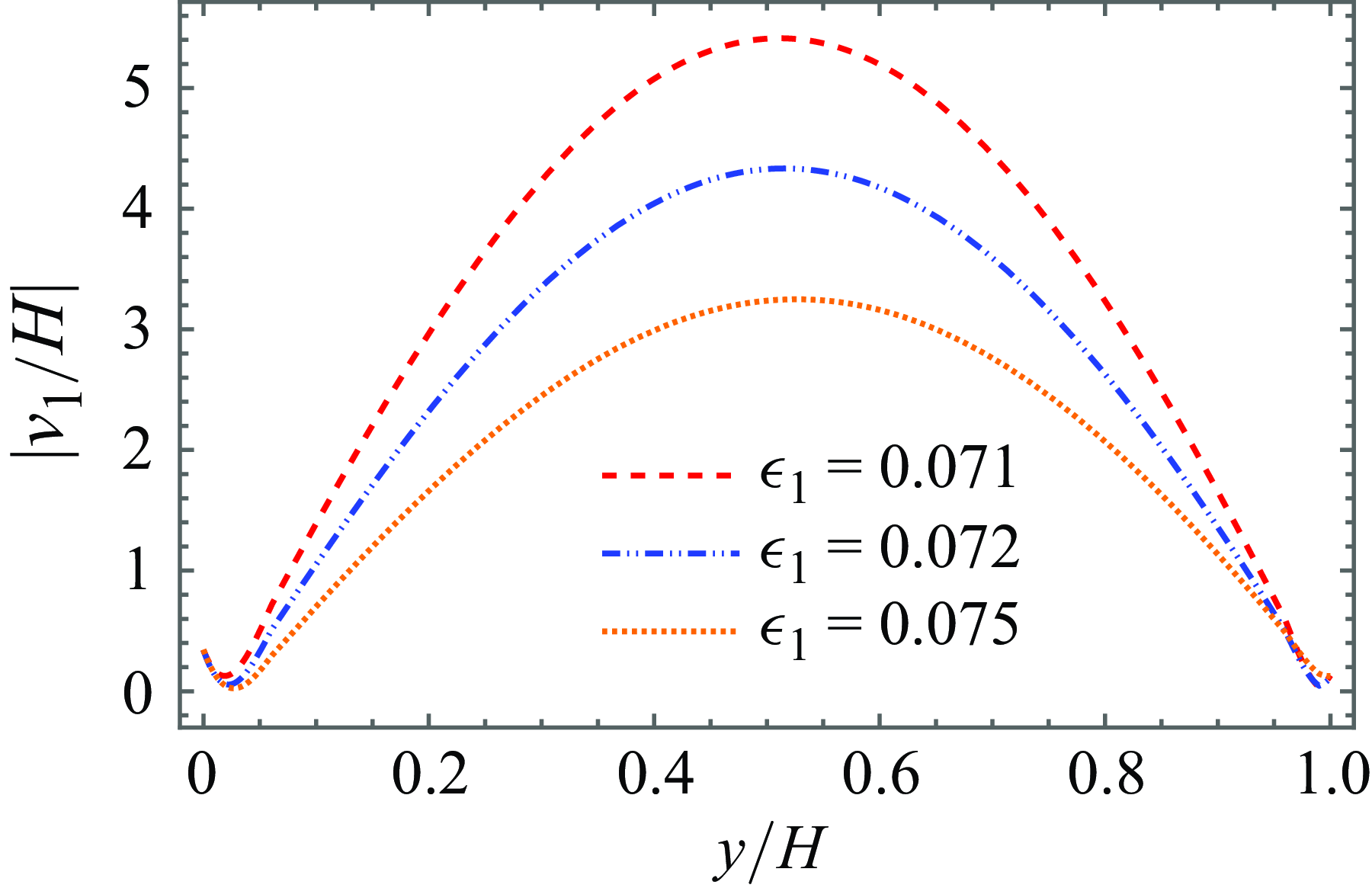
Deflection
 $|\nu _1/H|$
of the plate plotted against
 $y/H$
for different values of
 $\epsilon$
with
 $\theta =\pi /3$
,
 $\Gamma =1+\textrm {i}$
,
 $s=0.65$
,
 $h/H=0.6$
and
 $\delta =0.5$
(a) when one end is fixed and other end is free, and (b) when both ends are fixed.

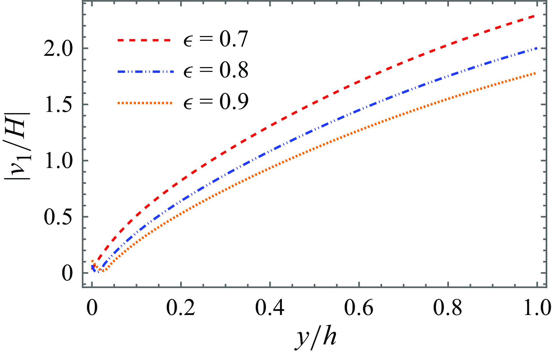
In figure 19(a), the non-dimensional deflection amplitude
 $|\nu _1/H|$
of the elastic porous plate is presented for different values of the flexural rigidity parameter
 $\epsilon$
when the plate is clamped at one end and left free at the other. In contrast, figure 19(b) shows the deflection amplitude for the case where the plate is clamped at both ends. It is observed that the plate deflection increases with a decrease in the plate flexural rigidity. This is due to the reduction in the plate flexural rigidity leads to a reduction in the stiffness of the plate against the wave motion and leads to a higher plate deflection. As shown in figure 19(b), enhanced deflection occurs near the central location of the plate, while negligible deflection is observed at the ends where it is clamped. Similar observations were found for deflection amplitude by an elastic porous plate in a single-layer fluid by Koley et al. (Reference Koley, Kaligatla and Sahoo2015).
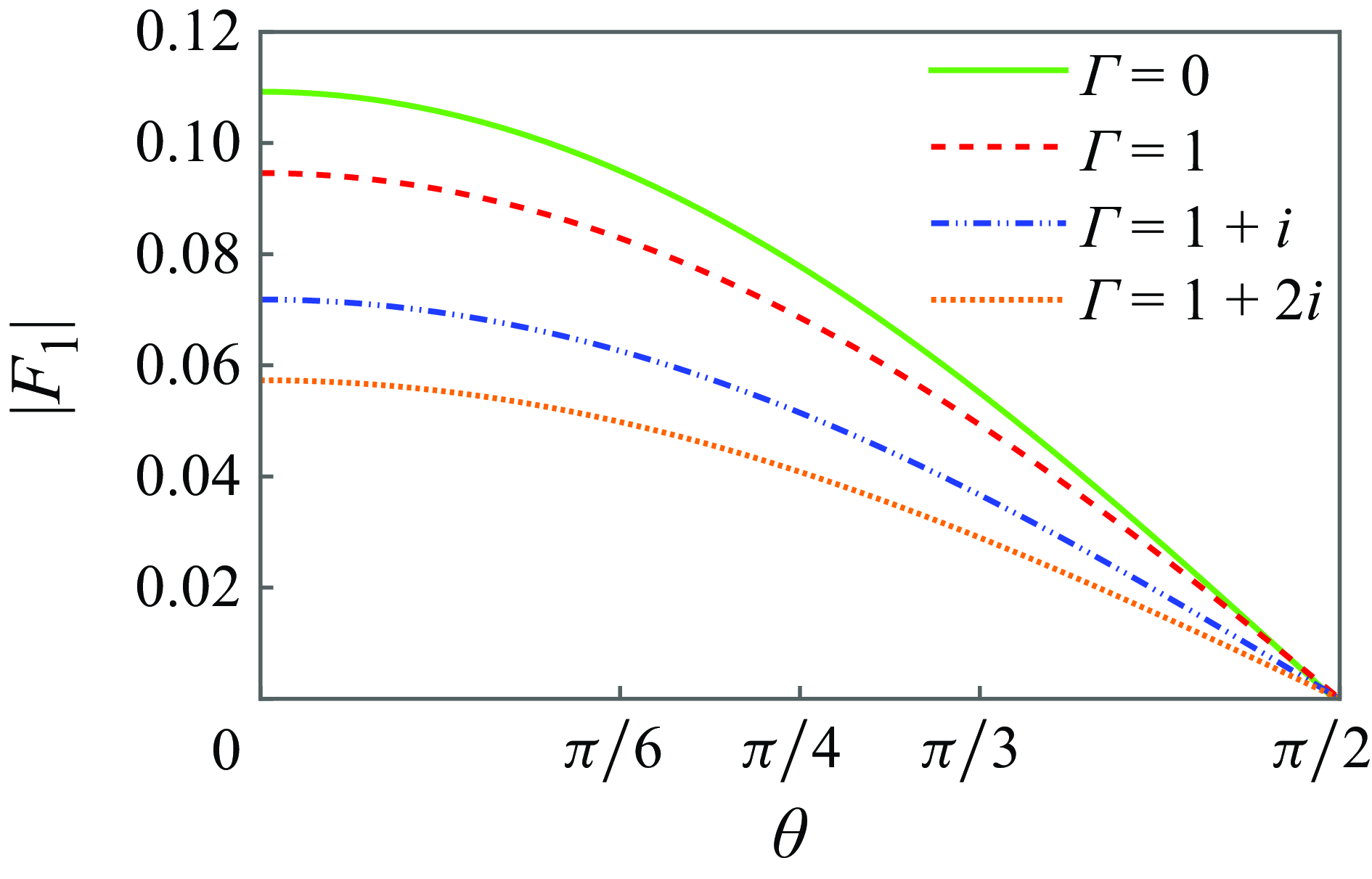
Dynamic force
 $|F_1|$
on the plate plotted against
 $\theta$
for different values of
 $\Gamma$
when
 $s=0.75$
,
 $h/H=0.6$
,
 $\epsilon =1$
and
 $\delta =1$
.

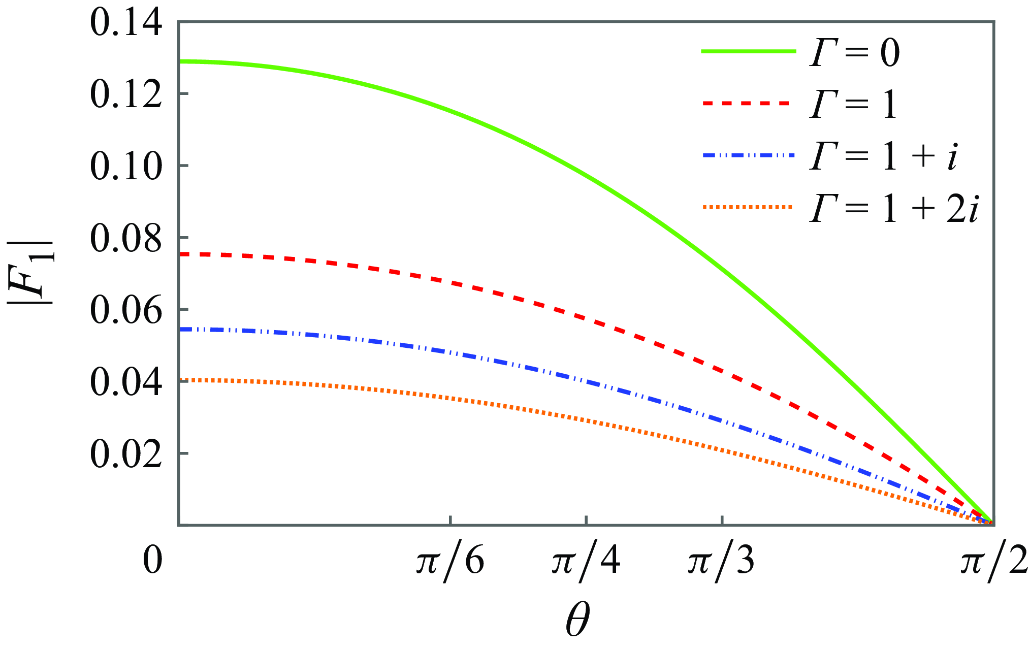
Figure 20 shows the dynamic force
 $|F_1|$
of the plate plotted against the angle of oblique waves
 $\theta$
for different values of the porous-effect parameter
 $\Gamma$
by fixing
 $s=0.75$
,
 $h/H=0.6$
,
 $\epsilon =1$
and
 $\delta =1$
. It is noted that the hydrodynamic force acting on the impermeable elastic plate is significantly higher than the force acting on the permeable elastic plate. The decrease in the wave force on the permeable elastic plate is due to the dissipation of wave energy by the porous structure when a wave passes through the permeable plate. Further, the hydrodynamic force is significant at a smaller oblique angle for all the porous effect parameters. Moreover, there is no hydrodynamic force at an angle closer to
 $90^\circ$
, and this is intuitively expected as waves pass along the plate.
5.1.2. Permeable membrane
Variation of
 $|R_1|$
and
 $|T_1|$
against
 $m_1H$
for different values of
 $\Gamma$
when
 $\theta =\pi /3$
,
 $s=0.75$
,
 $h/H=0.5$
,
 $\epsilon _1=0.1$
and
 $\delta _1=2$
.

Variation of
 $|R_2|$
and
 $|T_2|$
against
 $m_1H$
for different values of
 $\Gamma$
when
 $\theta =\pi /3$
,
 $s=0.75$
,
 $h/H=0.5$
,
 $\epsilon _1=0.1$
and
 $\delta _1=2$
.

Variation of
 $|R_1|$
and
 $|T_1|$
against
 $m_1H$
for different values of
 $\epsilon _1$
when
 $\theta =\pi /3$
,
 $\Gamma =1+\textrm {i}$
,
 $s=0.75$
,
 $h/H=0.5$
and
 $\delta _1=1$
.

Reflected and transmitted wave amplitudes in SM and IM are depicted versus the wavenumber
 $m_1H$
while fixing
 $\theta =\pi /3$
,
 $s=0.75$
,
 $h/H=0.5$
,
 $\epsilon _1=0.1$
and
 $\delta _1=2$
in figures 21 and 22. Figure 21 illustrates that the reflection curves in SM increase monotonically from lower to a specific wavenumber, after which they reach a uniform value for moderate and higher wavenumbers. Figure 22 demonstrates that the reflection curves in IM rise from zero to a specific value before stabilising at a constant level. The opposite trend is noted for transmission curves in SM and IM. Figures 21 and 22 also reveal that the reflection curves in SM and IM decrease as the inertial and resistance effects of the porous parameters increase. A reverse pattern is observed in the case of wave transmission. This observation is intuitively expected, as an increase in porosity not only facilitates higher wave transmission but also reduces the membrane’s resistance to wave motion. Breakwater without porosity exhibits higher wave reflection and lower wave transmission. The present results agree well with those of Suresh Kumar et al. (Reference Suresh Kumar, Manam and Sahoo2007)
Variation of
 $|R_2|$
and
 $|T_2|$
against
 $m_1H$
for different values of
 $\epsilon _1$
when
 $\theta =\pi /3$
,
 $\Gamma =1+\textrm {i}$
,
 $s=0.75$
,
 $h/H=0.5$
and
 $\delta _1=1$
.

In figures 23 and 24, reflection and transmission curves are depicted versus the wavenumber
 $m_1H$
for different values of the membrane tension parameter
 $\epsilon _1$
when
 $\theta =\pi /3$
,
 $\Gamma =1+\textrm {i}$
,
 $s=0.75$
,
 $h/H=0.5$
and
 $\delta _1=1$
are fixed. Figures 23 and 24 demonstrate that the reflection curves increase monotonically for lower wavenumbers, and they attain uniform values for moderate and higher wavenumbers. These plots also illustrate that as the membrane tension parameter increases, the reflected wave amplitude curve increases for fixed smaller wavenumbers. Then, as the wavenumber increases, the reverse pattern is noted. Opposite trends are observed for transmitted wave amplitude curves in SM and IM. It is also significantly noted that a barrier with lower stiffness produces lower wave reflection and higher wave transmission.
Reflected and transmitted wave amplitudes are plotted, in figures 25 and 26, versus the wavenumber
 $m_1H$
for different values of the fluid depth ratio parameter
 $h/H$
in SM and IM when
 $\theta =\pi /3$
,
 $\Gamma =1$
,
 $s=0.75$
,
 $\epsilon _1=0.01$
and
 $\delta _1=2$
are fixed. It is noted that wave reflection is higher when both layers have almost equal depth, i.e.
 $h/H=0.9$
. Also, the wave reflection is lower for the thinner upper layer, i.e.
 $h/H=0.1$
, almost over the entire range of interest. This phenomenon arises due to the resonant interaction between surface and internal waves when the free surface is close to the interface.
Variation of
 $|R_1|$
and
 $|T_1|$
against
 $m_1H$
for different values of
 $h/H$
when
 $\theta =\pi /3$
,
 $\Gamma =1$
,
 $s=0.75$
,
 $\epsilon _1=0.01$
and
 $\delta _1=2$
.

Variation of
 $|R_2|$
and
 $|T_2|$
against
 $m_1H$
for different values of
 $h/H$
when
 $\theta =\pi /3$
,
 $\Gamma =1$
,
 $s=0.75$
,
 $\epsilon _1=0.01$
and
 $\delta _1=2$
.

Variation of
 $|R_1|$
and
 $|T_1|$
against
 $m_1H$
for different values of
 $\theta$
when
 $\Gamma =1+\textrm {i}$
,
 $s=0.75$
,
 $h/H=0.5$
,
 $\epsilon _1=0.01$
and
 $\delta _1=2$
.

Variation of
 $|R_2|$
and
 $|T_2|$
against
 $m_1H$
for different values of
 $\theta$
when
 $\Gamma =1+\textrm {i}$
,
 $s=0.75$
,
 $h/H=0.5$
,
 $\epsilon _1=0.01$
and
 $\delta _1=2$
.

In figures 27 and 28, reflection and transmission coefficients are depicted in SM and IM versus the dimensionless wavenumber
 $m_1 H$
for various values of angle of incidence
 $\theta$
while fixing
 $\Gamma =1+\textrm {i}$
,
 $h/H=0.5$
,
 $s=0.75$
,
 $\epsilon _1=0.01$
and
 $\delta _1=2$
. It is observed that from figures 27 and 28, reflected wave amplitude curves in SM and IM increase for fixed smaller wavenumbers, and thereafter they attain a uniform value for the rest of the wavenumbers. Plots also reveal that reflected wave amplitude curves increase with a decrease in oblique angles. Moreover, it is observed that the reflected wave amplitude curves in SM and IM for
 $\theta =0^{\circ }$
are substantially higher compared with the other amplitude curves. This outcome is intuitively expected as waves hit the permeable membrane without making oblique angles.
Deflection
 $|\nu _1/H|$
of the plate plotted against
 $y/H$
for different values of
 $\epsilon _1$
with
 $\theta =\pi /3$
,
 $\Gamma =1+\textrm {i}$
,
 $s=0.45$
,
 $h/H=0.45$
and
 $\delta _1=1$
when both ends are clamped.

In figure 29, non-dimensional deflection amplitude
 $|\nu _1/H|$
of the permeable membrane is plotted for different values of the membrane tension parameter
 $\epsilon _1$
when the membrane barrier is clamped at both ends and while fixing
 $s=0.45$
,
 $\theta =\pi /3$
,
 $\Gamma =1$
,
 $h/H=0.45$
and
 $\delta _1=1$
. The membrane deflection is found to increase with the decrease in membrane tension. This is attributable to the reduction in membrane tension, which decreases the stiffness of the membrane barrier against wave motion, resulting in greater deflection of the membrane. Enhanced deflection occurs near the central location of the membrane barrier and the membrane deflection is negligible at the ends where it is clamped. Similar results were reported by Suresh Kumar et al. (Reference Suresh Kumar, Manam and Sahoo2007)
5.2. Infinite depth
In this subsection, the reflection and transmission curves in both SM and IM are plotted against the angle of incidence
 $\theta$
for different values of the dimensionless parameter such as the porous effect parameter
 $\Gamma$
, the plate flexural rigidity
 $\epsilon$
and the fluid density ratio
 $s$
. The dimensionless form of the horizontal hydrodynamic force coefficient on the vertical elastic porous plate for infinite depth water is given by
 \begin{eqnarray} F_j=\frac {|B_j|}{\rho _2 g h^2}, \end{eqnarray}
where
 \begin{eqnarray} B_j=\textrm {i} \rho \omega \int _{0}^{\infty } \left ( e^{-Ky}+q(y) + \psi _j (0,y) \right )\,{\rm d}y. \end{eqnarray}
 $|R_1|$
and
 $|T_1|$
plotted against
 $\theta$
for different values of
 $\Gamma$
when
 $s=0.5$
,
 $\epsilon =0.01$
and
 $\delta =2$
.

 $|R_2|$
and
 $|T_2|$
plotted against
 $\theta$
for different values of
 $\Gamma$
when
 $s=0.5$
,
 $\epsilon =0.01$
and
 $\delta =2$
.

 $|R_1|$
and
 $|T_1|$
plotted against
 $\theta$
for different values of
 $\epsilon$
when
 $\Gamma =0$
,
 $s=0.5$
and
 $\delta =2$
.

 $|R_2|$
and
 $|T_2|$
plotted against
 $\theta$
for different values of
 $\epsilon$
when
 $\Gamma =0$
,
 $s=0.5$
and
 $\delta =2$
.

 $|R_2|$
and
 $|T_2|$
plotted against
 $\theta$
for different values of
 $s$
when
 $\Gamma =1+\textrm {i}$
,
 $\epsilon =0.01$
and
 $\delta =2$
.

Reflection and transmission curves are plotted in figures 30–36 for elastic porous plate in infinite depth water against the angle of incidence for different values of non-dimensional parameter. In figures 30 and 31, reflection and transmission curves are plotted in both SM and IM against the angle of incidence for various values of porous effect parameter
 $\Gamma$
when the values of
 $s=0.5$
,
 $\epsilon =0.01$
and
 $\delta =2$
are fixed. It can be seen that the reflection curves in both SM and IM decrease with an increase in the inertial and resistance effect of the permeable elastic plate. It is also noted that the reflection curve is significantly higher for an impermeable elastic plate, while the transmission curve is notably lower. Other observations for reflection and transmission curves in both SM and IM for infinite depth water are qualitatively comparable to those in figures 4 and 5.
Deflection
 $|\nu _1/h|$
of the plate plotted against
 $y/h$
for different values of
 $\epsilon$
when
 $\theta =\pi /3$
,
 $\Gamma =1$
,
 $s=0.5$
and
 $\delta =1$
.

Dynamic force
 $|F_1|$
on the plate plotted against
 $\theta$
for different values of
 $\Gamma$
when
 $s=0.5$
,
 $\epsilon =1$
and
 $\delta =2$
.

In figures 32 and 33, reflection energy and transmission energy curves are depicted in both SM and IM against the angle of oblique wave incidence
 $\theta$
for different values of flexural rigidity parameter
 $\epsilon$
while
 $\Gamma =0$
,
 $s=0.5$
and
 $\delta =2$
are fixed. They reveal that reflection and transmission curves are relatively comparable with those in figures 8 and 9 for the case of the complete elastic porous plate for finite depth water. It is also significant that enhanced reflection in IM is almost complete for
 $\epsilon =0.5$
.
Energy reflection and transmission curves are plotted in IM against the angle of incidence for various values of
 $s$
when
 $\Gamma =1+\textrm {i}$
,
 $\epsilon =0.01$
and
 $\delta =2$
are fixed in figure 34. The reflection curve is notable when the density of the two fluids are close to each other. Similar observations can be made as compared with those in figure 13.
Figure 35 shows the non-dimensional deflection of the elastic porous plate plotted for different values of the non-dimensional flexural rigidity when the plate is clamped at both ends, and
 $\theta =\pi /3$
,
 $\Gamma =1$
,
 $s=0.5$
and
 $\delta =1$
are fixed. Again, the deflection of the permeable elastic plate for infinite depth water is similar to those in figure 19(a).
Figure 36 shows the hydrodynamic force acting on the elastic porous plate for infinite depth water plotted against the angle of wave incidence
 $\theta$
for different values of porous effect parameter
 $\Gamma$
by fixing
 $s=0.5$
,
 $\epsilon =1$
and
 $\delta =2$
. The dynamic force acting on the elastic porous plate is qualitatively comparable to those depicted in figure 20 for finite depth water.
Similar observations can be made in the case of permeable membrane as compared with the elastic porous plates in two-layer fluids having infinite depth water.
6. Conclusions
The purpose of this paper was to derive explicit analytical solutions for the oblique wave scattering problem involving either an elastic porous plate or a permeable membrane in both the cases of finite and infinite depths of water in a two-layer fluid. The original physical problem in the half-plane is modelled as a mixed boundary value problem for the modified Helmholtz equation with higher-order structural boundary conditions. The solution procedure mainly involves:
-
(i) the transformation from originally defined physical problems in the half-plane into a couple of quarter-plane problems for flexible porous wave potentials;
-
(ii) an establishment of two novel integro-differential relations to connect the flexible porous wave potentials with auxiliary wave potentials; and
-
(iii) use of generalised orthogonal relation to derive explicit analytical solutions for auxiliary wave potentials.
After that, the solution potentials are derived explicitly in terms of the analytically obtained auxiliary wave potentials by using the integro-differential relation. Explicit analytical expressions are derived for the reflection and transmission coefficients corresponding to the SM and IM, respectively. Also, the deflection of the flexible porous structures is obtained analytically.
In both the SM and IM, the energy reflection and transmission are presented visually for various values of the non-dimensional parameters versus the wavenumber and angle of incidence. Higher resistance and inertial porous effects in either an elastic porous plate or a permeable membrane can lead to the production of lower reflection waves. A plate exhibiting greater flexural rigidity is found to generate waves with lower reflection. Plates with these optimal characteristics play a crucial role in coastal defence by effectively reducing wave forces. For a elastic porous plate, energy reflection curves exhibit a resonant minimum within a certain range of wavenumbers, while the energy transmission curves reach a resonant maximum within the same range. Also, zero wave reflection and full wave transmission are found at certain smaller wave frequencies for an elastic porous plate. A membrane exhibiting lower stiffness is found to generate waves with lower wave reflection and higher wave transmission. Higher wave reflection is observed when both layers have equal depth, while lower wave reflection occurs with a thinner upper layer. Notably, reflection curves are significantly lower when waves interact with the structures with forming oblique angles. Moreover, a structure with lower stiffness deforms or bends more under the action of a wave load, resulting in higher structure’s deflection. This work significantly enhances the design and development of breakwaters by adjusting the porous and flexible nature of the structure appropriately to achieve the desired reflection, thereby mitigating the harmful effects of oblique waves. It is noteworthy that the results obtained for the hydrodynamic scattering quantities are validated by those of Manam & Sahoo (Reference Manam and Sahoo2005) and Suresh Kumar et al. (Reference Suresh Kumar, Manam and Sahoo2007) for a porous plate and a permeable membrane in a two-layer fluid, respectively.
In this paper, symmetric flexible porous structures are considered in a two-layer fluid system. The proposed methodology decomposes the original half-plane problems into a couple of quarter-plane problems, taking advantage of the symmetric nature of the structures. The present analytical approach may not be suitable for the problems in a two-layer fluid with non-symmetric structures. Further extension of the solution procedure can be possible for a mixed boundary value problem associated with the scattering of water waves by partially immersed or submerged flexible porous barriers in a two-layer fluid. The present analytical method can be adapted to oblique wave scattering problems involving multiple flexible porous barriers in a two-layer fluid.
Acknowledgements.
We would like to thank the Editor and the Reviewers for their valuable comments and suggestions which improved the presentation of the paper.
Declaration of interests.
The authors report no conflict of interest.