I. INTRODUCTION
In modern societies, identification and authentication of items and persons are more and more required particularly in the context of the Knowledge Society and the Internet of Things paradigm. Among the useful techniques for identification, wireless technologies are the most relevant and enabling methods. Radio frequency identification (RFID) is an automated wireless data-capturing technique, which utilizes radio frequency (RF) waves for data transmission between the transponder and the reader [Reference Dobkin1]. RFID traditionally uses an IC chip inside the transponder to store the useful information regarding the item or the person to be identified or tracked. RFID reader could be used to retrieve this information, which is later relayed to a database or a big data system for processing and exploitation [2]. RFID offers lot of advantages as large reading range, no constraint of sight's line, complete automation, and large amount of information storage capacity.
Despite all these advantages, cost of RFID tag still remains a huge feature, which has curtailed its influx into the market (http://www.idtechex.com/). This made it imperative to develop an alternate low-cost way of object identification. As a result, over the years, a lot of research efforts have been devoted toward developing chipless RFID technology [Reference Tedjini and Karmakar3]. Besides reducing the cost of tag, chipless RFID is seen as the master technology to enable smart applications such as the Internet of Things. Chipless RFID tags are passive elements and have compact size. They can be easily attached to items for purpose of identification and potentially for sensing [Reference Manzari and Marrocco4]. For other advanced applications, tags can be attached to persons and animals, sometimes implanted within body for medical monitoring [Reference Marroncelli, Trinchero, Lakafosis and Tentzeris5, Reference Singh, Vena, Perret and Tedjini6].
One attractive alternative is to consider the printed information on the item or its packaging as an identifier. This supposes that the marked information (letters, numbers, specific signs, etc.) have specific and unique characteristics that allow their identification. Only few attempts have been found in the literature for the exploitation of alphabets as RF identifiers. Keskilammi and Kivikoski have demonstrated RFID tag antenna using text as a meander line [Reference Keskilammi and Kivikoski7]. The same principle can be adapted to any text if some specific, but non-standard, shapes and sizes are determined thanks to electromagnetic (EM) simulation that take into account the RFID chip impedance. Marroncelli et al. [Reference Amin, Bhuiyan, Karmakar and Winther-Jensen8], demonstrated the use of some specific texts as low-cost paper-printed antennas for Wireless Identification and Sensing Platform WISP-based RFIDs. As far as real alphabet using standard fonts are considered, the most useful contributions are in [Reference Rubayet-E-Azim and Karmakar9, Reference Vena, Singh, Tedjini and Perret10] where metallic Latin alphabets are used as single identifiers and an identification technique based on radar approach is developed.
In this paper, we consider the signs of another alphabet, namely the Arabic alphabet. Even if the Arabic alphabet is also based on single signs just as Latin alphabet, the shape are very different. Moreover, in Arabic alphabet the use of punctuation as points is very critical as some letter differs only by points. So, we are aimed to demonstrate that different letters exhibit different EM signatures i.e. the characteristics of the signal in frequency domain would be different and this could be recorded in advance and used to identify the correct letter. In more advanced design, each letter can be considered as an ‘RF Elementary Coding Particle’ providing a unique response and the association of independent particles could be used to obtain more complex and rich EM signature. Of course the EM coupling between individual letters must be taken into account in this case. One main application of frequency-domain-based chipless RFID tags is security where the EM signature technique is used to protect confidential data in RFID systems from unauthorized readers.
Thus, this paper is structured as follows. In Section II, simulation's method will be discussed. In Section III, the case of Latin alphabet will be studied, while Section IV will focus on Arabic alphabet. In Section V a strategy for classification and identification is carried out together with lookup tables. Lastly, conclusion and scope for future work is presented.
II. SIMULATION METHOD
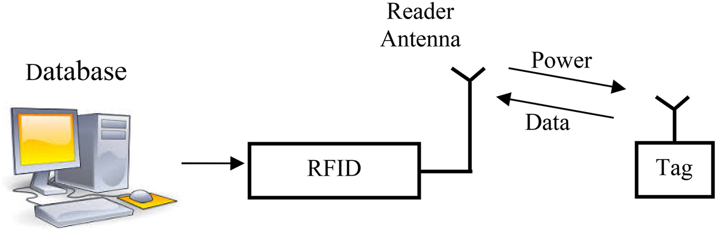
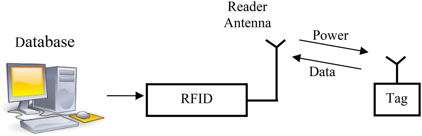
The block diagram of a typical RFID system is shown in Fig. 1. Due to the absence of any silicon IC, the chipless tag is completely passive, low cost, robust, and does not require a power supply. Various coding techniques are used for chipless tags. They are based on time-domain [Reference Ramos, Girbau, Lazaro and Rima11], frequency-domain [Reference Preradovic, Balbin, Karmakar and Swiegers12], phase [Reference Balbin and Karmakar13], and imaging [Reference Das14]. Among these techniques, the frequency-domain provides the best data capacity for RFID tags [Reference Preradovic and Karmakar15, Reference Islam and Karmakar16].
A block diagram of a typical RFID system.
A) Principle of the frequency signature
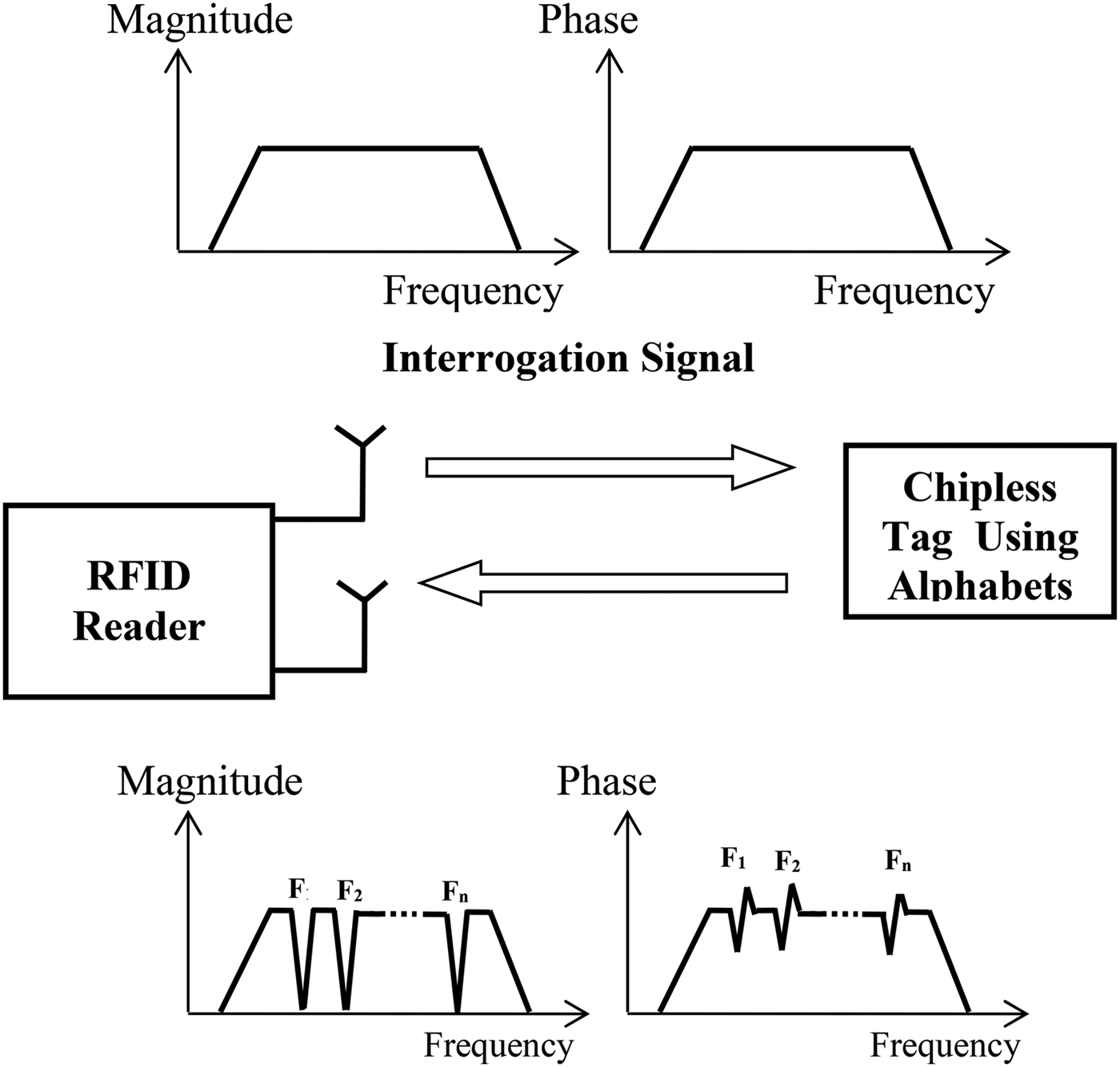
The concept of frequency signature is based on the interrogation of the RFID tag with a multi-frequency signal and distinction of attenuated frequencies (represent by logic ‘0’) from non-attenuated frequencies (represent by logic ‘1’) [Reference Preradovic, Roy and Karmakar17–Reference Tedjini, Perret, Vena and Kaddour19]. The variation of the amplitude and/or phase of the signal sent back to the reader determines the nature of the logic state ‘0’ or ‘1’. As an example, by encoding N-bit digital word with N-attenuated frequencies, where each bit represents a single frequency, we can create a unique frequency signature associated with the tag. Moreover, using any metallic symbol will provide a specific EM signature that can be described by its resonance and anti-resonance frequencies.
Figure 2 shows the proposed operating principle of the frequency signature-based chipless RFID tag. The frequency signature then represents the total response of the characterized chipless by a set of resonant and anti-resonant frequencies. For the purpose of application, each tag should have a unique code (tag ID) depending straightforwardly on the shape of the tag. The proposed chipless tag based on the alphabet geometry, may be then an adequate solution for the security of confidential data in RFID systems due to its complex and unique EM signature.
Principle of the EM signature for chipless RFID tags.

B) Simulation procedure
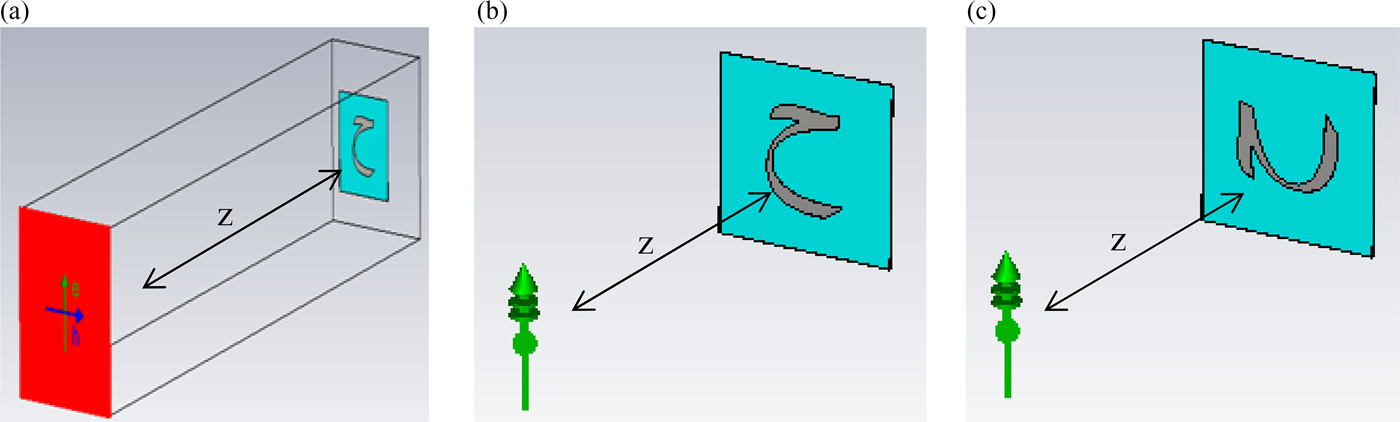
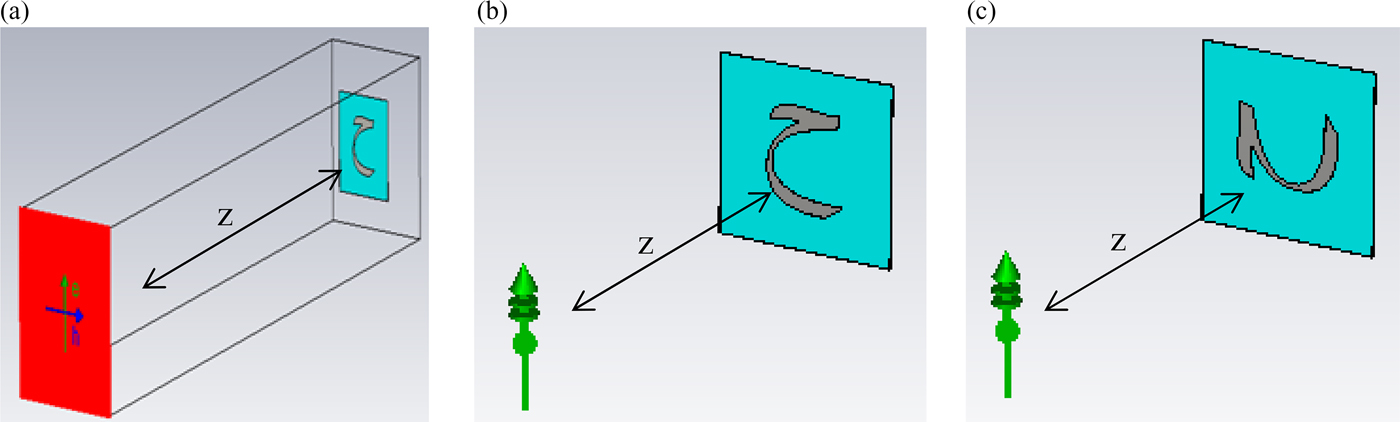
The metallic Arabic letters was simulated using the software CST Microwave Studio. We have first illuminated each letter with an incident plane wave and a probes are placed around (0 along the x-direction, 0 along the Y-axis, and 350 mm along the Z-axis) it in order to determine both the electric field and the radar cross-section in the far-field region over a wide frequency band extending from 1 to 10 GHz. Open boundary conditions are used throughout this paper. The magnitude of the incident electric field is 4 V/m. Therefore, the complete simulated EM response of the letter was analyzed (Fig. 3).
Analysis of the frequency spectrum reveals the presence of resonance peaks mainly depending on the length of induced surface current paths within the shape of the letter. As the Arabic letters are rich in forms and characterized by different shapes, their electrical length may be different which leads to different resonant frequencies. As we will see in the next sections, the localization of these resonances in the EM spectrum permits us to identify all letters of the Arabic alphabet without ambiguity. Therefore each letter can be seen as a coding particle and the association of several letters can be considered for more advanced and complex coding.
III. LATIN ALPHABET CASE
A few years ago, Keskilammi and Kivikoski have shown that some metallic words can be used as radiating elements for transponder, in top of their visual identification [Reference Keskilammi and Kivikoski7]. Since then, few research efforts have been devoted toward developing chipless RFID tags based on letters, numbers, specific signs, etc. [Reference Rubayet-E-Azim and Karmakar9, Reference Vena, Singh, Tedjini and Perret10].
In an ulterior work [Reference Rubayet-E-Azim and Karmakar9], the authors have developed for the first time chipless RFID tags based on Latin letters, in order to combine classical visual identification with EM identification. They have demonstrated by simulation and measurement that metallic letters can be identified by use of EM wave as interrogation signal. Both simulated and measurement results have shown that it is possible to recognize the entire Latin alphabet composed of 26 letters with high confidence.
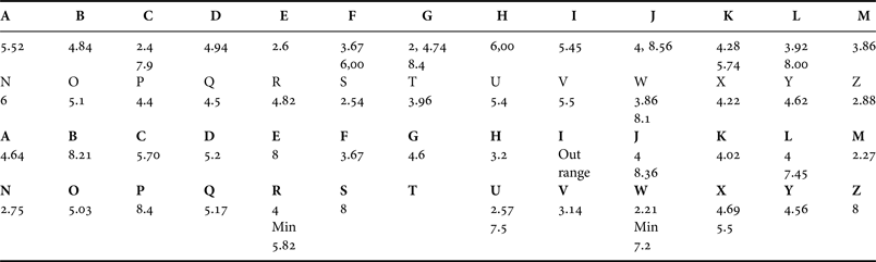
Arial alphabet was considered with vertical letters with 24 mm of width and 24 mm of height. It is shown that each letter is characterized by its own and unique EM signature. It is also shown that varying the letters size may produce only a frequency shift of resonances. Table 1 provides the lookup table for 24 mm Arial font as discussed in [Reference Rubayet-E-Azim and Karmakar9, Reference Vena, Singh, Tedjini and Perret10] (Fig. 4).
Principle of the analysis technique (z = 350 mm): (a) incident plane, (b) vertical polarization, (c) horizontal polarization.
Layout of the 28 letters designed with Arial font.

Lookup table for 24 mm Arial font. Up: vertical polarization. Below: horizontal polarization. Resonant frequencies are in GHz. ‘Min’ indicates anti-resonance frequency. The used substrate is Kapton (permittivity: ɛ r = 3.5, loss: tanδ = 0.004, thickness: t = 0.1 mm).

IV. ARABIC ALPHABET CASE
A) Design of Arabic letters tags with Arial font
Arabic alphabet may be written with many fonts; therefore in our study we have considered the Arial font due to its simplicity and widespread use. First, the letters were drawn with the software AUTOCAD 2014 with the help of the text option ‘explode’. Figure 2 shows the layout of Arabic letter with Arial font. Then, the different shapes of all letters were exported to the EM simulator CST for analysis.
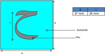
A font height of 24 mm was chosen as standard in order to obtain resonating structure in the ultra-wideband range 1–10 GHz. Figure 5 shows an example of a tag structure based on the Arabic letter  with main design parameters.
Tag layout with different design parameters; a = 37 mm; c = 24 mm; substrate flexible Kapton (relative permittivity: ɛ r = 3.5, loss tangent: tanδ = 0.004, thickness: t = 0.1 mm).

Alphabet letters were placed in the ‘xoy’ plane, and an incident plane wave traveling along the ‘z’ direction with horizontal (along the x-axis) or vertical polarization (along the y-axis) was considered to excite the letter-tag. Both X and Y components of the far-field were recorded but Y component (component along transmitting antenna's polarization) is of more interest for us since we are interested in using mono-static configuration.
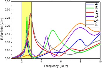
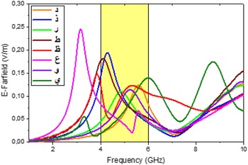
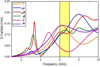
Simulations were done for all the 28 Arab letters with both horizontal and vertical polarizations. Selected letters showing resonances in the first (2–3 GHz), medium (4–6 GHz), and last ranges (6–10 GHz) of the explored band 1–10 GHz, are discussed below. Moreover, letters showing multi-resonances and letters characterized with one to three points in their geometries were presented.
B) Results for horizontal polarization
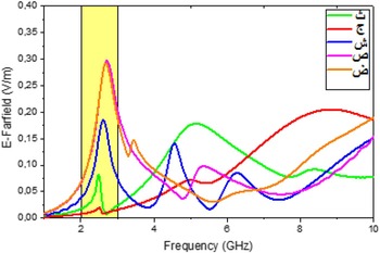
1) Letters showing peaks in 2–3 GHz
This set of letters is characterized by the largest length in the horizontal direction. The letter  has the lowest resonant frequency due to its length. It is also interesting to notice that the letters
 ,
 have nearly the same response. This behavior is quite understandable as the only difference between the two letters is the point of punctuation. In order to allow the distinction between these we will suggest a slight modification of the punctuation here after (Fig. 6).
E-far-field versus frequency for Alphabets  , and


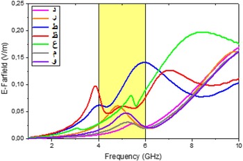
2) Letters showing peaks in 4–6 GHz
These letters have a medium length in the horizontal direction. As expected the letters  ,
 have nearly the same response (Fig. 7).
E-far-field versus frequency for Alphabets  , and


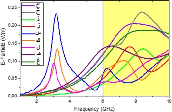
3) Letters showing peaks in 6–10 GHz
These letters have a minimum length in the horizontal direction. As expected the letters  , on one side and
 ,
 on a second side have nearly the same responses (Fig. 8).
E-far-field versus frequency for Alphabets  , and


C) Vertical polarization
1) Letters showing peaks in 2–3 GHz
In the vertical direction, the letter  has the largest length and therefore it exhibits the lowest resonance frequency.
2) Letters showing peaks in 4–6 GHz
As expected the letters, , have nearly the same responses. Moreover, the letters  ,
 have the largest resonance frequency and nearly same responses.
3) Letters showing peaks in 6–7 GHz
It is interesting to notice that the letter has several vertical resonances due to the existence of several specific parts in the vertical direction (Figs 9–11).
E-far-field versus frequency for Alphabets  and


E-far-field versus frequency for Alphabets  and


E-far-field versus frequency for Alphabets  , and


D) Letters with multi-resonances
As it can be noticed from the previous sections, some of the alphabets have several resonance frequencies in horizontal and/or vertical polarizations. As it can be observed from the shape of the letters, the potential of resonance in the vertical polarization is more effective. Indeed some letters have several specific lengths in that orientation. Tables 2 and 3 provide some resonances for the two polarizations.
Multi-frequency resonances of some letters obtained with horizontal polarization.
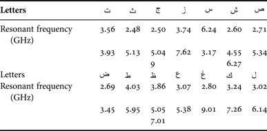
Multi-frequency resonances of some letters obtained with vertical polarization.

E) Letters with points
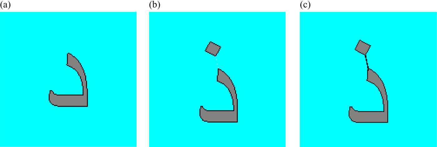
As noticed in the Introduction, the Arabic letters can differ only by adding one, two or three points. This could be a source of ambiguity when comparing the EM signature of two letters having only points as difference. Single point, due to its size, cannot introduce of modify the EM response in the considered frequency band. A compromise is used to overcome this problem is to connect the punctuation points to the body of the letter as it is illustrated in Fig. 12. The connection is made by very thin straight line in order to avoid any visual modification of the footprint of the letter. In our simulation, we used a substrate of 0.1 mm of thickness. Two examples for the case of one point and three points are discussed below:
Example of a letter with one point: (a) letter ‘’. (b) letter ‘’. (c) letter ‘’ with connection.

1) Example of letter with one point: letter ‘ ’
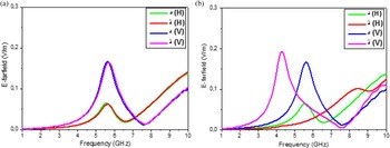
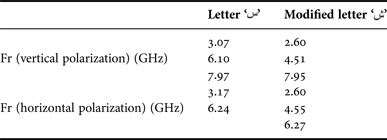
To demonstrate the effect of this slight modification we simulated the original ‘ ’ letter and the modified one obtained by the connection of point to the body of the letter. Simulation results are shown in Fig. 13. The modification is clearly visible in the figure and the new resonances of the modified letter ‘’ are given in Table 4.
E-far-field versus frequency for Alphabets ‘’ and ‘’ (a) before (b) after connection.

Resonance frequencies of letter ‘ name="S2052841815000160_inline12"/>’ and ‘’ obtained with both horizontal and vertical polarizations.

2) Example of letter with three points: letter ‘’
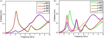
The same study has been conducted for the letter ‘ name="S2052841815000160_inline34"/>’. In that case we are dealing with a group of three points. We just added a very thin straight line of 0.1 mm of thickness. This straight line connects the three points together and to the body of the letter. This modification is shown in Fig. 14. We simulated the original letter ‘ ’ and the modified one and we have found that the modification is also visible in the figure and the new resonances of the modified letter ‘’ are given in Table 5. Simulation results are shown in Fig. 15.
Example of a letter with three points: (a) letter ‘’, (b) letter ‘ ’, (c) letter ‘’ with connection.

E-far-field results in dual polarization for letters ‘’ and ‘’: (a) before, (b) after connection.

Resonance frequencies of letter ‘’ and ‘’ obtained with both horizontal and vertical polarizations.

V. STRATEGY OF IDENTIFICATION
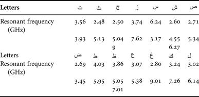
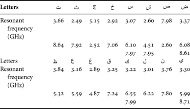
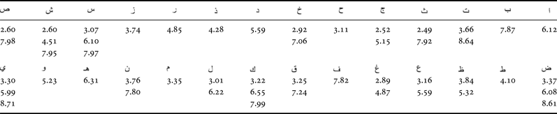
With the aim is primarily to harness these results and propose a chipless identification technique based on the use of Arabic alphabet, it is required to define a set of letters having different EM signature and providing different resonances. Compiling the results discussed in the previous section, it is quite straightforward to define a lookup table for identification purpose. Mapping the resonances to the letters the complementary following tables can be constructed.
From these tables one can identify and recognize the letters simply by measuring the resonant frequencies but for both polarizations. In practice, it is possible to excite the two polarizations in the same time, but the vertical and horizontal fields should be measured separately.
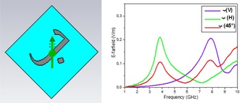
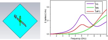
Moreover, the orientation of the excitation and reading antennas are important parameters. To study such effects, we simulate of all the alphabets with an angle of 45°. In this situation, both horizontal and vertical field components are generated. In the figures mentioned we reported the results for two letters. In each case we compare the frequencies obtained for the three orientations of the excitations: horizontal, vertical, and 45°. We clearly notice that for 45° we have all the frequencies for horizontal and vertical cases. Hence, a robust system could be composed of three antennas: one for the excitation at 45° and two for reading, one horizontal, and one vertical (Figs 16 and 17). Moreover, some specific signs (such as cross) can be added in order to calibrate the orientation of the reader separately (Table 6 and 7).
Simulation results for the letter ‘ ’: left is the orientation of the excitation antenna at 45°, and right the simulation results for the three orientations. All resonant frequencies are exhibited when the excitation is at 45°.

Simulation results for the letter ‘ ’: left is the orientation of the excitation antenna at 45° and right the simulation results for the three orientations. All resonant frequencies are exhibited when the excitation is at 45°.

EM response lookup table for 24 mm-height alphabet using horizontal polarization.

EM response lookup table for 24 mm-height alphabet using vertical polarization.

VI. CONCLUSION
In this paper, the EM signature of Arabic alphabets was investigated numerically in order to use them as RF elementary coding particles for chipless RFID applications. The standardized 28 Arial font Letters of 24 mm of height was studied for that purpose. For the simulation each letter was considered on thin and flexible Kapton substrate of size 37 × 37 mm2, permittivity 3.5, loss tangent 0.004, and thickness 0.1 mm. The EM signatures for both field polarizations were simulated in the frequency band 1–10 GHz. Our results unambiguously show that using both vertical and horizontal responses allow the identification of letters. One major characteristic of Arabic letter is the punctuation signs, as many letters can differ only by points. To overcome this ambiguity, letters with punctuation (one to three points) were modified slightly by connecting the points with a straight and very thin strip to their main bodies in order to differentiate their EM responses from similar letters without points. All these results allow one to finally build a lookup table for identification of the 28 letters. An example of this identification tables is provided in this work.
Moreover, we observed that bandwidths of the resonances of Arabic letters are quite wide. This is one of the most salient differences when compared with Latin alphabet. We think that coding capacity is not the real issue for this kind of letters. The most important is to be able to recognize all the alphabets without ambiguity. This work demonstrates this potential on the basis of the measurement of the resonant frequencies. But other approaches for the global identification of the Arabic alphabet based on the exploitation of the full EM signature can be considered and should lead to more powerful and secured identification technique. Future work will focus on that topic.
Acknowledgements
This article was funded by the Deanship of Scientific Research (DSR), King Abdulaziz University, Jeddah. The authors, therefore, acknowledge with thanks DSR technical and financial support. The authors would like to thank the team of LCIS laboratory for the fruitful discussions on that topic.
 Oussama Boularess received the Master degree in Electrical and Electronics from the University of Tunis El Manar, Faculty of Sciences, in 2013. He is currently working toward the Ph.D. degree in System Communication at the National Engineering School of Tunis (ENIT), University of Tunis El Manar. His areas of interests include chipless RFID design, ultra-wideband (UWB) antenna designs, UWB transceiver design for chipless RFID applications, and Passive RFID.
 Hatem Rmili was born in Sakiet Sidi Youssef, Tunisia. He received the B.S. degree in general physics from the Science Faculty of Monastir, Tunisia in 1995, and the DEA diploma from the Science Faculty of Tunis, Tunisia, in quantum mechanics, in 1999. He received the Ph.D. degree in Physics (electronics) both from the University of Tunis, Tunisia, and the University of Bordeaux 1, France, in 2004. From December 2004 to March, 2005, he was a research assistant in the PIOM laboratory at the University of Bordeaux 1. During March 2005 to March 2007, he was a Postdoctoral Fellow at the Rennes Institute of Electronics and Telecommunications, France. From March to September 2007, he was a Postdoctoral Fellow at the ESEO engineering school, Angers, France. From September 2007 to August 2012, he was an associate professor with the Mahdia Institute of Applied Science and Technology, Department of Electronics and Telecommunications, Tunisia. Actually, he is an Associate Professor with the Electrical and Computer Engineering Department, Faculty of Engineering, King Abdulaziz University, Jeddah, Saudi Arabia. His main research activities concern antennas, metamaterials, and metasurfaces.
 Taoufik Aguili received his Engineering degree in Electrical Engineering and his Ph.D. degree in Telecommunications from INSA, France. He is working as a Professor at the National Engineering School of Tunis (ENIT). His research activities include electromagnetic microwave circuits modeling and analysis of scattering and propagation phenomena in free space.
 Smail Tedjini is a Doctor in Physics from Grenoble University in 1985, an Assistant Professor of Grenoble Institute of Technology (Grenoble-INP) from 1981 to 1986, and a Senior Researcher for the CNRS (Research French National Center) from 1986 to 1993. He became a University Full Professor in 1993 and since 1996 he has been a Professor at the Esisar, Embedded Systems, Department of Grenoble-INP. His main teaching topics concern Applied Electromagnetism, Radio Frequency, Wireless Systems, and Optoelectronics. Now he has more than 30 years’ experience in academic education, research, and management of university affairs. He is the founder and past Director of the LCIS Laboratory. He is the founder of ORSYS group and he leaded this group from 2008 to 2014. He supervised more than 35 Ph.D. and he has more than 250 publications. He serves as Examiner/reviewer for ten Ph.D. degrees for universities in many countries (France, Germany, Finland, Spain, Ireland, Italy, Sweden, Vietnam, Australia, Singapore, India, Brazil, Egypt, Maghreb, etc.). He is the member of several TPC and serves as expert/reviewer for national and international scientific committees and conferences including journals such as Piers, IEEE (MTT, AP, Sensors, and MGWL), URSI, ISO, ANR, OSEO, and FNQRT. He is a Senior Member of IEEE, President and founder of the IEEE-CPMT French Chapter, Vice-President of IEEE Section France, and elected as the Vice-Chair of URSI Commission D ‘Electronics & Photonics’ in 2008. He was reelected as Vice-Chair of IEEE-France-section and he is serving as the Chair of URSI Commission ‘D’ for the triennium 2011–2014, in particular the preparation on the General Assembly and Scientific Symposium which was held in Beijing, August 2014.