1. Introduction
Piping systems have been extensively implemented as an efficient material transportation method across various industrial sectors, including general manufacturing, nuclear facilities, oil and gas operations, and military equipment [Reference Zhao, Kamezaki, Yamaguchi, Konno, Onuki and Sugano1–Reference Zhou, Ni, Dai and Wang3]. Certain pipelines traverse complex geographical terrains and are prone to surface degradation phenomena such as cracks and leakage points due to prolonged exposure to corrosion, mechanical stresses, and environmental factors [Reference Huang, Honglong and Mingfei4], significantly compromising transportation efficiency. Consequently, regular inspection and maintenance of pipelines are imperative.
Conventional inspection methodologies, such as scheduled manual inspections, random sampling techniques, and premature decommissioning protocols, often exhibit limitations in operational efficiency, labor intensity, and cost-effectiveness [Reference Min, Yang and Wang5]. In contrast, robotic inspection systems equipped with multi-sensor configurations have emerged as a superior solution [Reference Cao, Tang and Wang6], offering enhanced operational efficiency and systematic detection capabilities. This advanced approach represents an inevitable trend in modern pipeline integrity management.
Significant research has been devoted to the structural design of pipeline inspection robots, with considerable progress achieved. Current literature primarily focuses on internal pipeline inspection robots. For instance, Liu et al. [Reference Liu, Song, Fang, Zhao and Cao7] designed a soft-bodied robot capable of stable locomotion in pipelines with varying diameters, non-uniform cross-sectional shapes, humid or oil-coated inner surfaces, and underwater environments. Wang et al. [Reference Wang, Wang, Zhou, Feng and Wang8] developed a pipeline inspection robot employing a helical drive mechanism, which demonstrated stable operation within pipelines of 332–438 mm in diameter. However, internal inspection robots prove inadequate for pipelines conveying specialized materials or exhibiting complex internal geometries, necessitating external inspection solutions. Xu et al. [Reference Xu, Wang, Du, Bao, Hu and Yuan9] designed a wheel-clamping robot with magnetic hemispherical wheels, adaptable to pipelines of varying curvatures, and capable of both internal and external locomotion. Dutta et al. [Reference Dutta, Reddy and Dwivedy10] designed a robot that grips pipes using a bistable flexible mechanism. Lee et al. [Reference Lee11] proposed a C-shaped wheel-clamping robot achieving inspection speeds exceeding 30 mm/s on external pipeline surfaces. Similarly, Li et al. [Reference Li, Huang and Fang12] implemented a three-wheeled robot featuring wheels positioned at 0°, 90°, and 180°, enabling circumferential clamping and multi-sensor-based defect detection.
Bio-inspired designs have further advanced this field: Karkoub et al. [Reference Karkoub, Bouhali and Sheharyar13] created an inchworm-mimetic robot utilizing electromagnetic foot mechanisms for metallic pipeline adhesion. Li et al. [Reference Li, Huang, Tu, Tian and Wang14] developed a spherical tank inspection robot incorporating elastic damping suspension and composite wheels, with an adjustable frame and rotational joints to accommodate curved pipelines of diverse diameters. Addressing petroleum pipeline maintenance, Duanmu et al. [Reference Duanmu, Chen and Zheng15] engineered a collision-resistant wheel-clamping robot with real-time posture correction capabilities. Liu et al. [Reference Liu, Li and Zhong16] proposed a dual-articulated robot model capable of rapid pipeline transition during obstacle avoidance. Urdaneta et al. [Reference Urdaneta, Garcia, Saltaren, Contreras and Ejarque17] introduced a tensegrity-based external inspection robot exhibiting lightweight construction, diameter adaptability, and high-speed mobility. Han et al. [Reference Han, Ahn and Moon18] designed a two-drive-module robot with enhanced obstacle negotiation and rapid locomotion on large pipelines. Gharib et al. [Reference Gharib, Alnouri, Alsulaiti, Buhendi and Al-Hamidi19] developed a modular vertical pipeline climber employing drone-like propulsion for flexible movement. Abdellatif et al. [Reference Abdellatif, Alrasheed, Felemban, Brahim, Jifri, Abdelkader and Shamma20] innovated a hybrid drone-climber system for accessing elevated pipelines in complex environments.
This paper presents a novel external pipeline robot featuring a composite drive mechanism and bilateral clamping assemblies. Unlike conventional modular robots that rely on increasing the number of drive modules to cross obstacles [Reference Han, Ahn and Moon18] or C-shaped robots with fixed dimensions [Reference Lee11], this design introduces a novel dual-slider multi-link mechanism. The core innovation of this mechanism lies in its kinematic decoupling capability: it utilizes the coordinated linear motion of dual sliders to significantly amplify the opening range of the clamping arms without compromising structural rigidity. This allows the robot to rapidly switch between axial forward movement and circumferential rotation modes using a single drive source, solving the conflict between "large-range diameter adaptability" and "compact structural volume" found in existing designs. First, the structural composition and working principle of a wheel-clamping external pipeline robot with obstacle avoidance and diameter adjustment functions are introduced. To analyze the range of pipe diameters the robot can accommodate, a mathematical model of the spatial relationships between the robot’s components was established and subjected to mathematical analysis to determine the range of pipe diameters the gripping mechanism can accommodate. A force analysis was also conducted to determine the minimum driving torque required for axial movement and circumferential rotation, establishing a mechanical analysis model for the robot. An experimental environment was set up to conduct experimental research on the developed robot prototype.
2. Structural design of the robot
Considering that external pipeline inspection robots need to traverse complex pipeline environments or overcome obstacles such as T-shaped intersections and valves during inspection work, they must possess excellent environmental adaptability and obstacle-crossing capabilities. To enhance mobility and obstacle-crossing capability in complex pipeline environments, a new robot design was conceived. This design leverages a wheeled platform integrated with a circumferential rotation capability. The overall structure is symmetrically distributed on the left and right sides, primarily comprising the dual-side clamping assembly and a composite drive mechanism. In particular, the dual-side clamping assembly is driven by two electric linear actuators to drive the clamping arms on both sides, thereby enabling the universal wheel assembly at the end to clamp the pipe and disengage from it. The universal wheel assembly is installed at the end of the clamping arm to ensure that the robot can perform circumferential and axial movements while clamping, which is illustrated in Figure 1.
Mechanism schematic of the inspection robot (left-side section).

The schematic diagram of the compound drive mechanism for the wheel-clamping pipeline inspection robot is illustrated in Figure 2(a). This mechanism incorporates two dual-slider multi-link mechanisms, each comprising an axial drive wheel (1), Link I (2), Slider (3), Linear guide (4), Link II (5), L-shaped link (6), Frame (7), Circumferential drive wheel (8), Electric linear actuator II (9), and Mounting bracket (10).
Mechanism schematic of the inspection robot.

The operational principle begins with the electric linear actuator II (9) driving the axial drive wheel (1) in a vertical linear motion. This motion drives the link I (2) to propel the slider (3) along the linear guide (4), thereby inducing the link II (5) to actuate the L-shaped link (6) into circumferential oscillation about its hinge point with the frame (7). A dual-shaft reduction motor and a DC reduction motor provide power to the axial drive unit and circumferential drive unit in this mechanism, respectively.
This mechanism achieves coordinated interlocking between the axial drive wheel (1) and circumferential drive wheels (8) during pipeline clamping. Specifically, when the axial drive wheel (1) moves vertically toward the pipeline, the dual-slider multi-link mechanism forces both circumferential drive wheels (8) to retract from the pipeline. Conversely, vertical retraction of the axial drive wheel (1) drives the circumferential drive wheels (8) to engage with the pipeline surface through the same linkage.
The schematic diagram of the clamping mechanism for the wheel-clamping pipeline inspection robot is shown in Figure 2(b). The bilateral clamping mechanisms are symmetrically distributed, with each clamping arm assembly comprising an electric linear actuator I (11), a clamping arm (12), a universal wheel (13), and a clamping arm bracket (14). The electric linear actuator I (11) is hinged to the frame at its base and connected to the clamping arm (12) at its distal end. The clamping arm (12) is pivotally attached to the bracket (14) through a central hinge bore, while its opposite end is rigidly fixed to the universal wheel (13). The working principle involves driving the clamping arm (12) via the electric linear actuator I (11) to swing circumferentially around its hinge point with the bracket 14, thereby adjusting the proximity of the universal wheel (13) to the pipeline. This position-controlled clamping configuration facilitates rapid pipeline engagement during inspection tasks. When integrated with the aforementioned compound drive mechanism, the system achieves multi-point wheel-clamping in both motion modes, enabling reliable clamping across a wide range of pipeline diameters.
The complete structure of the inspection robot is illustrated in Figure 2(c). The robot achieves six-point wheel-clamping on the pipeline through the coordinated operation of the compound drive mechanism and the universal wheels on the dual-side clamping assembly. By utilizing the telescoping motion of the electric linear actuator II (9) within the composite drive mechanism, the robot’s axial forward drive wheels and circumferential drive wheel can be separately aligned with the outer pipeline, enabling rapid switching between the two motion modes. When the robot moves axially forward, the axial drive mechanism works with the universal wheels to clamp the pipeline; when the robot rotates circumferentially, the circumferential drive unit works with the universal wheels to clamp the pipeline. When the robot performs inspection tasks outside the pipeline and encounters obstacles, it can quickly switch its motion mode via the composite drive mechanism to achieve rotational obstacle avoidance, thereby enhancing the robot’s adaptability to complex pipeline conditions.
The bend angle of the clamping arm was systematically optimized and set to 173° through kinematic simulation and parametric analysis. This specific value represents a critical compromise to achieve the target adaptable diameter range of 74–203 mm. A smaller angle would cause mechanical interference between the arm and the main frame when gripping small-diameter pipes, while a larger angle would prevent effective wheel contact and force transmission on the same pipes, thereby increasing the minimum adaptable diameter. Furthermore, this optimized angle ensures the mechanism operates away from kinematic singularities, guaranteeing smooth motion and stable force transmission from the actuator to the pipeline. It also maximizes the mechanical advantage for the linear actuator, ensuring sufficient clamping force is generated across the entire operational range. Thus, the 173° angle is a fundamental design parameter that enables both the wide diameter adaptability and the reliable clamping performance of the robot.
3. Mathematical modeling and analysis of the robot
After completing the structural and functional design, the adaptable pipeline diameter range must be determined. The robot achieves multi-point wheel-clamping on pipelines through the coordinated operation of the compound drive mechanism and universal wheels. The compound drive and clamping mechanisms were analyzed separately for their influence on the adaptable diameter range. The final adaptable diameter range is determined by intersecting the calculation results from both subsystems.
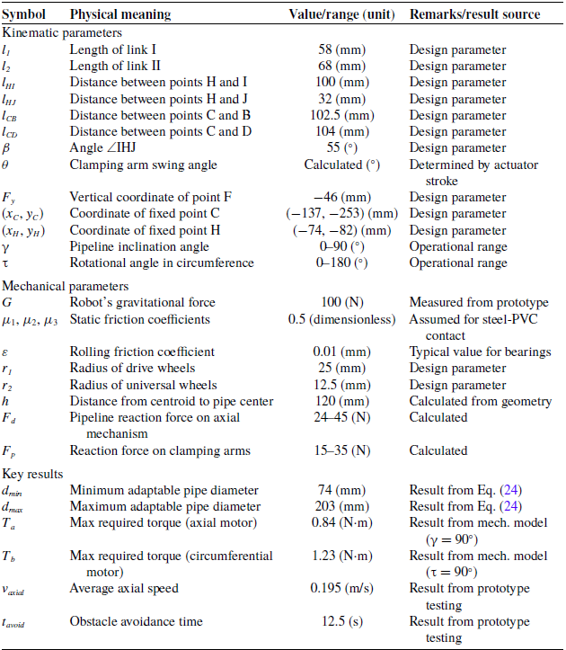
The following analysis is presented in symbolic form to ensure generality. The specific numerical values assigned to these symbols, which are based on the physical prototype, along with the primary computational results (such as the adaptable diameter range), are provided in the Appendix (Table A1) for reference.
A Cartesian coordinate system OXY is established with the center of the mounting bracket as the origin O, where the linear guide direction aligns with the X-axis and the perpendicular direction corresponds to the Y-axis. The positional relationships of robotic components are projected onto this coordinate system for geometric modeling, as shown in Figure 3.
Mathematical model of key points for the inspection robot.

The clamping mechanism is designed such that the two universal wheels and the drive wheel set form a 120° projected angle in the Cartesian coordinate system OXY. This specific geometry is fundamentally determined by static equilibrium principles. It ensures theoretically equal normal reaction forces at the three contact points with the pipeline, leading to uniform load distribution and a maximized stability domain for the robot. This optimized configuration is a prerequisite for the subsequent mechanical analysis, as it guarantees reliable clamping stability and efficient power transmission in both operational modes.
Key points are defined as follows: point A is Hinge point between the electric linear actuator I and the frame, point B is Hinge point between the electric linear actuator I and the clamping arm, point C is Hinge point between the clamping arm and the frame, point D is Center point of the universal wheel, point E is Center point of the axial drive wheel, point F is Hinge point of the slider, point J is Hinge point between the link II and the L-shaped link, point H is Hinge point between the L-shaped link and the frame, point I is Center point of the circumferential drive wheel, point Q: Hinge point between the axial drive unit and the link I, point M is Center point of the pipeline cross-section. The motion trajectory of the link I is defined by the moving points Q and F, while the link II’s trajectory is determined by points J and F.
First, the effects of the composite drive mechanism and the clamping mechanism on the robot’s adaptability to pipe diameters are analyzed separately. Then, the intersection of the results from both mechanisms is taken. Finally, the specific range of pipe diameters that the robot can adapt to is determined.
3.1. Adaptable pipeline diameter range of the compound drive mechanism
The compound drive mechanism, a critical component for motion switching in the robot, requires rigorous analysis of its adaptability to pipeline diameters. Let the angle between the line connecting points I and H and the positive X-axis be denoted as α.
The motion trajectory of point E is confined to a linear segment along the Y-axis. When the electric linear actuator II is fully extended (maximum stroke of 30 mm), the linear distance from point E to the origin O reaches 178 mm. Defining t as the vertical coordinate of point E, the permissible range of t is constrained by:
 \begin{equation} E_{y}=t\!\left\{\left.t\right| \right.\left.-178\leq t\leq -148\right\} \end{equation}
The motion trajectory of point Q is also confined to a linear segment along the Y-axis. Points E and Q are fixed relative to each other, with a vertical separation of 74 mm along the coordinate axis. Consequently, the vertical coordinate of point Q satisfies:
 \begin{equation} Q_{y}=t+74 \end{equation}
The motion trajectory of point F is confined to a linear segment along the linear guide. Since the linear guide is parallel to the X-axis and its vertical distance from the origin O is 46 mm, the vertical coordinate of point F remains constant:
 \begin{equation} F_{y}=-46 \end{equation}
The motion trajectories of points Q and F combined with the Y-axis can be geometrically represented as a right triangle, where the first link serves as the hypotenuse. Given that the motion trajectory of point F lies to the right of the Y-axis and the length of the first link is l 1 = 58 mm, the horizontal coordinate of point F can be expressed in terms of t as:
 \begin{equation} F_{x}=\sqrt{58^{2}-\left| t+74+46\right| ^{2}} \end{equation}
Since the motion trajectory of point I is a circular arc centered at the fixed point H, and the distance between points H and I is lHI = 100 mm, the coordinates of point I can be expressed as:
 \begin{equation} \left\{\begin{array}{l} I_{x}=-74-100\cos \alpha \\ I_{y}=-82-100\sin \alpha \end{array}\right. \end{equation}
The motion trajectory of point J is also a circular arc centered at the fixed point H. Given the distance between points H and J as lHJ
= 32 mm and the angles ∠IHJ = ∠I
 $^{\prime}$
H
 $^{\prime}$
J
 $^{\prime}$
= 55°, the coordinates of point J satisfy:
 \begin{equation} \left\{\begin{array}{l} J_{x}=-74+32\cos \left(180^{\circ}-\alpha -55^{\circ }\right)\\[3pt] J_{y}=-82-32\sin \left(180^{\circ}-\alpha -55^{\circ }\right) \end{array}\right. \end{equation}
The motion trajectories of points J and F, combined with the linear guide, form a right triangle where the second link serves as the hypotenuse. Given the length of the second link as l 2 = 68 mm, the geometric relationship satisfies:
 \begin{equation} {l_{2}}^{2}=\left(F_{x}-J_{x}\right)^{2}+\left(F_{y}-J_{y}\right)^{2}=68^{2} \end{equation}
The horizontal coordinate of point F can be expressed in terms of the angle as:
 \begin{equation} F_{x}=\sqrt{{l_{2}}^{2}-\left(F_{y}-J_{y}\right)^{2}}+J_{x} \end{equation}
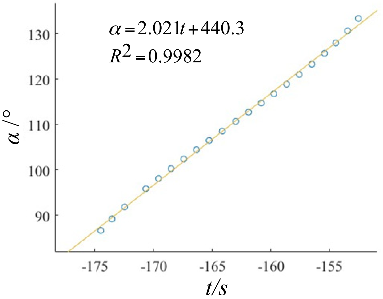
Through the representation of the x-coordinate of point F in Eqs. (4) and (8), a deterministic relationship between variables t and α in the form of an implicit function was derived. This implicit function was then input into MATLAB to generate a scatter plot, and curve fitting was subsequently performed using the fitting tool, as illustrated in Figure 4 Within reasonable error margins, the fitting results indicated a linear relationship between variables t and α. The fitted relationship can be expressed as:
 \begin{equation} \alpha =2.021t+440.3 \end{equation}
Relationship between t and α.

The coordinates of point I can be expressed in terms of t:
 \begin{equation} \left\{\begin{array}{l} I_{x}=74+100\cos \left(2.021t+440.3\right)\\[3pt] I_{y}=-82-100\sin \left(2.021t+440.3\right) \end{array}\right. \end{equation}
To calculate the adaptable pipe diameter range of the compound drive mechanism, it is necessary to determine the diameter of the circumcircle defined by the three points projected onto the Cartesian coordinate system OXY – specifically, the axial drive wheel and the two circumferential drive wheels – when the electric linear actuator II is retracted to its shortest length and extended to its longest length. Let the pipe diameter be d. Based on the positional relationships described above and the coordinates of point I expressed in terms of t in Eq. (10), the following equation can be established:
 \begin{equation} d=2\sqrt{I_{x}^{2}+I_{y}^{2}}-50 \end{equation}
The electric linear actuator II has a stroke of 30 mm. However, due to geometric constraints imposed by the lengths and angles of link I, link II, and the L-shaped link in the compound drive mechanism, the vertical coordinate of the axial drive wheel center (point E) becomes t = −162.5 mm when the electric linear actuator II is fully retracted. At this configuration, the circumcircle diameter is calculated as d = 74 mm, corresponding to a minimum adaptable pipe diameter of 74 mm for the compound drive mechanism. Conversely, when the electric linear actuator II is fully extended, the vertical coordinate of point E shifts to t = −178 mm, resulting in a circumcircle diameter of d = 304 mm, which defines the maximum adaptable pipe diameter. Therefore, the adaptable pipe diameter range of the compound drive mechanism is:
 \begin{equation} d\in \left[74,304\right] \end{equation}
3.2. Adaptable pipe diameter range of the clamping mechanism
To ensure effective pipe clamping and obstacle-crossing capabilities, the clamping mechanism must satisfy the following geometric condition: when the two clamping arms grip the pipe, the projected angles between the lines connecting the pipe center to the contact points of the universal wheels (fixed at the arm ends) and the Cartesian coordinate system OXY are required to maintain 120°.
Given that the angle between the line connecting points D and C and the negative horizontal axis of the coordinate system is defined as θ, with point C fixed at coordinates (−137, −253), the motion trajectories of points B and D are arc trajectories with fixed point C as the center. The distance between points C and B is specified as lCB = 102.5 mm, and between points C and D as lCD = 104 mm. Consequently, the coordinates of points D and B satisfy the following relationships:
 \begin{align}& \left\{\begin{array}{l} B_{x}=-137-102.5\cos \left(173^{\circ }-\theta \right)\\[3pt] B_{y}=-253+102.5\sin \left(173^{\circ }-\theta \right) \end{array}\right. \end{align}
 \begin{align}&\qquad \left\{\begin{array}{l} D_{x}=-137-104\cos \theta \\[3pt] D_{y}=-253-104\sin \theta \end{array}\right. \end{align}
Let B 1 be the extreme position of the electric linear actuator I when its stroke L 1 = 0 mm, with its coordinates measured as (−185.9, −163.17). Substituting the coordinates of B 1 into Eq. (13), the following result is obtained:
 \begin{equation} \theta _{1}\approx 111.5^{\circ} \end{equation}
Therefore, under this extreme position, the coordinates of point D 1 and the distance between the centers of the two universal wheels are determined as follows:
 \begin{align}& \left\{\begin{array}{l} D_{1x}=-137-104\cos \theta _{1}\approx -98.9\\[3pt] D_{1y}=-253-104\sin \theta _{1}\approx -349.8 \end{array}\right. \end{align}
 \begin{align}&\qquad\,\,\, l_{DD_{1}^{}}=2\times 98.9=197.8 \end{align}
Based on the geometric configuration of triangle MDDʹ, the maximum adaptable pipe diameter d of the clamping mechanism is determined as:
 \begin{equation} d_{\max }=2\times \left(\frac{\frac{l_{DD_{1}^{\prime}}}{2}}{\sin \frac{120^{\circ }}{2}}-\frac{25}{2}\right)=203.4 \end{equation}
Let B 2 represent the extreme position of the electric linear actuator I when its stroke L 1 = 100 mm; the coordinates of B 2 are determined as (−239.4, −247.5). Substituting the coordinates of B 2 into Eq. (13), the following result is obtained:
 \begin{equation} \theta _{2}\approx 170^{\circ} \end{equation}
Therefore, under this extreme position, the coordinates of point D 2 and the distance between the centers of the two universal wheels are determined as follows:
 \begin{align}& \left\{\begin{array}{l} D_{2x}=-137-104\cos \theta _{2}\approx -34.6\\[3pt] D_{2y}=-253-104\sin \theta _{2}\approx -271.2 \end{array}\right. \end{align}
 \begin{align}&\qquad\,\,\, l_{DD_{2}^{}}=2\times 34.6=69.2 \end{align}
Based on the geometric configuration of triangle MDDʹ, the minimum adaptable pipe diameter d of the clamping mechanism is determined as:
 \begin{equation} d_{\min }=2\times \left(\frac{\frac{l_{DD_{2}^{\prime}}}{2}}{\sin \frac{120^{\circ }}{2}}-\frac{25}{2}\right)=54.9 \end{equation}
Therefore, the adaptable pipe diameter range of the clamping mechanism is determined as:
 \begin{equation} d\in \left[54.9,203.4\right] \end{equation}
From Eqs. (12) to (23), the adaptable pipe diameter ranges calculated based on the compound drive mechanism and the clamping mechanism are combined by taking the intersection of the results from both mechanisms. After rounding the calculated diameter values, the theoretical adaptable pipe diameter range of the robot is determined as:
 \begin{equation} d\in \left[74,\,203\right] \end{equation}
The geometric parameters of the robot’s links, the key mechanical properties, and the primary results derived from the preceding analysis are consolidated in Table II. This table serves as a definitive reference for the specific numerical values assigned to the symbolic parameters used in the kinematic model and will be employed in the subsequent mechanical analysis.
4. Mechanical modeling and analysis of the robot
To move axially or rotate circumferentially, the robot must overcome resistance for inspection and obstacle avoidance. Therefore, calculating the minimum drive torque required for these two motion modes is crucial. The minimum drive torque is the lowest value required for stable and reliable robot motion.
4.1. Driving torque analysis in axial forward motion
To determine the required motor driving torque during axial forward inspection, the force analysis of the axial drive wheel system and universal wheels under clamped pipeline conditions is established, as illustrated in Figure 5.
The free-body diagram of robot moving axially along the pipe.

Key parameters include: point P is Robot’s center of gravity, F p1a , F p1b , F p2a , and F p2b are Pipeline support forces acting on four universal wheels during axial motion, F d1 and F d2 are Pipeline support forces on two axial forward drive wheels, Ta is Minimum required axial driving torque, T f1 and T f2 are Rolling resistance torques of axial drive wheels and universal wheels respectively, F f1 and F f2 are tangential forces exerted by the pipeline on axial drive wheels and universal wheels, γ is Pipeline inclination angle, G is Robot’s gravitational force, rolling friction coefficient for axial drive wheels and universal wheels: ε = 0.01 mm, radius of circumferential drive wheels is r 1 = 25 mm, radius of universal wheels is r 2 = 12.5 mm, static friction coefficients between wheels and pipe wall are μ 1 (axial drive wheels), μ 2 (universal wheels), Fd is Pipeline reaction force on the axial drive mechanism, F p1 and F p2 are reaction forces on clamping arms. During axial forward inspection, the reaction forces Fd and Fp remain invariant with respect to pipe diameter variations; these reaction forces are constant parameters in the mechanical model.
During axial inspection, the robot maintains force equilibrium at any instant. Specifically, the resultant force composed of the robot’s gravity and the pipe’s normal reaction force perpendicular to the pipe axis equals zero. Simultaneously, the static friction forces generated by the axial driving wheels and caster wheels clamping onto the pipe counterbalance the component of the robot’s gravity along the pipe axis. This yields the following equilibrium equations:
 \begin{equation} \left\{\begin{array}{l} F_{d}=F_{d1}+F_{d2}\\ F_{p1}=F_{p1a}+F_{p1b}\\ F_{p2}=F_{p2a}+F_{p2b}\\[3pt] \left(F_{p1}+F_{p2}\right) \cos 60^{0}=F_{d}+G\cos \gamma \\[3pt] F_{d}\mu _{1}+\left(F_{p1}+F_{p2}\right)\mu _{2}=G\sin \gamma \end{array}\right. \end{equation}
From Eq. (26), the following relationship can be derived:
 \begin{align} \left\{\begin{array}{l} F_{P1}=F_{P2}=\dfrac{G\sin \gamma +G\mu _{1}\cos \gamma }{2\mu _{2}+\mu _{1}}\\[10pt] F_{d}=\dfrac{G\sin \gamma -2\mu _{2}G\cos \gamma }{2\mu _{2}+\mu _{1}} \end{array}\right. \end{align}
 \begin{align} \left\{\begin{array}{l} F_{f1}=\left(F_{d1}+F_{d2}\right)\mu _{1}=F_{d}\mu _{1}\\[3pt] F_{f2}=\left(F_{p1}+F_{p2}\right)\mu _{2}\\[3pt] T_{f1}+T_{f2}=\varepsilon \left(F_{d1}+F_{d2}+F_{p1}+F_{p2}\right) \end{array}\right. \end{align}
To ensure normal inspection operations, the robot must overcome both the rolling friction torque generated by the axial driving wheels and the universal wheels during motion, as well as the downward gravitational component along the inclined pipe. With the static friction coefficients set as μ 1 = μ 2 = 0.5 and the gravitational force G = 100N, combining Eqs. (26) and (27), the minimum driving torque Ta required for the dual-axis geared motor can be expressed as:
 \begin{align} T_{a}&=T_{f1}+T_{f2}+F_{f1}\cdot r_{1}+F_{f2}\cdot r_{2}=\varepsilon \left(F_{d1}+F_{d2}+F_{p1}+F_{p2}\right)+F_{d}\mu _{1}\cdot r_{1}+\left(F_{p1}+F_{p2}\right)\mu _{2}\cdot r_{2}\nonumber\\ &=\varepsilon \left(\dfrac{G\sin \gamma -2\mu _{2}G\cos \gamma }{2\mu _{2}+\mu _{1}}+2\times \dfrac{G\sin \gamma +G\mu _{1}\cos \gamma }{2\mu _{2}+\mu _{1}}\right)+\dfrac{G\sin \gamma -2\mu _{2}G\cos \gamma }{2\mu _{2}+\mu _{1}}\mu _{1}\cdot r_{1}+2\nonumber\\ &\quad\times \dfrac{G\sin \gamma +G\mu _{1}\cos \gamma }{2\mu _{2}+\mu _{1}}\mu _{2}\cdot r_{2}\nonumber\\ & =\dfrac{3G\left(\sin \gamma +\mu _{1}\cos \gamma \right)\varepsilon }{2\mu _{2}+\mu _{1}}+\dfrac{G\mu _{1}r_{1}\left(\sin \gamma -2\mu _{2}\cos \gamma \right)}{2\mu _{2}+\mu _{1}}+\dfrac{2G\mu _{2}r_{2}\left(\sin \gamma +\mu _{1}\cos \gamma \right)}{2\mu _{2}+\mu _{1}}-G\varepsilon \cos \gamma \end{align}
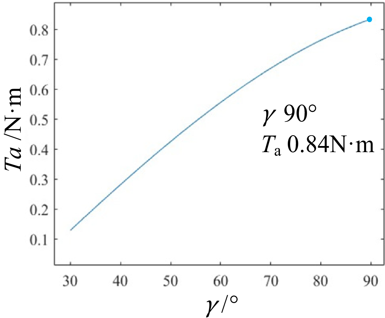
Using MATLAB, the above relationships were visualized to demonstrate the variation of the minimum required driving torque T a for the dual-axis geared motor with respect to the pipe inclination angle γ. As shown in Figure 6, (Note: Data for γ < 30° are omitted in the figure due to their negligible magnitudes, which lack practical significance.) the required axial drive torque Ta increases with the pipe inclination angle γ. When the pipe inclination angle γ = 90°, i.e., when the pipe is in a vertical orientation, the required drive torque reaches its maximum value of approximately 0.84 N·m. This maximum value represents the minimum design torque that the dual-shaft reduction motor must deliver to ensure stable operation across all inclination angles.
Relationship between γ and T a. .

4.1.1. Influence of pipe material properties on drive torque
The theoretical driving torque T a derived in Eq. (28) relies on the rolling friction coefficient (ε) and static friction coefficient (μ), which are physically dependent on the pipeline material’s elasticity and surface characteristics. According to Hertzian contact theory, the contact deformation between the robot’s wheels and the pipeline is governed by the equivalent Young’s modulus (E *). Non-metallic pipes, such as PVC or PE, typically possess a significantly lower Young’s modulus compared to metallic pipes. Under the same clamping force (Fn ), a lower modulus results in greater radial deformation at the wheel-pipe contact patch. This increased deformation enhances the hysteresis loss during motion, effectively increasing the rolling friction coefficient ε. Consequently, the minimum driving torque required for softer, non-metallic pipes will be theoretically higher than that for rigid metallic pipes due to this increased rolling resistance.
Furthermore, the static friction coefficient μ varies with surface roughness and environmental conditions. While μ does not directly quantify the resistive rolling torque, it determines the critical traction limit (F
friction
≤ μFN
) required to prevent wheel slippage. On smooth non-metallic surfaces where μ might be lower, the risk of slippage increases. However, the force analysis in Eq. (25) demonstrates that the proposed mechanism maintains a sufficient normal force through its clamping geometry. In this study, a conservative rolling friction coefficient (
 $\varepsilon$
= 0.01 mm) was selected to envelop the resistance characteristics of common industrial coatings. Although the theoretical torque demand may rise slightly for highly elastic materials, the selected motor (rated 4.9 N · m) provides a safety factor exceeding 5 relative to the calculated maximum requirement (0.84 N · m), ensuring operational robustness against material-induced variations in elasticity and friction.
4.2. Driving torque analysis in circumferential rotation mode
A mechanical analysis of the circumferential drive wheel system and caster wheel system during clamping and rotating around the pipe is established, as illustrated in Figure 7. Point M represents the robot’s rotational center, coinciding with the pipe’s cross-sectional centroid. Key parameters include:
The free-body diagram of robot rotating circumferentially around the pipe.

 $F^{\prime}_{p1}$
and
 $F^{\prime}_{p2}$
are normal support forces exerted by the pipe on the left and right clamping arms during circumferential rotation. F
n1 and F
n2 are normal forces from the pipe acting on the left and right circumferential drive wheels, respectively.
 $F^{\prime}_{f1}$
and
 $F^{\prime}_{f2}$
are tangential reaction forces from the pipe on the circumferential drive wheel and universal wheel.
 $T^{\prime}_{f1}$
and
 $T^{\prime}_{f2}$
are rolling resistance torques generated by the circumferential drive wheel and universal wheel. Tb
is the minimum required driving torque of the DC reduction motor. ω is between the lines of action of the reactive forces F
n1 and F
n2 and the robot’s symmetry axis. τ is the angular deviation between the robot’s symmetry axis and the gravitational direction.
The rolling friction coefficient of the circumferential drive wheel is set as
 $\varepsilon$
= 0.01 mm, and μ
3 denotes the static friction coefficient between the circumferential drive wheel and the pipe wall. The parameter represents the distance from the robot’s center of gravity to the rotational center. To ensure that the projected angle between the contact points of the universal wheels (fixed to the two clamping arms) and the pipe center onto the Cartesian coordinate system OXY is 120°, the angular parameter ω (defined as the angle between the reaction forces and the robot’s symmetry axis) varies with the pipe diameter d. This occurs because the position of the pipe center relative to the robot shifts when clamping pipes of different diameters. The relationship between ω and d is derived from the coordinates of the pipe center before and after the robot’s motion mode transition.
The radius of the circumferential drive wheel is 25 mm. Prior to the motion mode transition, the coordinates of the pipe center M in the Cartesian coordinate system are determined from Eq. (9) as follows:
 \begin{equation} M_{y1}=t-25-\frac{d}{2}=\frac{\alpha -440.3}{2.021}-25-\frac{d}{2} \end{equation}
From Eq. (4), the coordinates of point I, the center of the circumferential drive wheel, can be expressed in terms of α. When the robot clamps a pipe of identical diameter and undergoes motion mode transition, the position of the pipe’s cross-sectional center remains unchanged. By analyzing the contact condition between the circumferential drive wheel and the pipe wall and combining Eq. (29), it is established that α and the pipe diameter d exhibit an implicit functional relationship, as shown in Eq. (30):
 \begin{equation} I_{x}+I_{y}=\left(-74-100\cos \alpha \right)^{2}+\left[-82-100\sin \alpha -M_{y1}\right]^{2}=\left(\frac{d}{2}+25\right)^{2} \end{equation}
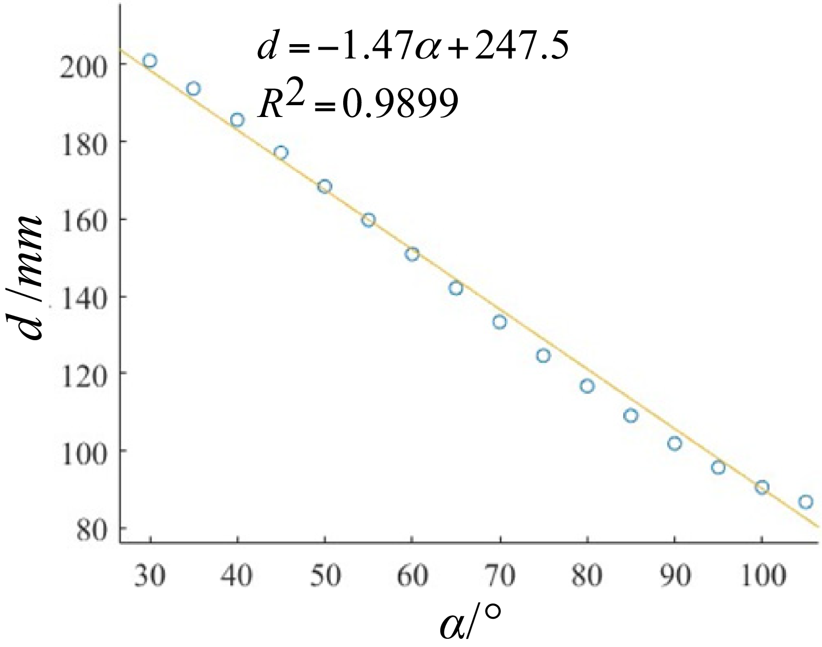
This implicit function was input into MATLAB to generate a scatter plot of the relationship. A curve-fitting tool was then applied to approximate the functional form, with the results illustrated in Figure 8.
Relationship between α and d.

Within reasonable error margins, the fitting results indicate a linear relationship between the variable α and the pipe diameter d. The fitted relationship can be expressed as:
 \begin{equation} \sin \omega =\frac{I_{x}}{\frac{d}{2}+25}=\frac{74+100\cos \left(\frac{247.45-d}{1.47}\right)}{\frac{d}{2}+25} \end{equation}
During rotational obstacle-avoidance maneuvers, the robot maintains force equilibrium at any instant. Specifically:
Vertical Force Balance (perpendicular to the pipe axis): the component of the robot’s gravitational force perpendicular to the pipe is balanced by the corresponding normal reaction force exerted by the pipe.
Tangential Moment Balance (at wheel-pipe contact points): the static friction torque generated by the circumferential drive wheel and universal wheel clamping onto the pipe counteracts the gravitational torque induced by the angular deviation τ between the robot’s symmetry axis and the gravitational direction.
This dual equilibrium condition ensures stable rotational motion and is mathematically expressed as:
 \begin{equation} \left\{\begin{array}{l} F_{p1}^{\prime}\times 66\% \cos60^{\circ}+F_{p2}^{\prime}\times 66\% \cos60^{\circ}=\left(F_{n1}+F_{n2}\right)\cos \omega +G\cos \tau \\[5pt] Gh\sin \tau =\dfrac{\left(F_{n1}+F_{n2}\right)\mu _{3}d}{2}+\dfrac{d\left(F_{p1}^{\prime}+F_{p2}^{\prime}\right)\mu _{2}}{2} \end{array}\right. \end{equation}
From Eq. (32), the following relationship can be derived:
 \begin{equation} \left\{\begin{array}{l} F_{n1}+F_{n2}=\dfrac{2G\left(\dfrac{h\times \sin \tau }{\varphi }-\cos \tau \mu _{2}\right)}{\mu _{3}+2\mu _{2}\cos \omega }\\[12pt] F_{p1}^{\prime}=F_{p2}^{\prime}=\dfrac{2\mathit{Gh}\cos \omega \sin \tau }{\varphi \mu _{3}+2\varphi \mu _{2}\cos \omega }+\dfrac{\mu _{3}G\cos \tau }{\mu _{3}+2\mu _{2}\cos \omega } \end{array}\right. \end{equation}
To ensure successful rotational obstacle avoidance, the circumferential drive motor must overcome both the rolling friction torques from the circumferential drive wheel system and universal wheel auxiliary system, as well as the gravitational torque generated by the elevation of the robot’s center of gravity, which causes angular deviation (τ) of the symmetry axis from the gravitational direction. The minimum driving torque T b required for the DC reduction motor must satisfy:
 \begin{align} T_{b}&=\dfrac{T_{f1}^{\prime}+T_{f2}^{\prime}+Gh\sin \tau }{2}=\dfrac{\varepsilon \left(F_{n1}+F_{n2}+F_{p1}^{\prime}+F_{p2}^{\prime}\right)+Gh\sin \tau }{2}\nonumber\\& =\dfrac{\varepsilon \left[\dfrac{2G\left(\dfrac{h\times \sin \tau }{\varphi }-\cos \tau \mu _{2}\right)}{\mu _{3}+2\mu _{2}\cos \omega }+2\times \left(\dfrac{2\mathit{Gh}\cos \omega \sin \tau }{\varphi \mu _{3}+2\varphi \mu _{2}\cos \omega }+\dfrac{\mu _{3}G\cos \tau }{\mu _{3}+2\mu _{2}\cos \omega }\right)\right]+Gh\sin \tau }{2} \end{align}
During pipe clamping, the robot actively adjusts the positions of its clamping arms to ensure that the projected angle between the contact points of the universal wheels and the pipe’s centroid on the Cartesian coordinate system OXY is maintained at 120°. Consequently, when clamping pipes of varying diameters, the distance h from the robot’s center of gravity to the pipe’s cross-sectional centroid remains approximately constant, with h = 120 mm. Using the static friction coefficient μ 3 = 0.5, Eq. (35) was visualized in MATLAB to analyze the relationship between the required driving torque Tb , pipe diameter d, and the rotational angle τ of the pipe’s centroid. As shown in Figure 9, to ensure the robot can overcome the gravitational torque throughout the entire circumferential rotation process, the drive motor must be capable of providing a torque no less than this maximum value. Analysis indicates that the maximum torque occurs at τ = 90°, where Tb reaches a peak value of approximately 1.23 N · m. Thus, the minimum drive torque required for the DC gear motor is approximately 1.23 N · m.
Relationship between τ, d and T b .

5. Motion simulation of inspection robot
To accurately simulate actual working conditions, a kinematic simulation of the robot was conducted using Adams software, focusing on analyzing the maneuverability of axial movement and circumferential rotation along the pipeline outer wall. This primarily included performance evaluations of inclined-surface climbing and rotational obstacle-avoidance capabilities.
5.1. Analysis of climbing performance on inclined pipelines
Due to terrain constraints, pipelines may be installed with certain inclination angles during actual deployment, which imposes higher requirements on the climbing capability of inspection robots.
Different tilt angles of the pipeline were achieved by adjusting the components of gravitational acceleration along coordinate axes. After configuring the simulation environment, the inspection process along inclined pipelines was simulated. Numerical values of centroid deflection angles were obtained for the robot operating on 110 mm outer diameter pipelines with 60° and 90° tilt configurations, as shown in Figure 10.
Simulation analysis of robot climbing performance on inclined pipelines.

As can be seen from the analysis results, during the inspection process where the robot clamps onto the pipeline and moves axially, the centroid deflection angle exhibits significant fluctuations when the robot initially grips the pipeline but rapidly stabilizes into a steady-state phase. When operating on pipelines inclined at 60°, the centroid deflection angle in the steady-state phase remains below 5°, while on pipelines inclined at 90°, this angle does not exceed 7°. Based on the overall data, the robot demonstrates stable operation on pipelines with inclination angles ranging from 0° to 90°.
5.2. Analysis of circumferential rotation obstacle avoidance performance
Under real-world working conditions, when the robot performs inspections on horizontal pipelines and encounters obstacles such as T-shaped pipeline junctions ahead, it requires a maximum rotation of 180° to complete the obstacle avoidance maneuver. In this simulation, a motion path was designed for the robot to rotate from the lowest to the highest point of the pipeline. The circumferential rotation capability of the robot was evaluated by analyzing the displacement of its centroid position and centroid velocity during this motion. The simulation of the robot rotating from the lowest to the highest point on a horizontal pipeline is illustrated in Figure 11(a).
Simulation analysis of rotating obstacle avoidance for robots in horizontal pipeline.

Through post-processing, the velocity of the robot’s centroid along the non-rotational axis and its displacement along the rotational axis direction during circumferential rotation on a horizontal pipeline were plotted and exported, as shown in Figure 11(b). During the circumferential rotation motion on the horizontal pipeline, the velocity of the centroid along the non-rotational axis and its positional variation along the rotational axis exhibited significant fluctuations when the robot initially contacted the pipeline but quickly stabilized into a steady-state phase. Throughout the motion, gravity performed negative work. In the time interval of 0–6.5 s, the displacement of the robot’s centroid along the non-rotational axis changed dramatically due to the gradually increasing gravitational torque generated by the gravity acting on its centroid, reaching a maximum around 6.5 s. During 6.5–13 s, both the centroid displacement and velocity variations stabilized as the gravitational torque progressively decreased, attaining a minimum around 13 s. Over the entire process, the robot’s velocity remained stable, with a maximum centroid displacement of approximately 0.5 mm from its initial position. Given the robot’s total length of 270 mm, the relative displacement ratio was about 1.85‰.
In practical working conditions, when encountering front obstacles such as T-shaped pipes on vertical pipelines, the robot needs to perform circumferential rotational motion along the pipe. In this simulation, a motion path was designed for the robot to rotate from the right side to the left side of the pipe. The circumferential rotational capability of the inspection robot was validated by analyzing data such as the radial deflection of the centroid position and centroid velocity, as shown in Figure 12(a).
Simulation analysis of rotating obstacle avoidance for robots in vertical pipeline.

Through post-processing, the velocity of the robot’s centroid perpendicular to the rotational axis and its radial deflection relative to the rotational axis during circumferential rotation on the vertical pipe were plotted and exported, as shown in Figure 12(b). During the circumferential rotation along the vertical pipe, the centroid velocity along the non-rotational axis exhibited significant fluctuations at initial pipe contact, followed by rapid stabilization. Throughout the motion, the velocity profile remained relatively smooth. Since the preset motion direction was perpendicular to the gravitational direction, a slight downward slippage of approximately 1.6 mm along the pipe occurred over the 13-second operation period. Given the robot’s total length of 270 mm, this corresponds to a deflection ratio of approximately 5.93‰. The simulation results confirm that the robot maintains stable operational performance during circumferential rotation around the pipe, demonstrating effective obstacle-avoidance capability through circumferential rotational motion.
6. Prototype development and experiments
Prototype fabrication and testing are crucial for evaluating the structural rationality and operational feasibility of the robot. Based on the robot’s transmission scheme design and the previously calculated minimum driving torques required for its two motion modes, the dual-shaft worm gear reducer motor (Model 5882-50ZY) and the single-shaft DC gear motor (Model 36GP-36ZY) were selected to power the robot’s axial and circumferential driving mechanisms, respectively. The performance parameters of these two DC gear motors are summarized in Table I.
Drive motor and its parameters.

The robot prototype weighs 7.5 kg, with its electrical components powered by a battery. The physical prototype of the external pipeline inspection robot is illustrated in Figure 13.
The physical prototype model of the robot.

6.1. Pipe diameter adaptability test
To rigorously evaluate the robot’s adaptability across its theoretical design range of 74–203 mm, kinematic verification and axial locomotion tests were conducted on four distinct PVC pipelines with outer diameters of 75, 110, 160, and 200 mm. The physical experimental setups, illustrating the robot’s adaptive clamping posture on each diameter, are presented in Figure 14. These specifications were selected to represent the lower bound, intermediate gradients, and upper bound of the operational scope, ensuring a comprehensive assessment of the clamping mechanism’s versatility. The adaptation to these varying curvatures was achieved by precisely regulating the extension of the Electric Linear Actuator II based on the kinematic model established in Section 3. For the compact 75 mm pipeline (Figure 14(a)), the actuator was fully retracted to fold the clamping arms inward; conversely, for the 160 and 200 mm pipelines (Figures 14(c) and 14(d)), the actuator was progressively extended to maximize the arm opening, ensuring the universal wheels maintained the optimal 120° contact geometry required for stable clamping.
Experimental setup of the robot clamping onto pipelines with varying outer diameters.

Quantitative performance tests involved repeated axial traversals over a fixed 1.0-m distance for each diameter to minimize stochastic errors. The temporal data for each trial was recorded and converted into average velocity to assess locomotion consistency. The consolidated results, presented in Table II, indicate a high degree of stability across the entire diameter spectrum. The robot demonstrated robust locomotion capabilities on all four pipeline specifications, with standard deviations of speed remaining below 0.03 m/s, corroborating the reliability of the transmission system under varying geometric constraints.
Axial movement velocity test results across varying pipe diameters.

A comparative analysis of the velocity data reveals a remarkable consistency in performance. While the average speeds for the 75 and 110 mm pipes were identical (0.195 m/s), a marginal attenuation was observed as the diameter increased further, reaching 0.193 m/s for the 160 mm pipe and 0.191 m/s for the 200 mm pipe. This slight deceleration (approximately 2.1% total drop) is physically consistent with the increased viscoelastic deformation of the rubber wheel coating induced by the altered contact patch geometry on larger curvatures. Despite this minor variation, the robot maintained stable traction without slippage across all tests. This performance validates the core advantage of the proposed dual-slider mechanism: by decoupling the clamping range from the drive unit, it ensures uniform normal force distribution and consistent traction regardless of the pipe diameter, thereby proving its effectiveness for complex industrial pipeline networks.
6.2. Evaluation of climbing performance and stability on inclined pipelines
To comprehensively evaluate the robot’s performance in inclined pipelines, a series of climbing experiments were conducted on a PVC pipeline with an outer diameter of 110 mm. The experiments focused on three key performance indicators: climbing speed stability, slippage analysis, and maximum load-bearing capacity across inclination angles of 0°, 30°, 45°, 60°, and 90°. The climbing process is illustrated in Figure 15.
Robotic incline climbing capability test.

Tests demonstrated that the robot maintained stable operation in the 90°-inclined pipeline, validating its robust adaptability to complex operational conditions.
6.2.1. Climbing speed and slippage analysis
The robot was positioned at the bottom of the pipeline, and its climbing velocity was recorded after reaching a steady state. The relationship between the axial speed and the inclination angle (γ) is illustrated in Figure 16.
Relationship between axial speed and pipeline inclination angle.

The results indicate a non-linear decrease in speed as the inclination increases, dropping from 0.195 m/s at 0° (horizontal) to 0.111 m/s at 90° (vertical). To quantify the stability of the locomotion, the slip ratio (λ) was introduced and calculated as follows:
 \begin{equation} \lambda =\frac{v_{\textit{ideal}}-v_{exp}}{v_{\textit{ideal}}}\times 100\% \end{equation}
where v ideal is the theoretical speed determined by the wheel rotation speed and wheel radius, and v exp is the measured experimental speed.
The analysis reveals two primary factors contributing to the speed reduction (∼43%) at vertical states:
-
1. Motor Hard Mechanical Characteristic: As analyzed in Section 4.1 (Driving Torque Analysis), the required driving torque Ta increases with the gravitational component G sinγ. The selected DC motor (Model 5882-50ZY) exhibits a characteristic drop in rotational speed as the output torque increases.
-
2. Micro-slippage: At γ = 90°, the slip ratio reaches approximately λ ≈ 15%. This is primarily caused by the elastic deformation of the rubber coating on the wheels and micro-slippage at the PVC interface under high traction loads. However, no continuous macroscopic slippage or "run-away" incidents were observed, confirming that the friction provided by the clamping mechanism is sufficient for vertical climbing.
6.2.2. Stability and anti-overturning performance
Stability during climbing was evaluated by monitoring the robot’s posture. Consistent with the simulation results in Figure 10, the robot maintained a stable pose throughout the climbing process. Even at 90°, the deviation of the robot’s geometric center from the pipe axis remained minimal. The six-point wheel-clamping mechanism (comprising 2 driving wheels and 4 universal wheels) proved effective in counteracting the overturning moment (M overturn ) generated by the offset of the center of gravity. The clamping force ensured that the normal contact forces remained positive at all points, preventing any local detachment or instability.
6.2.3. Theoretical maximum load capacity analysis
To assess the robot’s payload potential, the maximum load capacity was estimated based on the mechanical model established in Eq. (28) and the motor parameters listed in Table I.
At a 90° inclination, the required torque for the robot’s self-weight (7.5 kg) is calculated as T req ≈ 0.84 N·m (see Figure 6). Given the motor’s rated continuous torque of T rated = 4.9 N·m, the available torque margin is:
 \begin{equation} T_{\textit{margin}}=T_{\textit{rated}}-T_{req}=4.9-0.84=4.06\,\mathrm{N}\, \mathrm{m} \end{equation}
This substantial torque margin suggests that, limited strictly by motor power, the robot could theoretically support a significantly higher payload. However, in practical applications, the load capacity is constrained by the static friction coefficient between the wheels and the pipe (μ ≈ 0.5). Conservative estimates indicate the robot can carry an additional payload of 5–8 kg (approximately 100% of its own weight) on vertical PVC pipes without experiencing gross slippage. This capacity meets the requirements for carrying standard inspection sensors and cameras.
6.2.4. Comparative analysis: simulation vs. physical prototype
To assess the fidelity of the Adams kinematic simulation presented in Section 5.1, a rigorous comparative analysis was conducted between the simulation predictions and the physical experimental results regarding climbing stability and kinematic performance. In terms of stability characteristics, the experimental observations strongly corroborate the simulation predictions. The simulation indicated that the robot’s centroid deflection angle would stabilize rapidly, maintaining a deviation of less than 5° for 60° inclinations and approximately 7° for 90° inclinations. Consistent with this, the physical prototype exhibited no periodic swaying or tendency to detach throughout the vertical climbing tests. The six-point clamping mechanism effectively suppressed the overturning moment, maintaining a posture aligned with the steady-state phase observed in the simulation. This qualitative and quantitative agreement confirms the validity of the rigid-body dynamic model in characterizing the robot’s structural stability.
Conversely, a quantitative comparison of the climbing velocity reveals a distinct divergence between the ideal simulation model and physical reality. While the kinematic simulation – constrained by constant angular velocity inputs – predicted a constant axial speed regardless of inclination, the experimental data (Figure 16) demonstrates a speed attenuation of approximately 43% (from 0.195 to 0.111 m/s) as the inclination increases from 0° to 90°. This discrepancy highlights physical constraints inherent to the real-world system that were omitted in the ideal kinematic model: specifically, the electromechanical coupling where DC motors inherently reduce speed under increased gravitational load (Gsinγ) and the cumulative effect of micro-slippage (λ ≈ 15%) at the viscoelastic wheel-pipe interface. In conclusion, while the simulation accurately verified the structural rationality and stability limits of the mechanism, the experimental results provided critical insights into the dynamic efficiency losses caused by real-world electromechanical and tribological factors.
6.3. Rotational obstacle avoidance and traversal capability test
The robot’s rotational obstacle avoidance capability distinguishes it from conventional inspection robots. To validate this functionality, a PVC pipe system with a reducing tee fitting (110 mm main pipe diameter, 75 mm branch pipe diameter) was constructed as the test platform, as shown in Figure 17.
Obstacle avoidance and traversal maneuvering sequence of the robot.

When encountering the reducing T-junction obstacle (Figure 17), the robot first activated its dual-slider multi-link mechanism for locomotion mode transition (Figure 17(a)). Subsequently, the circumferential drive mechanism rotated the robot along the pipe until optimal positioning was achieved, followed by secondary mode switching (Figure 17(b–d)). Finally, the robot successfully navigated through the obstacle via circumferential propulsion (Figures 17(e) and 17(f)), thereby completing the integrated obstacle avoidance and negotiation process. This entire sequence was completed within 12.5 s. Based on prototype testing, it can be concluded that the robot is capable of completing obstacle avoidance and obstacle crossing when encountering T-shaped pipes with a diameter no greater than 3/4 of the diameter of the inspection pipe.
6.4. Comparative analysis and discussion
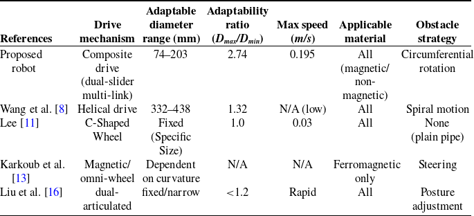
To rigorously validate the advanced performance of the proposed robot, a comparative analysis was conducted against representative pipeline inspection robots reported in recent literature. The comparison focuses on key performance metrics, including the drive mechanism type, adaptable pipe diameter range, adaptability ratio (defined as the ratio of maximum to minimum adaptable diameter), maximum inspection speed, and obstacle negotiation strategy. By benchmarking against these established systems, the specific engineering advantages of the novel dual-slider mechanism in balancing structural compactness with wide-range versatility are clearly elucidated. The detailed comparison is presented in Table III.
Performance comparison between the proposed robot and existing pipeline inspection robots.

6.4.1. Superior diameter adaptability
As shown in Table III, the proposed robot achieves an adaptability ratio of 2.74, which is significantly higher than that of the helical drive robot (1.32) [Reference Wang, Wang, Zhou, Feng and Wang8] and the fixed-diameter C-shaped robot [Reference Lee11]. The widely cited helical drive mechanism typically requires a complex frame adjustment to change diameters, whereas the proposed dual-slider multi-link mechanism allows for continuous in-situ adjustment. By linearizing the relationship between the slider displacement and the clamping arm angle (as verified in Figure 4), the robot can cover a wide range of 74–203 mm without changing parts, making it suitable for piping systems with varying cross-sections.
6.4.2. Efficiency and speed advantage
In terms of inspection efficiency, the proposed robot achieves an average axial speed of 0.195 m/s, which is approximately 6.5 times faster than the C-shaped robot (0.03 m/s) [Reference Lee11].
Mechanism Reason: Helical drive robots [Reference Wang, Wang, Zhou, Feng and Wang8] often suffer from low transmission efficiency due to the substantial sliding friction component inherent in their spiral motion. In contrast, our robot employs a direct wheel-drive method for axial motion. The dual-slider mechanism ensures that the normal force on the wheels is optimized (maintaining the 120° clamping angle), maximizing traction while minimizing unnecessary friction loss.
6.4.3. Material independence and obstacle crossing
Unlike magnetic adhesion robots [Reference Xu, Wang, Du, Bao, Hu and Yuan9, Reference Karkoub, Bouhali and Sheharyar13] that are strictly limited to ferromagnetic pipelines, the wheel-clamping force generated by our mechanism is independent of pipe material, allowing effective operation on PVC, PE, and stainless steel pipes. Furthermore, compared to the dual-articulated robot [Reference Liu, Li and Zhong16], which relies on posture adjustment to cross obstacles – a method that can be unstable on vertical pipes – our robot’s circumferential rotation strategy guarantees that the center of mass remains close to the pipe wall, providing superior stability during obstacle negotiation as evidenced in the simulation (Figure 12).
Conclusions
This paper presents a novel wheel-clamping external pipeline inspection robot capable of active circumferential rotation. The proposed design demonstrates significant advantages in adaptability, mobility, and obstacle-crossing capability when compared to existing pipeline inspection robots, as quantitatively validated through mechanical analysis, simulation, and prototype experiments.
-
1. Superior Diameter Adaptability and Range: The proposed wheel-clamping robot operates effectively on both metallic and non-metallic pipelines, overcoming the material dependency of magnetic adhesion robots such as the inchworm-mimetic robot by Khan et al. [Reference Karkoub, Bouhali and Sheharyar13], which is confined to ferromagnetic surfaces. Furthermore, the robot achieves an adaptable pipeline diameter range of 74–203 mm. The adaptability ratio of 2.74 represents a significant improvement over the typical ratio of ∼ 1.3 found in helical drive robots [Reference Wang, Wang, Zhou, Feng and Wang8] and the fixed structures of C-shaped robots [Reference Lee11].
-
2. Enhanced Mobility and Obstacle Negotiation through Innovative Mechanism: The core innovation lies in the dual-slider multi-link mechanism, which enables rapid and reliable switching between axial advancement and circumferential rotation. This functionality grants the robot unique in-situ obstacle avoidance capabilities. When encountering T-shaped pipeline obstacles, the robot successfully navigates by rotating around the pipe circumference, a feature not effectively addressed in many conventional designs like the three-wheeled model by Li et al. [Reference Li, Huang and Fang12]. Experiments confirm the robot’s ability to cross T-junctions where the branch diameter is no greater than three-quarters of the main pipe’s diameter, completing the entire avoidance and traversal process in approximately 12.5 s. With a maximum speed of 0.195 m/s, the robot demonstrates significantly higher inspection efficiency compared to similar external climbers, such as the C-shaped robot, which operates at approximately 0.03 m/s [Reference Lee11]. Furthermore, the proposed dual-slider mechanism enables active circumferential rotation, distinguishing it from articulated designs [Reference Liu, Li and Zhong16] that rely solely on linear posture adjustments, thereby providing superior stability during complex obstacle negotiation.
-
3. Validated Stability and Climbing Performance: Mechanical modeling determined the minimum driving torques for the dual-shaft and DC reduction motors to be 0.84 and 1.23 N·m, respectively. Prototype testing validated stable axial movement at an average speed of 0.195 m/s and reliable operation on pipelines with inclinations from 0° to 90°, demonstrating robust performance across various orientations. The robot’s centroid deflection angle remained below 7° during inclined pipeline climbing, confirming operational stability. This comprehensive validation under rigorous conditions, including vertical (90°) pipelines, demonstrates a level of operational robustness that is often only partially addressed in prior works, such as the collision-resistant wheel-clamping robot by Duanmu et al. [Reference Duanmu, Chen and Zheng15], which emphasized real-time posture correction but may not have demonstrated capabilities across such a wide range of inclinations.
In summary, the proposed robot overcomes key limitations of prior art, including material dependency and limited obstacle-crossing strategies, by integrating a novel composite drive mechanism with a versatile wheel-clamping design. The experimental results, backed by quantitative data on speed, torque, inclination adaptability, and obstacle-crossing capability, affirm that this design provides a more comprehensive and adaptable solution for inspection tasks in complex pipeline environments.
Financial support
This work was funded by the Open Project of Anhui Province Key Laboratory of Special and Heavy Load Robot (No. TZJQR002-2022), the Open Project of China International Science and Technology Cooperation Base on Intelligent Equipment Manufacturing in Special Service Environment (No. ISTC2022KF07), and the Open Project of Anhui Province Engineering Laboratory of Intelligent Demolition Equipment (No. APELIDE2023A001).
Competing Interests
The authors declare no competing interests exist.
Ethical approval
Not applicable.
Declaration of AI use
During the preparation of this work, we used Gemini (Google Large Language Model) in order to assist with the translation and language polishing of specific sentences to enhance clarity and readability. After using this tool, we reviewed and edited the content as needed and take full responsibility for the content of the publication.
Author contribution
Authors equally contributed to the writing of this paper.
Appendix
Nomenclature, parameter values, and key results