I. INTRODUCTION
Nowadays, with the wide application of digital electronics devices, the quiet electromagnetic environment required by astronomical observation is increasingly being damaged, especially at low-frequency band of <1 GHz. Increasing astronomical observatories employ low insertion loss filter between feed and first-stage low-noise amplifier (LNA) to mitigate the low-frequency interference signals and keep the first-stage LNA from saturation distortion [Reference Yu1]. Extremely small passband insertion loss and high stop-band rejection are the key specifications as filter locating in front of the first-stage LNA of receiver. High-temperature superconducting (HTS) filter [Reference Yu1–Reference Zhang3] is a feasible choice due to its small insertion loss, steep skirt slop, and high stop-band rejection, which has been employed by some observatories [Reference Li2]. The disadvantage of HTS filter is that it needs to be cooled down to cryogenic temperature (e.g. 40 K) by using a set of complicated cryogenic cooling system. In addition, expensive and long-periodic film processing technique (film growth, photolithography, and ion-beam milling, etc.) limit the use of HTS filter, especially for array telescopes with giant components demand (e.g. Square Kilometer Array project).
This paper presents an ultra-low-loss high-pass filter for L band astronomical receiver to suppress radio frequency interference (RFI) in low frequencies of <900 MHz, and its specifications are to meet the requirement of 6 m telescope of California Institute of Technology (Caltech), which locates in the city of Pasadena and runs at room temperature. The high-level low-frequency RFI arising from mobile communication, TV signal, and broadcast promote astronomers there to search a low-loss high-pass filter running at room temperature for receiver frontend. This high-pass filter was asked to meet the following requirements: 3 dB cutoff frequency of 890 MHz, exceeding 1.8 GHz passband, <0.2 dB passband insertion loss, >20 dB stop-band rejection at 700 MHz, and >20 dB return loss. Computer-aid design analysis reveals that this filter needs at least seven poles for Chebyshev topology to meet the stop-band rejection specification mentioned above. Three capacitors in series, four shunt inductors, and a piece of microstrip circuit board constitute the building blocks of this filter. Several methods were employed to reduce filter noise. For capacitors and circuit board, we chose the commercial devices with resistance loss as low as possible. The brass filter box and cover are plated with gold to reduce resistance losses. Specially, four shunt inductors are actualized by fabricating air-core short-circuit coaxial cable inductors in the filter box body, and the quality factor of these cable inductors is up to 762.2 and 1046, respectively, at 1.4 GHz. Comparing with common low-loss chip inductors, these fabricated cable inductors contribute less noise to the filter. S parameters measurement reveals that this high-pass filter achieved <0.16 dB insertion loss, >20 dB return loss in passband up to 1.9 GHz, and >20 dB stop-band rejection at 700 MHz. The comparison measurement for a LNA noise and gain with and without this high-pass filter in front was carried out by NFA8975A, the noise temperature increased by nearly 8 K in passband.
II. FILTER DESIGN
This high-pass filter is based on a seven-pole Chebyshev structure, and the synthesis of Chebyshev filters is well known, and the frequency and impedance transformation procedure used here can be found in [4].
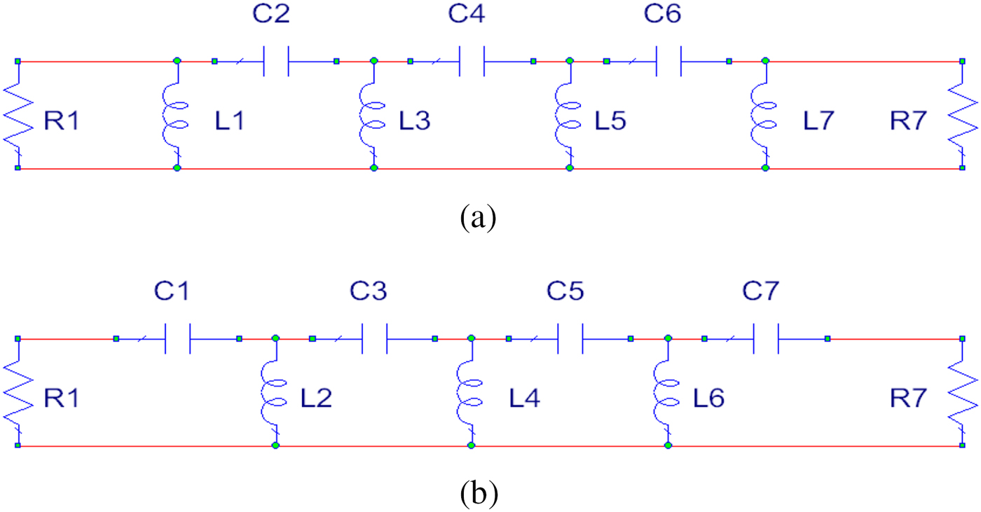
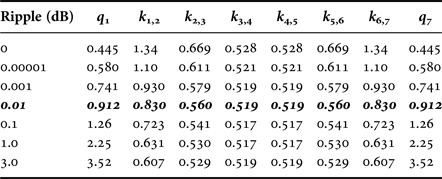
There are two kinds of circuit structure for seven-pole Chebyshev high-pass filter shown in Fig. 1. For the circuit structure (a), the shunt inductor arms of L1 and L7 are at the two ends of the circuit. Comparatively, the series capacitor arms of C1 and C7 are at the two ends for the structure (b). In this paper, we try to fabricate air-core short-circuit coaxial cable inductors in the filter box body, which quality factors (Q) are extremely high compared with general surface-mounting devices. Structure (a) was adopted because it employs fewer chip capacitors. The passband ripples depending on the normalized modular constant k and modular value q of the seven-pole non-zero Chebyshev high-pass filter are tabulated in Table 1. The 0.01 dB passband ripples is selected to trade-off small ripples and steep skirt slop, as it is known that the larger passband ripples the steeper skirt slop.
Two types circuit structures of seven-pole non-zero Chebyshev high-pass filters. R1 and R7 is source and load resistor, respectively; (a) shunt inductors arms are at the two ends of the circuit; (b) series capacitors arms are at the two ends of the circuit. L1, L2–L7 are shunt inductors and C1, C2–C7 are series capacitors.

The k and q values for various passband ripples for seven-pole no-zero filter.

The bold numerical numbers represent the design parameters for the proposed filter.
The closed form relations of capacitance, inductance, and source resistance shown in Fig. 1(a) with k and q in Table 1 can be expressed by [4]:
 $$\left( {{{R_1} / {L_1}}} \right) = q_1 \omega _{3\,{\rm dB}}, $$
 $${1 / {\left( {L_i C_{i + 1}} \right)^{1/2} = \left( {{1 / {k_{i,i + 1}}}} \right)\omega _{3\,{\rm dB}},}} \quad i = 1,3,5,$$
 $${1 / {\left( {C_j L_{j + 1}} \right)^{1/2} = \left( {{1 / {k_{j,j + 1}}}} \right)\omega _{3\,{\rm dB}},}} \quad j = 2,4,6,$$
where 3 dB-down angular frequency ω 3 dB is equal to 2πf 3 dB; in this design, 3 dB-down frequency f 3 dB is assigned to 870 MHz; the source resistance R 1 is 50 Ω. So according to Table 1 and equations (1)–(3), all initial element values of this filter can be worked out as follows: L 1, L 3, L 5, and L 7 are 10, 4.6, 4.6, and 10 nH respectively; C 2, C 4, and C 6 are 2.3, 1.96, and 2.3 pF, respectively. The filter schematic in microwave simulator [5] is shown in Fig. 2. Three low-loss surface-mounting capacitors and a piece of microstrip circuit board were employed.
Schematic of high-pass filter. T1, T2–T8 represent microstrip lines; width W and length L of these lines are as follows. T1: W1 = 150 mil, L1 = 339 mil; T2: W2 = 150 mil, L2 = 145 mil; T3: W3 = 150 mil, L3 = 145 mil; T4: W4 = 150 mil, L4 = 145 mil; T5: W5 = 150 mil, L5 = 145 mil; T6: W6 = 150 mil, L6 = 145 mil; T7: W7 = 150 mil, L7 = 145 mil; T8: W8 = 150 mil, L8 = 339 mil. COAX1, COAX3, COAX5, and COAX7 represent coaxial cable inductors. Square outer conductor size of D, circular inner conductor diameter of A, and length of coaxial cable Le are as follows: COAX1 and COAX7: D = 187 mil, A = 62 mil, Le = 1310 mil; COAX3 and COAX5: D = 187 mil, A = 62 mil, Le = 710 mil.

The practical capacitances in this schematic were obtained by optimizing initial values, since eight microstrip lines were introduced to connect elements. The sizes of these lines can be found from Fig. 2. Four shunt inductors were actualized by fabricating air-core short-circuit coaxial cable inductors in the filter box body. For the inductors in general low-loss filters, low-loss air-core chip inductors are used, and their Q factors are of the order of 10s in L band. The Q factor of lowest loss air-core commercial chip inductors, such as Coilcraft 0603HP series, is 110 at 1.4 GHz [6]. For coaxial cable inductors built in this paper, the Q factors are extremely high at L band. The calculation procedure is as follows.
Firstly, the inner conductors of the coaxial air lines adopt the copper wire with diameter A of 0.062 inches. The outer conductor is actualized by milling square cross-section elongated slot in brass box body of filter, which can be seen in Fig. 4. The square cross-section size D of outer conductor is assigned to 0.187 inches. The characteristic impedance of coaxial air line with square cross-section outer conductor can be expressed by [Reference Weinreb7]:
 $$Z_0 = 60\ln (\alpha D/A),$$
where the asymptotic factor α depends on the value of D/A. As D/A is 3.016 in this design, α is 1.0787 [Reference Weinreb7]. So the calculated Z 0 is 70.78 Ω from (4). For a short-circuit coaxial air cable, the input impedance Z Le depending on its length Le can be expressed by:
 $$Z_{Le} = jZ_0 \tan (2\pi fLe/c),$$
where f is operating frequency; c is light velocity in air; Le is the length of air line. For an inductance Lx, the impedance Z Lx can be expressed by:
 $$Z_{Lx} = j2\pi Lx.$$
According to (5) and (6), for the four initial inductances of 10, 4.6, 4.6, and 10 nH, their corresponding shortest air cable length at Hydrogen I frequency of 1.4 GHz are 1200.8, 696.8, 696.8, and 1200.8 mil, respectively. The practical lengths of 1310, 710, 710, and 1310 mil were obtained by optimizing from these initial values due to the introduction of eight microstrip lines shown in Fig. 2.
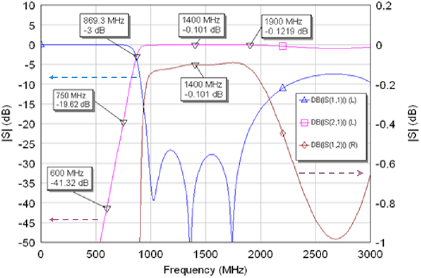
From (5), at 1.4 GHz for the two coaxial inductors with length of 1310 mil, the inductive reactance X L is 104.4 Ω; at 1.4 GHz, including circular copper inner and square brass outer conductors, the line resistance per meter, R m , is nearly 3 Ω/m; then the 1310 mil-long lines resistance R L is 0.0998 Ω. Therefore, the unload Q of these two lines, X L /R L , is 1046. Similarly, the calculated Q for the other two lines with length of 710 mil is 762.2. Comparing with traditional high Q air-core chip inductors (110 for Coilcraft 0603HP series), the short-circuit coaxial inductors will largely decrease the filter's noise. In addition to the inductors, the series capacitors are another main noise source of the filter. In this paper, high Q chip capacitors, Murata GQM series, are employed; and the Q values of GQM series are 150 in 1 GHz and 70 in 1.4 GHz, respectively (http://psearch.en.murata.com/capacitor/lineup/gqm/), which are about five times higher than that of traditional GRM series. S parameters simulation reveals that the filter's insertion loss caused by these three capacitors is 0.06 dB at 1.4 GHz. In contrast, the filter's insertion loss caused by four inductors built in this paper is only 0.018 dB at 1.4 GHz. The result of S parameter simulation for this filter is shown in Fig. 3. The 3 dB cut-off frequency is 869.3 MHz, and from 1 to 1.8 GHz, the return loss is larger than 25 dB. In passband, the insertion loss is smaller than 0.13 dB.
Filter S parameters simulation result in Microwave Office. The curves of S11 and S21 are corresponding to the left scale of Y-axis, and the curve of S12 is corresponding to the right scale of Y-axis.

III. MODULE DESCRIPTION
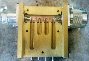
The realized filter is shown in Fig. 4. The gold-plated brass box body was milled to form four vertical elongated slots with square cross-section, and these slots act as outer conductor of coaxial cable inductors; and four pieces of copper wires were inserted into these slots to act as inner conductors. Two ends of copper wires were soldered to brass box and transmission lines on the microstrip circuit board, respectively. This circuit board with three chip capacitors soldered on was placed in the horizontal slot, and the depth of the horizontal slot was calculated accurately to fit the position of the copper wires. A male and a female low-loss N-type coaxial connector was employed as radio frequency signal input and output ports.
Filter with cover removed. N-type connectors, brass box, copper wires, Murata GQM series high Q chip capacitors, and Rogers low-loss PTFE ceramics microstrip circuit board RO3003 can be seen. The size of box with two N-type connectors uncounted is 1866 ×1598 × 1000 mil3; the circuit board is 60 mil thickness.

IV. EXPERIMENT RESULT
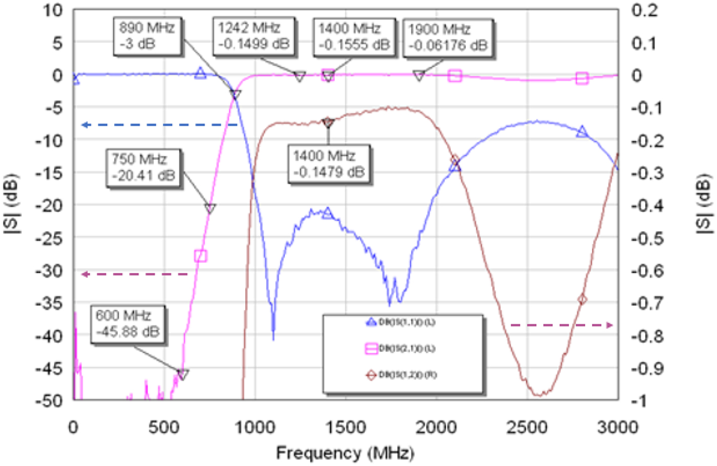
The S parameters of high-pass filter were measured by vector network analyzer PNA-X, and the results were shown in Fig. 5. From Fig. 5, the 3 dB cut-off frequency is at 890 MHz, and the upper end of passband is up to 1.9 GHz; the insertion loss in passband is lower than 0.16 dB, which is much lower than that of commercial available microstrip high-pass filters; the return loss in passband is larger than 20 dB; the stop-band rejections at 750 and 600 MHz are larger than 20 and 45 dB, respectively, which can suppress the interference of low-frequency RFI signals on the first-stage LNA of astronomical receivers effectively.
Filter S parameters measurement graph. The curves of S11 and S21 are corresponding to the left scale of Y-axis, and the curve of S12 is corresponding to the right scale of Y-axis; there are slight differences between the measured S21 and S12, which are caused by two different N-connectors (a male and a female N-connector) and slight asymmetry in components soldering.

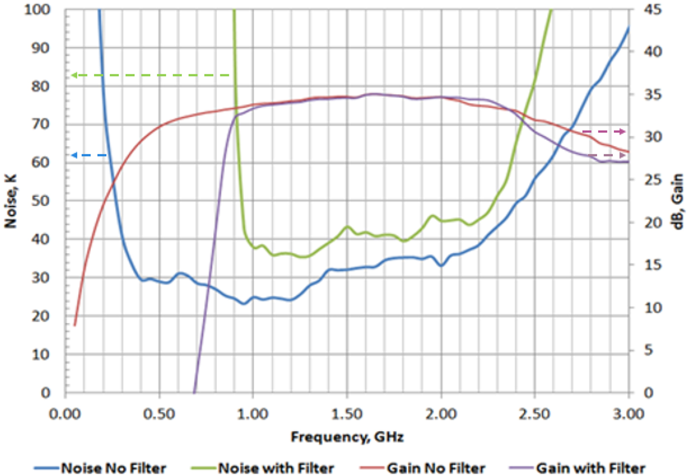
The better way to measure the noise temperature of low-noise filter is to compare the noise temperature measurement results of an LNA with and without the filter in front. A comparison measurement for Ciao LNA noise temperature and gain with and without the proposed filter in front was carried out by NFA8975A, and the results are shown in Fig. 6. It can be seen that at 1.4 GHz, the noise temperature is increased by only 8 K by the proposed filter, while this result for the best commercial low-loss high-pass filter is some dozens of Kelvin.
Measured noise of LNA with and without the proposed filter. The measurement configuration of N8975A: 201 measured points, 4 MHz of IF bandwidth and 16 times average.

V. CONCLUSIONS
We have demonstrated a very low-loss high-pass filter with novel air-core inductor design method, which can be applied to astronomical receiver frontend to keep the first-stage LNA from non-linearity distortion; and then we have given a detailed calculation analysis on noise contribution of the air-core copper wire inductors. The particular significance is the combination of very low noise, steep skirt slop, input and output power matches, and no requirement for auxiliary cooled devices.
ACKNOWLEDGEMENT
This work is partly supported by State Key Development Program for Basic Research of China (grant numbers 2012C B821806 and 2013C B837900) and the National Natural Science Foundation of China (grant number 10173015).
 Hongfei Liu received his Ph.D. degree in Microelectronics and Solid State Electronics from the State key laboratory of Integrated Optoelectronics, Department of Electronic Engineering, Jilin University, China in 2006. He is now a Senior Engineer at National Astronomical Observatories of China. He is active in the areas of the design and fabrication for radio astronomical receiver, cryogenic low-noise amplifier, low-loss filter, and data transmission optical trans-receiver.
 Sander Weinreb received his Ph.D. degree in Electrical Engineering from Massachusetts Institute of Technology of the USA in 1963. He developed the world's first digital autocorrelation spectrometer. In 1965, he became the Head of the Electronics Division and later Assistant Director of National Radio Astronomical Observatory, where he pioneered the use of low-noise cryogenically cooled solid-state amplifiers in radio astronomy. Subsequently, he worked first at Lockheed Martin Laboratories and then at the University of Massachusetts, where he developed MMIC amplifiers and other millimeter wave devices. He is now a Senior Faculty Associate at Caltech, where he has continued his work on MMIC devices. He is active in developing wideband feeds and front ends as well as investigating cost-effective designs for modest size antennas.