I. INTRODUCTION
Nowadays multi-band microstrip patch antenna (MPA) have attracted considerable attention with the rapid development of mobile communication system due to their numerous advantages like light weight, low profile, ease of fabrication, low cost, superior performance, and multi-band operation. The need for multi-band antenna has gained much attention since it is more practical for a single-antenna system to support multiple communication standard simultaneously. In recent years, the microwave research community is actively working on wide multi-band antennas in order to avoid using multiple antennas for different operating frequencies. Multi-band microstrip antenna exhibits simultaneous operation for different applications such as universal mobile telecommunications system (UMTS), long term evolution (LTE), Bluetooth, worldwide interoperability for microwave access (WiMAX), and wireless local area network (WLAN) bands [Reference Balanis1].
Generally, multi-band performance is realized by different resonating structure or resonator in the antenna. However, most of them are relatively large and/or do not provide desired bandwidths. One method of improving the bandwidth and reducing the size is to use a planar monopole antenna with slots on the patch and ground plane. However, design of a wide multi-band antenna that simultaneously operates in above bands is a tedious and challenging task. Thus, the multi-band behavior can be achieved either due to slotted patch, defected ground structure (DGS), and meandered microstrip feed since it creates additional effective inductance and capacitance thereby increasing the current path on the surface of the antenna patch [Reference Garg, Bhartia, Bahl and Ittipboon2].
Currently various types of designs have been proposed to obtain multi-band antennas. In [Reference Basaran, Olgun and Sertel3], multi-band monopole antenna has been designed using split ring resonators for WLAN and WiMAX applications. Multi-band performance has been achieved by modifying the radiating elements by introducing slots that create multi-resonant paths and hence multiple frequency bands in [Reference Mehdipour, Sebak, Trueman and Denidni4–Reference Moosazadeh and Kharkovsky7]. In above [Reference Mehdipour, Sebak, Trueman and Denidni4–Reference Moosazadeh and Kharkovsky7], a parametric study of slots of the proposed antenna is provided to obtain the required operational frequency bands for WLAN and WiMAX application. However, most of these antennas are design for either single or dual-band operation.
Narrow size planar inverted-F antenna has been designed for multi-band operation in [Reference Pazin and Leviatan8, Reference Yu and Tarng9]. However, it has a high level of cross-polarization. Proximity coupling is used to provide large bandwidth, low spurious radiation and flexibility in choosing the feedline geometry [Reference Veysi, Kamyab and Jafargholi10]. But the antenna proposed in [Reference Veysi, Kamyab and Jafargholi10] operates only in two bands.
A compact and multi-band multiple input multiple output technology (MIMO) antenna system covering global system for mobile communications (GSM) 850/900, digital communication system (DCS), personal communication system (PCS), UMTS, WLAN, and WiMAX bands has been studied in [Reference Shoaib, Shoaib, Shoaib, Xiaodong and Parini11]. The above antenna studied in [Reference Shoaib, Shoaib, Shoaib, Xiaodong and Parini11] was realized using two printed monopoles including the effect of decoupling structure on the isolation between antenna elements. A small-size printed antenna with multi-band wireless wide area network (WWAN)/LTE operation has been proposed by introducing a parasitic shorted strip and a C-shaped ground plane [Reference Lu and Guo12]. However, the width of printed circuit board in [Reference Shoaib, Shoaib, Shoaib, Xiaodong and Parini11, Reference Lu and Guo12] can further be reduced by changing the orientation of the antenna elements and decoupling structure. Proximity-coupled multi-band MPA has been proposed for different band applications in [Reference Bakariya, Dwari, Sarkar and Mandal13, Reference Bakariya, Dwari, Sarkar and Mandal14], in which the effect of slots and microstrip feed on different parts of the antenna has been studied.
A printed multi-band coplanar waveguide (CPW)-fed inverted-F antenna is presented for universal serial bus (USB) application in [Reference Soliman, Elsheakh, Abdallah and El-Hennawy15]. A CPW-fed multi-band bow-tie monopole antenna is proposed for triple-band operation in [Reference Wu and Chuang16]. Three parallel rectangular open slots etched on the ground plate of the printed antennas, are presented for multi-band applications in [Reference Li and Liu17]. In the above antenna, multi-band behavior has been achieved by using CPW fed structure as well as different shaped slots on to the patch of antenna. DGS has been used for achieving circularly polarized triple-band operation for various wireless applications in [Reference Khandelwal, Kanaujia, Dwari, Kumar and Gautam18]. Dual-band stacked circularly polarized microstrip antenna has been achieved for various wireless applications in [Reference Kumar, Kanaujia, Khandelwal and Gautam19, Reference Kumar, Kanaujia, Khandelwal and Gautam20].
In this paper, a novel design of wide multi-band antenna has been achieved using different shaped slots in the patch antenna and providing meandered microstrip fed in the ground plane. In this work, multi-band operation has been achieved firstly by using different shaped slots on the top of the patch such as circular and triangular slots. Secondly by using defected microstrip fed structure in the ground plane so as to provide desired impedance resonating structure needed for wide multi-band operation. Each operating frequency of the proposed antenna can be evaluated easily and almost independently. Proximity coupling is a technique that provides flexible feedline design in order to excite the preferred resonating modes and for the impedance matching. Till now very few wide multi-band antennas has been designed which are being fed by a proximity coupling technique.
II. ANTENNA STRUCTURE
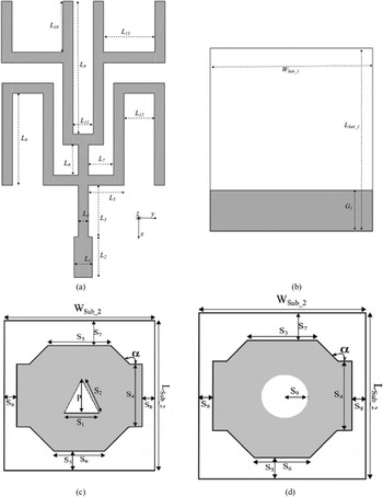
The configuration of proposed multi-band antenna is shown in Fig. 1. The geometry of meander line microstrip fed structure and slotted ground plane is shown in Figs 1(a) and 1(b), respectively. While the geometry of the proposed multi-band antenna with triangular and circular slot dimensions are shown in Figs 1(c) and 1(d), respectively. The proposed antennas are fabricated using two stacked layers each having a thickness of 0.8 mm FR-4 epoxy substrate. The relative permittivity of the substrate is 4.4 and loss tangent is 0.001. In this design, corner-truncated rectangular patch with a triangular and circular slot at its center is printed on top of the upper layer. The meandered microstrip feedline is provided on top of the lower substrate layer to obtain proximity coupling. On the other side a semi ground plane is used. Meandered line is working as a monopole antenna and shows resonance at 2.35 GHz. Further, fed line is stacked with shaped patch antenna and proposed structure shows dual-band characteristics. To achieve triple-band characteristics triangular and circular shaped slots are embedded on the patch. Length of the upper substrate layer is slightly smaller than the lower layer in order to keep a provision for connection of inner conductor of an sub-miniature A connector (SMA) connector to the microstrip fed. Commercial software Ansoft HFSS 14 is used to perform the simulations.
Schematic of the proposed antenna: (a) feed lines, (b) ground plane, (c) patch with triangular slot, and (d) patch with circular slot.

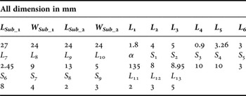
The simulations are carried out to investigate the effect of different dimensions of the slot-loaded antenna as well as different dimension of meander microstrip feedline to obtain desired multi-band operation. From the result it can be seen that good input impedance matching for all of the UMTS, LTE, Bluetooth, WiMAX, and WLAN bands can be obtained by tuning different dimensions of the corner-truncated triangular and circular slot-loaded patch as well as different dimension of meander microstrip line. The optimal antenna parameters as obtained are given in Table 1. Fabricated structure is connected with a 50 Ω SMA connector.
Optimized parametric values of proposed antenna.

III. DESIGN CONSIDERATION AND RESULT ANALYSIS
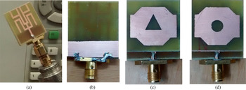
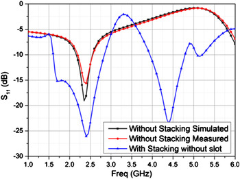
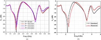
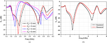
All the proposed antennas are fabricated by standard photolithography process on the substrate FR-4 epoxy having permittivity and loss tangent of 4.4 and 0.001, respectively. All the substrates are used with height of 1.6 mm. Electrical characteristics of the fabricated antennas are measured by Agilent PNA-L series Network Analyzer (see Fig. 2). SMA connector is used for feeding the structure. Antenna without stacking is showing a resonance at 2.35 GHz. The return loss level of the meandered fed with semi-ground plane (without stacking) is about 19.1 dB at 2.35 GHz as shown in Fig. 3. The proposed feed is stacked with shaped patch and stacked structure starts to show dual-band characteristics. Further, the proposed patch structure with triangular shaped slot is stacked to feed and it shows triple-band characteristics. The proposed antenna with triangular shaped slot shows three resonances with minimum return loss level of 44.44, 23.91, and 15.85 dB at 2.2, 4.45, and 5.3 GHz, respectively. The S 11 characteristics of Ant2 are shown in Fig. 4. Ant2 has impedance bandwidth of 45.9, 19.23, and 15.67%, respectively. Figure 4(a) shows the return loss characteristics of Ant2 for different values of P of triangular slot. For P = 8 mm better results are obtained and Ant2 is fabricated for the same value. For P = 9.5 mm almost same results are observed but comparably higher loss is achieved for the first band; thus we take 8 mm value for fabrication purpose. With the lower value of P the third band shows higher losses. Further, triangular slot is replaced by circular slot (Ant3) and impedance bandwidth at the first and second bands is enhanced. Ant3 resonates with the return loss level 36.13, 22.47, and 14.95 dB at 2.2, 4.42, and 5.38 GHz, respectively. Ant3 shows impedance bandwidth of 50.24, 33.21, and 13.43% respectively. Bandwidth at the first and second resonances is enhanced by 4.34 and 13.98%, respectively. The S 11 characteristics of Ant3 are depicted in Fig. 5. Return loss characteristics of Ant3 for different values of radius S 9 of circular slot are shown in Fig. 5(a) and it is observed that the proposed antenna shows the best triple-band characteristics for S 9 = 3 mm. With the increase of S 9 higher bands are merged and start to show wide band. On comparison of Figs 3–5; it is cleared that only feed (without stacking) shows single-band characteristics, by stacking with the proposed shaped patch without any slot antenna starts to show dual-band characteristics, further triple-band characteristics are achieved by embedding triangular and circular slots.
Prototypes of fabricated antennas: (a) feed lines, (b) ground plane, (c) patch with triangular slot, and (d) patch with circular slot.

S 11 characteristics with frequency of meandered fed with semi-ground plane and without stacking and with stacking without slot.

S 11 characteristics with frequency of meandered fed with semi-ground plane and stacked with triangular slot; (a) For different values of P, (b) For P = 8 mm.

S 11 characteristics with frequency of meandered fed with semi-ground plane and stacked with circular slot; (a) For different radius of circular slot, (b) For S 9 = 3 mm.

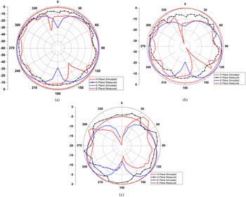
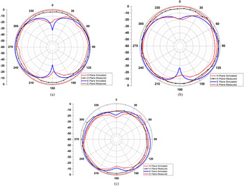
Figure 6 shows the gain characteristics of triangular slot-loaded stacked patch antenna. Ant2 shows an omnidirectional pattern in the H-plane (xz-plane) at first two resonances. Ant2 has almost unity gain in the xz-plane at first two resonances and negative gain in an orthogonal plane; which is a merit of proper omnidirectional pattern. Ant2 shows about −2 dBi gain at 90° and 270° at second resonance 4.45 GHz. At 5.3 GHz; Ant2 is not showing proper omnidirectional pattern and gain is below unity from 90° to 270°.
Gain characteristics of Ant2 (with triangular slot) at: (a) 2.2 GHz, (b) 4.45 GHz, and (c) 5.3 GHz.

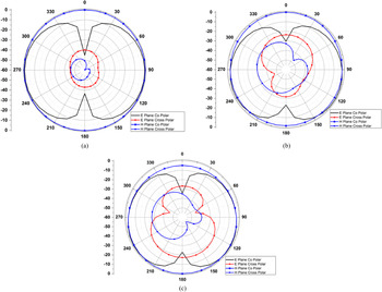
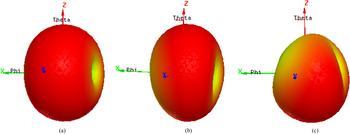
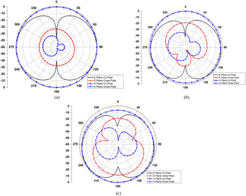
The normalized co-polar and cross-polar radiation characteristics of Ant2 are shown in Fig. 7. The minimum values of the cross-polarization level of Ant2 in the E-plane are −40, −25, and −20 dB at 2.2, 4.45, and 5.3 GHz, respectively. In the H-plane; the minimum values of cross-polarization of Ant2 are −40, −30, and −28 dB. Figure 8 shows the three-dimensional (3D) radiation patterns of Ant2 at all three working frequencies. From Fig. 8 it is very clear that Ant2 has an omnidirection pattern in the xz-plane at the first two frequencies.
Normalized radiation pattern of Ant2 (with triangular slot) at: (a) 2.2 GHz, (b) 4.45 GHz, and (c) 5.3 GHz.

3D radiation pattern of Ant2 (with triangular slot) at: (a) 2.2 GHz, (b) 4.45 GHz, and (c) 5.3 GHz.

Figure 9 shows the gain characteristics of circular slot-loaded stacked patch antenna. Ant3 shows omnidirectional pattern in H-plane (xz-plane) at first two resonances. Ant3 shows good radiation characteristics as an omnidirectional antenna; it has almost unity gain in the xz-plane at the first two resonances and negative gain in the orthogonal plane. At 5.4 GHz; Ant3 is not showing a proper omnidirectional pattern around 0°.
Gain characteristics of Ant3 (with circular slot) at: (a) 2.25 GHz, (b) 4.4 GHz, and (c) 5.4 GHz.

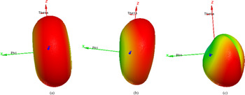
The normalized co-polar and cross-polar radiation characteristics of Ant3 are shown in Fig. 10. The minimum values of the cross-polarization level of Ant3 in the E-plane are −42, −29, and −10 dB at 2.25, 4.4, and 5.4 GHz, respectively. In the H-plane; the minimum values of cross-polarization of Ant3 are −50, −40, and −35 dB. The cross-polarization level is more suppressed by using circular slot except at 5.4 GHz in the E-plane. Figure 11 shows the 3D radiation patterns of Ant3 at all the three working frequencies. From Fig. 11 it is very clear that Ant3 has an omnidirection pattern in the xz-plane at the first two frequencies.
Normalized radiation pattern of Ant3 (with circular slot) at: (a) 2.25 GHz, (b) 4.4 GHz, and (c) 5.4 GHz.

3D radiation pattern of Ant3 (with circular slot) at: (a) 2.25 GHz, (b) 4.4 GHz, and (c) 5.4 GHz.

IV. CONCLUSION
A novel design of wide multi-band antenna feed with proximity coupled meandered microstrip line is proposed for various wireless applications such as Bluetooth, WiMAX, and WLAN bands. In this design, a corner-truncated rectangular patch with triangular and circular slots is proposed for wide multi-standard operation due to the slotted ground plane so as to provide a desired impedance resonating structure. Both the antenna shows triple resonance at frequencies 2.2, 4.45, and 5.3 GHz having excellent bandwidth. By using the circular slot in place of triangular; bandwidth of the first and second bands is improved by 4.34 and 13.98%, respectively. Each operating frequency of the proposed antenna can be evaluated easily and almost independently. The antenna shows stable gain and omnidirectional radiation characteristics for entire triple-band operation. Also the antenna shows small cross-polarization characteristics. The circular slot provides a larger impedance bandwidth in comparison with triangular slot; however, it leads to a larger level of cross-polarization than the antenna with the triangular slot. The simulated and measured results are shown to have good agreements.
 Jaishanker Prasad Keshari was born in Ballia (Uttar Pradesh), India. He received his B.Tech. (in Electronics and Communication Engineering) degree from Uttar Pradesh Technical University, Lucknow, India and M. Tech. (in Instrumentation and Control Engineering) degree with gold medal from Sant Longowal Institute of Engineering and Technology, Punjab, India, in 2004 and 2007, respectively. He is currently working toward his Ph.D. degree at Sharada University, Greater Noida, India. He has worked as an Assistant Professor at Electronics and Communication Engineering Department of Noida Institute of Engineering and Technology College, Greater Noida, India. Currently, he is working as an Assistant Professor at Instrumentation and Control Engineering of Galgotia College of Engineering and Technology, Greater Noida, India. His research interest includes microstrip patch antenna and waveguide structures for gyro-traveling-wave tubes. He has a number of research papers in peer-reviewed journals and conference proceedings. Mr. Keshari received the best teacher award for his academic excellence in the year 2008–2014 at Noida Institute of Engineering and Technology, as well in Galgotia College of Engineering and Technology Greater Noida, India.
 Binod Kumar Kanaujia is currently working as a Professor in the Department of Electronics & Communication Engineering in Ambedkar Institute of Advanced Communication Technologies & Research (formerly Ambedkar Institute of Technology), Geeta Colony, Delhi. Dr. Kanaujia joined this institute as an Assistant Professor in 2008 through selection by Union Public Service Commission, New Delhi, India and served on various key portfolios, i.e. Head of Department, In-charge of Central Library, Head of Office, etc. Before joining this institute he had served in the M.J.P. Rohilkhand University, Bareilly, India as a Reader in the Department of Electronics & Communication Engineering and also as the Head of the Department. He has been an active member of Academic Council and Executive Council of the M.J.P. Rohilkhand University and played a vital role in academic reforms. Prior, to his career in academics, Dr. Kanaujia had worked as an Executive Engineer in the R&D division of M/s UPTRON India Ltd. Dr. Kanaujia had completed his B.Tech. in Electronics Engineering from KNIT Sultanpur, India, in 1994. He did his M.Tech. and Ph.D. in 1998 and 2004; respectively, from the Department of Electronics Engineering, Indian Institute of Technology Banaras Hindu University, Varanasi, India. He has been awarded Junior Research Fellowship by UGC Delhi in the year 2001–2002 for his outstanding work in the electronics field. He has keen research interest in design and modeling of microstrip antenna, dielectric resonator antenna, left-handed metamaterial microstrip antenna, shorted microstrip antenna, ultrawideband antennas, reconfigurable, and circular polarized antenna for wireless communication. He has been credited to publish more than 105 research papers with more than 200 citations with h-index of ten in peer-reviewed journals and conferences. He had supervised 45 M.Tech. and three Ph.D. research scholars in the field of Microwave Engineering. He is a reviewer of several journals of international repute, i.e. IET Microwaves, Antennas & Propagation, IEEE Antennas and Wireless Propagation Letters, Wireless Personal Communications, Journal of Electromagnetic Wave and Application, Indian Journal of Radio and Space Physics, IETE Technical Review, International Journal of Electronics, International Journal of Engineering Science, IEEE Transactions on Antennas and Propagation, AEU-International Journal of Electronics and Communication, International Journal of Microwave and Wireless Technologies, etc. Dr. Kanaujia had successfully executed four research projects sponsored by several agencies of Government of India, i.e. DRDO, DST, AICTE, and ISRO. He is also a member of several academic and professional bodies, i.e. IEEE, Institution of Engineers (India), Indian Society for Technical Education, and The Institute of Electronics and Telecommunication Engineers of India.
 Mukesh Kumar Khandelwal received his B.Tech. degree in Electronics & Communication Engineering in 2010, M.Tech. degree in Digital Communication in 2012 from GGSIP University, Delhi, India and Ph.D. degree in Electronics Engineering from Indian School of Mines, Dhanbad, India, in 2015. Dr. Khandelwal has published thirteen research papers in referred International Journals and Conferences (11-SCI Journals, 02-IEEE International Conferences). His current research interests focus on microstrip antennas, defected ground structure, and microwave components.
 Pritam Singh Bakariya was born in Khandwa, Madhya Pradesh, India, in 1985. He received his B.E. degree in Electronics and Communication Engineering from Ujjain Engineering College, Ujjain, India, in the year of 2007 and his M. Tech. degree in Optical Communication Engineering from Shri Govindram Seksaria Institute of Technology and Science, Indore, India, in 2009 and Ph.D. degree in RF and Microwave Engineering from the Department of Electronics Engineering, Indian School of Mines, Dhanbad, India, in 2016. Presently he is working as an Assistant Professor in the Department of Electronics and Communication Engineering, SR Engineering College, Warangal, India. He has published several research papers in referred International Journals. His recent research interest activities have focused on the Antennas, RF planar circuits, and Computational Electromagnetics.
 Professor R.M. Mehra holds Ph.D. degree in Physics from the University of Delhi, Delhi, India. He superannuated from the University of Delhi in January 2010 and joined as an Emeritus Professor at Sharda University. At the University of Delhi, he was engaged in teaching, research, and administration. He has been post-doctoral research fellow of Japan Society for Promotion of Sciences (JSPS, Japan). Presently he is the Dean Research, Sharda University; HoD, Department of Electronics and Communication Engineering; and Advisor, Learning Resource Center. He has already supervised 42 Ph.D. research scholars for award of doctoral degree. He has published 172 research papers in SCI journals with more than 1770 citations with h-index 23 (SCOPUS). He is presently supervising six research scholars for Ph.D. degree at Sharda University. His area of interest is electronic materials and devices. He has written various review articles, mainly on Amorphous Semiconductors, which have been widely accepted and recognized by international research community. Currently, he is Chief Editor of Invertis Journal of Renewable Energy and member of Advisory Editorial Board of Materials Science, Poland. He is reviewer for research papers of several important international journals such as, Applied Physics Letters (AIP, USA), Journal of Applied Physics (AIP, USA), Journal of Non-crystalline Solids (Elsevier Science), Thin Solid Films (Elsevier Science), Journal of Applied Polymer Science (Wiley Inter Science, USA), Solar Energy Materials and Solar Cells (SOLMAT), Applied Surface Science (Elsevier Science), and Polymer Engineering Science. Professor Mehra has executed more than 16 research projects sponsored by national (DRDO, UGC, DST, CSIR, MNRE, and IUAC) and international (NSF, USA & JSPS, Japan) agencies. He is a member of several academic and professional bodies and has chaired Semiconductor Society (India).