INTRODUCTION
In recent years, the interest in table top laser based hard X-ray sources for laboratory based applications has increased dramatically (Dorchies et al., Reference Dorchies, Harmand, Descamps, Fourment, Hulin, Petit, Peyrusse and Santos2008; Gizzi, Reference Gizzi, Yamanouchi, Giulietti and Ledingham2010; Guo, Reference Guo2009; Hatanaka et al., Reference Hatanaka, Ono and Fukumura2008; Hou et al., Reference Hou, Easter, Mordovanakis, Krushelnick and Nees2008; Kugland et al., Reference Kugland, Constantin, Neumayer, Chung, Collette, Dewald, Froula, Glenzer, Kemp, Kritcher, Ross and Niemann2008; Lee et al., Reference Lee, Jiang, Rose-Petruck and Benesch2005; Silies et al., Reference Silies, Witte, Linden, Kutzner, Uschmann, Förster and Zacharias2009; Tarasevitch et al., Reference Tarasevitch, Gibbon, Mašek, Teubner, Lu, Nicoul, Shymanovich, Zhou, Sokolowski-Tinten and Linde2009; Zamponi et al., Reference Zamponi, Ansari, Korff Schmising, Rothhardt, Zhavoronkov, Woerner, Elsaesser, Bargheer, Trobitzsch-Ryll and Haschke2009; Fullagar et al., Reference Fullagar, Uhlig, Gador, Kinnunen, Maasilta, Wahlström and Sundström2010; Chen et al., Reference Chen, Kando, Xu, Li, Koga, Chen, Xu, Yuan, Dong, Sheng, Bulanov, Kato, Zhang and Tajima2008, Reference Chen, Liu, Wang, Kando, Mao, Zhang, Ma, Li, Bulanov, Tajima, Kato, Sheng, Wei and Zhang2010; Mangles et al., Reference Mangles, Walton, Najmudin, Dangor, Krushelnick, Malka, Manclossi, Lopes, Carias, Mendes and Dorchies2006). Temporal multi-pulse regimes have been assessed in attempts to increase X-ray yields (Ahn et al., Reference Ahn, Nakano, Nishikawa and Uesugi1996; Anand et al., Reference Anand, Kahaly, Kumar, Krishnamurthy, Sandhu and Gibbon2006; Hatanaka et al., Reference Hatanaka, Ono and Fukumura2008). Several publications report collimated electron beams with narrow energy distributions generated with femtosecond lasers in the several mJ class, using solid or micro droplet targets in high vacuum (Anand et al., Reference Anand, Gibbon and Krishnamurthy2007; Bastiani et al., Reference Bastiani, Rousse, Geindre, Audebert, Quoix, Hamoniaux, Antonetti and Gauthier1997; Li et al., Reference Li, Daido, Fukumi, Sagisaka, Ogura, Nishiuchi, Orimo, Hayashi, Mori, Kado, Bulanov, Esirkepov, Oishi, Nayuki, Fujii, Nemoto, Nakamura and Noda2006; Ruhl et al., Reference Ruhl, Sentoku, Mima, Tanaka and Kodama1999; Zhang et al., Reference Zhang, Li, Sheng, Wei, Dong and Lu2005; Nakano et al., Reference Nakano, Nishikawa, Ahn and Uesugi1996). Their use has been proposed in electron scattering experiments and for accelerator injection (Hu et al., Reference Hu, Lei, Wang, Wang, Huang, Wang, Xu, Liu, Yu, Shen, Li and Xu2010; Mordovanakis et al., Reference Mordovanakis, Masson-Laborde, Easter, Popov, Hou, Mourou, Rozmus, Haines, Nees and Krushelnick2010; Fullagar et al., Reference Fullagar, Uhlig, Walczak, Canton, Wahlström and Sundström2007a; Centurion et al., Reference Centurion, Reckenthaeler, Trushin, Krausz and Fill2008; Reckenthaeler et al., Reference Reckenthaeler, Centurion, Fuss, Trushin, Krausz and Fill2009; Centurion et al., Reference Centurion, Reckenthaeler, Fuss, Trushin, Apolonski, Krausz and Fill2009). This report surveys our work on laser plasma generated electron beams based on water jet targets performed at the Lund Laser Center's terawatt laser system (Svanberg et al., Reference Svanberg, Larsson, Persson and Wahlström1994; Mangles et al., Reference Mangles, Genoud, Kneip, Burza, Cassou, Cros, Dover, Kamperidis, Najmudin, Persson, Schreiber, Wojda and Wahlström2009). The use of a water jet target, under helium atmosphere at ambient pressure or water aspirator vacuum, is motivated by foreseeable chemical ultrafast X-ray applications (Fullagar et al., Reference Fullagar, Harbst, Canton, Uhlig, Walczak, Wahlström and Sundström2007b, Reference Fullagar, Uhlig, Walczak, Canton and Sundstrom2008). The work described herein strongly supports long-standing evidence (Max, Reference Max1980) that the existence of a pre-plasma — formed by the first pulse of a temporal multi-pulse structure — is critical for the generation of electron beams by subsequent laser pulses, and that these must be p-polarized. Indeed the appearance of electron emission has been symptomatic for occasional problems with the laser system. In this work, two collinear orthogonally polarized pulses of comparable energy are arranged, and focused to strike a circular cross section water jet at a predetermined angle, usually at grazing incidence. The constraint of equal laser energy in both pulses was used merely to simplify the exploration of laser parameter space. However, electron beams were identified at different intensity ratios too. In the context of laser generated X-rays from condensed matter targets, the electron beams must be recognized in interests of radiation safety, optimization of X-ray emission from the intended target, and elimination of secondary emissions. Controlling their directionality, angular spread, charge and energy is of critical interest for subsequent applications. At the same time, exerting the necessary control has been a major obstacle in the characterizations described here. Laser-plasma interaction is a complex and extremely active field of research whose theoretical and numerical treatments lie outside the scope of this work, which aims at a symptomatic description.
EXPERIMENTAL SETUP
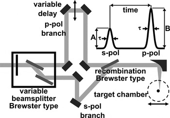
For the results presented, we used about 800 nm parasitic pulses from the 10 Hz multi-terawatt laser at the Lund Laser Centre with typically about 40 mJ pulse energy and chirp controlled durations of about 46 fs up to several picoseconds. These typically have excellent temporal contrast ratio as described elsewhere (Lindau, Reference Lindau2007). We have also observed electron beams with a 3 mJ 1 kHz system with lower temporal contrast, results of which will be discussed in the remark section. For the deliberate generation of high temporal contrast pre-pulses, the arrangement sketched in Figure 1 was used.
A 3 ns delay stage varies the relative timing between two variably split beams of opposite linear polarization, the power division of which is controlled using a 1/2-wave plate. After their recombination using a Brewster type mirror the beam is tightly focused by a 90° off axis parabolic metallic mirror onto the target. The target is moved relative to the focus and consists of a ~3 ms−1 water jet in laminar flow conditions.

In this arrangement, the p-polarized pulse passes through two Brewster type polarizer's. Laser chirp scans (of the inter-grating spacing in the optical compressor) have been routinely performed throughout our experimental campaigns to find the shortest pulse duration for the p-polarized pulse at the target position, thus compensating for group velocity dispersion in this and other glass downstream from the compressor (e.g., target chamber windows). The compressor settings of the shortest pulse duration is determined by using optical autocorrelator traces or by the generation of white light in air at low laser energy per pulse and by the form of the resulting X-ray curves (see Fig. 4a). In the configuration used, the s-polarized pulse is not compensated in the same way, and thus obtains a slightly different chirp and pulse duration. However, this and associated work (Fullagar et al., Reference Fullagar, Harbst, Canton, Uhlig, Walczak, Wahlström and Sundström2007b) show that the s-polarized pre-pulse does not itself lead to any significant hard radiation (X-rays or electrons) — its function is merely to generate a plume of expanding matter at the target surface. In this role, optimum group velocity dispersion compensation of the s-polarized pulse is not critical. Inter-pulse delays of up to ±1.5 ns could be realized. The two pulses are tightly focused by the same off-axis parabolic mirror. Laser intensity at the target was varied in the region 1015–1018 Wcm−2. The water jet target has a circular cross section with about 180 µm diameter and is directed vertically downwards in a helium atmosphere at atmospheric pressure, alternatively drawn into a vacuum close to the vapor pressure of water. Stable vacuum operation of the water jet is achieved by degassing the water and by drawing it into the chamber by use of a water aspirator pump, whose vacuum is automatically limited to water's vapor pressure at room temperature. In addition to degassing, a stable jet requires that the water is cooled a few degrees prior to its introduction to the chamber. The necessity of doing so confirms that the chamber pressure is close to the room temperature vapor pressure of water (about 23 mbar at 20°C).
The primary radiation detector was a 512 × 512 pixel direct detection charge-coupled device (CCD)(Princeton Instruments SX-TE/CCD-512TKB/D), whose characterization and operation is described in a previous paper (Fullagar et al., Reference Fullagar, Uhlig, Walczak, Canton and Sundstrom2008). A particularly useful mode of operation for these electron beam studies is the vertically (hardware) binned, laser-synchronous mode. This allows data capture at the laser repetition rate while preserving one axis of spatial information. Much of the data presented below integrates this remaining axis, so that individual data points show the integrated frame intensity corresponding to individual laser shots. This permits straightforward graphical presentation of scans of the many variables in the laser and experimental parameter space (jet position, laser chirp, inter-pulse delay, intensity ratio, etc). At the same time, the additional data dimension is retrievable from the original data. For charge measurements, we observed the induction caused by the electron beams through a calibrated ferrite toroid. Wide-angle beam divergence and its real time shot-to-shot stability was externally observed as fluorescence generated in Kodak Lanex Gd2O2S:Tb fluorescent screens lining the inside of transparent vacuum cylinders, in contact with 110 μm of aluminum on the target side to filter target-generated X-radiation softer than about 7 keV and scattered laser light (Glinec et al., Reference Glinec, Faure, Pukhov, Kiselev, Gordienko, Mercier and Malka2005). Magnetic deflection of the beams after passage through a collimating aperture is observable on the screen and confirms the charge polarity, electron energy, and the absence of detectable co-propagating X-ray beams such as potential betatron radiation (Rousse et al., Reference Rousse, Phuoc and Albert2007). When operating in the single pulse mode, X-ray emission is isotropic, with insufficient energy to substantially penetrate the aluminum filter. Thus, and in practice, the fluorescent screen is not perceptibly illuminated during X-ray generation as described in our account of this X-ray source (Fullagar et al., Reference Fullagar, Harbst, Canton, Uhlig, Walczak, Wahlström and Sundström2007b). Details about the respective detectors and their choice are given below.
OBSERVATIONS
Scanning the delay between the two orthogonal polarized pulses reveals dramatically different behavior on either side of simultaneous arrival. If the s-polarized pulse arrives first, it generates no substantial X-rays from the undisturbed target (Fullagar et al., Reference Fullagar, Harbst, Canton, Uhlig, Walczak, Wahlström and Sundström2007b), but nevertheless interacts with the surface leading to formation of a plume that rapidly expands away from the surface. The subsequent p-polarized pulse enters the density gradients presented by this plume, and interacts with it. It is this situation in which high energy electron emissions are observed. If, on the other hand, the p-polarized pulse arrives first, it can stably generate hard X-rays from the target. In this case, the subsequent s-polarized beam does not lead to hard X-rays or hot electrons that we have been able to observe.
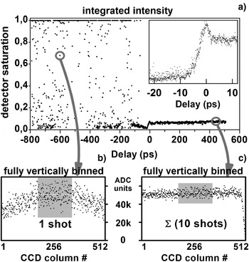
This behavior is shown in Figure 2a where the relative delay was scanned several hundred picoseconds on either side of simultaneous pulse arrival. The electron beams that form the subject of this paper, and whose identity is confirmed later, appear as high intensity data points at negative delay times.
(a) shows the integrated frame signal of the laser synchronous X-ray CCD, vs. delay between s- and p-polarized laser pulses. The inset shows the transition to stable X-ray production when the p-pulse precedes the s-pulse (positive delay). Destruction of conditions for efficient X-ray generation occurs within 5 ps both in helium (main scan) and in vacuum (inset), for which the general behaviour is similar. (b) expands the indicated non-saturating electron beam shot into the corresponding CCD columns (see text). (c) sums 10 consecutive shots during stable X-ray production in order to give a result with comparable average intensity in the shaded CCD columns. Substantially higher shot noise is evident in (b) than in (c), illustrating the higher energy of the radiation quanta in (b) (see text).

In these measurements, radiation passed through about 5 cm of helium gas at atmospheric pressure, about 50 μm of Beryllium, about 7 mm of air, and about 500 μm of Beryllium, before partial or complete registry at different depths in about 15 μm thick Silicon CCD, which is described elsewhere (Fullagar et al., Reference Fullagar, Uhlig, Walczak, Canton and Sundstrom2008). The X-ray photon energy of about 3–10 keV is unaltered by transit through matter, whereas individual electrons lose energy, so that the energy of detected electron quanta deposited in the thin Silicon detection layers is a fraction (F) of the electrons' original energy. We can anticipate that F will be rather small for electrons with energies on the order of 100 keV, for which we might expect F = 0.1 – 0.5 (Berger et al., Reference Berger, Coursey, Zucker and Chang1998). Nevertheless, the electron generated charge clouds often saturate the CCD preamplifier, which was at its lowest gain setting for this measurement. This and other comparable scans indicate that inter-pulse delays of 15 ps — 1.5 ns produce electron emissions in the direction of the CCD camera, here mounted in the horizontal plane at 90° from the incoming laser beam. The fixed and small angle of detection and generally erratic nature of the intensity spikes suggest that even shorter inter-pulse delays may be effective for their generation. The inset of Figure 2a shows the steep drop in X-ray production that occurs on a timescale of ~5 ps when the s-polarized pulse precedes the p-polarized pulse. It indicates the timescale of disruption of the sharp plasma gradient conditions that are a prerequisite for stable X-ray generation. The X-ray pulse itself is likely shorter than this (Fullagar et al., Reference Fullagar, Harbst, Canton, Uhlig, Walczak, Wahlström and Sundström2007b).
Figures 2b and 2c show the data retained within individual points of Figure 2a when using the synchronously binned CCD procedure and can be used to estimate the electron energy. Noise is observable in the intensity distribution along the horizontal axis of the CCD for each laser shot. Its interpretation as quantum shot noise indicates that the energies deposited by detected electron radiation quanta are substantially higher than for typically 3–10 keV X-rays. Thus, for a particular non-saturating electron beam shot, we observe a standard deviation of σ = 7500 analog to digital converter units (ADCU) in Figure 2b, with average intensity I = ~52000 ADCU/column. In the region of stable X-ray production, the summation of 10 shots in Figure 2c leads to a comparable intensity, but with σ = 2900 ADCU. For the electrons, Poisson statistics indicates σ/I = N −1/2, implying an average of N =~48 events/column. The observed average intensity is I = N·E·F/k, where E is the unknown radiation quantum energy, F was defined previously, and k =~40 eV/ADCU is the calibration factor (gain setting) of the CCD in the experiment. Rearrangement gives E = (I·k/N)/F =~43000/F electron-volts. Thus, about 43 keV is a lower bound for the original electron energy (corresponding to F = 1), however, based on our anticipations concerning F in the previous paragraph, the measurement implies electron energies in the 100s of keV range. A better estimate by this approach would require quantitative assessment of F (bearing in mind that electrons may not be monoenergetic) and treatment of the scattering and secondary radiations caused by such energetic electrons (primarily bremsstrahlung and X-ray fluorescence). The steep intensity drop above CCD column 500 in Figure 2c is due to shielding by a lead block. The smearing of this edge in Figure 2b shows the property of the electron beams to scatter on transit through air and the CCD's beryllium window. Similar scattering can also be seen in our earlier magnetic deflection data (Fullagar et al., Reference Fullagar, Uhlig, Walczak, Canton and Sundstrom2008).
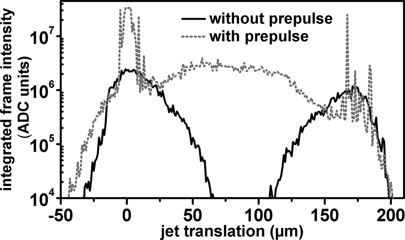
Scans of the jet through the laser focus are shown in Figure 3, with and without the prepulse. In these scans, as in all data obtained using the CCD, the position of the jet was first adjusted to give grazing laser incidence on the side of the water jet closer to the CCD. Single p-polarized pulses were then used to optimize the observable X-ray signal in real time. In Figure 3, after establishing the optimum position, the jet was translated away from the CCD, before commencing data recording and manually scanning it at a steady rate towards the CCD, all the way through the laser focus. In the single pulse mode, two radiation peaks are invariably observed, corresponding to focusing on the near and far side of the jet. The second peak is somewhat smaller because the essentially isotropic, few keV broadband X-ray radiation is attenuated by its passage through the jet. Figure 3 also suggests the approach by which we can reliably generate electron emission; by first optimizing the stable X-ray emissions in a grazing incidence geometry on the CCD side of the jet with a single p-polarized pulse, then admitting a prepulse. The shape of the trace observed during the scan then changes dramatically. Erratic sharp peaks at about 0 µm and about 170 µm on the abscissa correspond to electron emission normal to the target surface for grazing laser-target interaction geometry. Erratic electron beams can also be observed at other, apparently arbitrary incidence angles, where their appearance can be optimized by translating the jet downstream in the converging laser beam, thus returning the water jet surface to the laser focus. This adjustment was not made in Figure 3, where we note instead that the electron beams appear capable of traversing the water jet (occasional flashes at about 170 µm on the abscissa; minor contributions from secondary radiations may also contribute). When striking the center of the water jet with the double pulse, radiations are again observable, in contrast to the single pulse measurement. If the simple double-peak X-ray behavior is not observed when a single ultrafast laser pulse is used, then experience has shown to expect impaired laser temporal contrast. Indeed, changes of this double-peak X-ray behavior, often accompanied by electron beams, have proven to be convenient indicators when troubleshooting occasional temporal problems of the laser systems.
Radiation observed using the X-ray CCD when scanning the water jet through the laser focus. The black trace uses a single p-polarized laser pulse, producing stable X-ray emission at grazing incidence on either side of the jet. The grey dotted trace adds an s-polarized prepulse, here showing erratic electron emissions at grazing incidence on either side of the jet. In addition, X-ray emission is observed at normal incidence (see text).
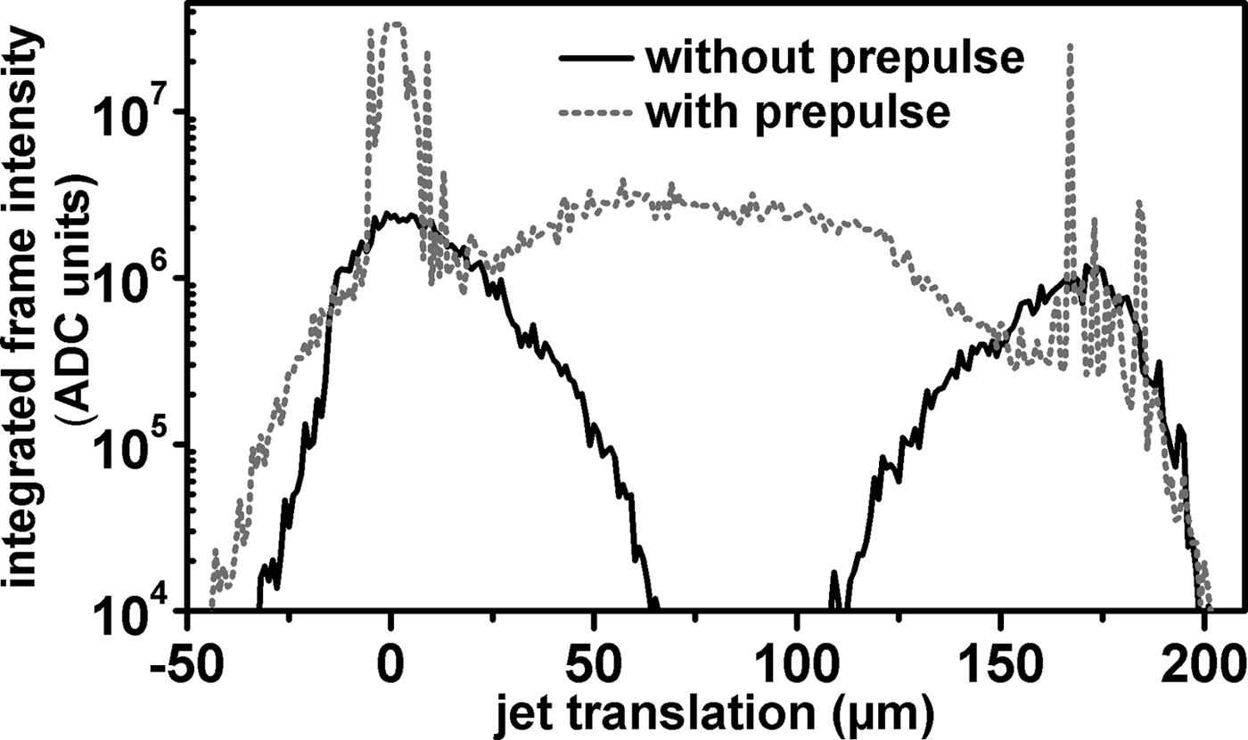
When striking the water jet at normal incidence in Figure 3, the circular cross section of the water jet surface lies slightly before the laser waist. In this geometry, the concepts of s- and p-polarized incidence cease to have meaning, although it is conceivable that the direction of emissions depends on the polarization (i.e., not isotropic), and the practical equivalence of the two pulses remains to be confirmed by delay scans such as in Figure 2, perhaps with appropriate equalization of the chirp in both pulses. In Figure 3, this normal incidence, double pulse arrangement appears capable of somewhat increasing the X-ray emission from the source over the single pulse grazing incidence geometry, which might be of interest in future applications. The observed radiation (in the abscissa range about 50–130 μm in Fig. 3) requires the second pulse for its generation, and shows quantum shot noise comparable to the X-rays generated by the single p-pulse in grazing incidence, noting also its relatively stable behavior and moderate average intensity in this scan.
Here the situation appears to be that of coronal hole punching and associated ponderomotive electron acceleration to the critical density, as proposed for fast ignition schemes in inertial confinement fusion (Tabak et al., Reference Tabak, Hammer, Glinsky, Kruer, Wilks, Woodworth, Campbell, Perry and Mason1994; Mulser & Bauer, Reference Mulser and Bauer2004, Reference Mulser, Bauer, Höhler, Fujimori, Kühn, Müller, Steiner, Trümper and Wölfle2010). However, at this stage, our investigations of this double pulse, normal incidence geometry have not been taken further, and so contain the possibility of secondary radiations arising from the target chamber. Shadow images, spectrally resolved data, and temporally resolved X-ray streak camera measurements could resolve these questions in future experiments.
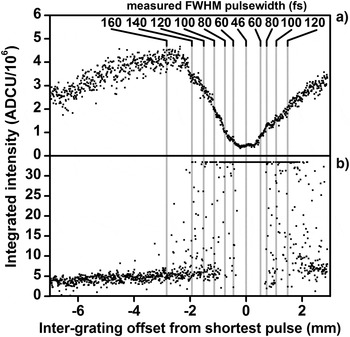
Figure 4 shows the X-ray production under helium (Fig. 4a) and electron beam production under vacuum (Fig. 4b) as functions of laser chirp on either side of its shortest value, as indicated by an optical autocorrelator. Note the change of vertical scale in the panels for the radiation data and frequent CCD saturation by the electron beams. For X-rays, the maximum radiation yield corresponds to a laser pulse duration of about 150–200 fs (Fullagar et al., Reference Fullagar, Harbst, Canton, Uhlig, Walczak, Wahlström and Sundström2007b). The different behavior of the X-ray and electron emission with respect to laser pulse duration indicates different mechanisms for their generation. Both kinds of radiation emission appear symmetrical about the shortest pulse duration (about 46 fs), implying that chirp polarity is not a critical aspect of either generation process. This symmetric chirp behavior and optimal reliability at shortest pulse durations implies that pulse intensity is essential for electron beam formation. To ensure shot-to-shot reproducibility of the preplasma plume structure and associated directional instabilities of the electron beams, excellent pointing stability is desirable, as the following measurements show. Instability in the direction of the emitted electron beams is a contributing aspect of the erratic electron intensity observations in Figures 2, 3, and 4.
(a) shows a scan of the X-ray yield observed by the CCD vs. inter-grating distance (chirp). The inset numbers give the approximate pulse duration in femtoseconds with the shortest pulse corresponding to about 46 fs. The X-rays were generated using a high contrast ratio single p-polarized pulse. In (b) a prepulse is added, leading to production of fast electrons. Note the change of intensity scale, including frequent CCD saturation by the electrons, and apparent symmetry of radiation yield with regard to sign of the chirp.

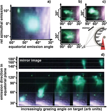
In Figure 5, the lead target chamber and CCD are replaced by a wrap-around Lanex screen, viewed externally using video cameras and mirrors positioned in the horizontal plane as shown in Figure 5c. In conjunction with visual observation, the fluorescent screen thus allows simultaneous real time observation of a very large solid angle around the source on a shot-to-shot basis. Approximately collimated beams have been observed around the equatorial plane from about 30° to about 150° with respect to the incoming laser. Figure 5a shows such a shot with the indicated emission angles. The observable distribution is not greatly smeared by interactions in the aluminum filter and the 1.5 mm thick fluorescence screen (which are essentially in contact with each other), as can be judged by the amount of structure in the images. Figure 5b shows three consecutive shots, during which laser intensity fluctuations were in the range of a few percent. The electron beams have only been observed in the horizontal plane, with a visually estimated azimuthal spread of at most about 40°. Once conditions for their appearance have been established, the electron beams are observable in most shots. They can be generated under various angles of target incidence; moreover a degree of beam steering is possible in this way, by translating the water jet within the laser focus (Fig. 5d). However, the jet and its translations are small enough that the exact angles of target incidence cannot be reliably ascertained. Fluorescence above 140° on the equator is observable in the mirror. Close to grazing incidence the stabilization of the collimated beams becomes nearly impossible and the beam diffuses. In this region, complex and non-reproducible distribution of the electron emission on an individual shot basis appear to vividly illustrate laser plasma instabilities (see also text to Fig. 8).
(Color online) Video stills of a visually fluorescing screen wrapped inside a transparent Perspex vacuum cylinder, centered on the target jet. (a) shows a selected shot whose brightest fluorescence just saturates the camera. (b) shows three consecutive shots after an attempt to optimize the beam position (see following). (c) sketches the setup; from the jet outwards, components are: 6 cm aspirator vacuum, 110 µm aluminum, fluorescent screen, vacuum cylinder. The camera is mounted in air, with a mirror to increase observable angles around the cylinder. In (d) the jet is translated to give increasingly grazing laser-target incidence angles (these individual images are rotated sideways to allow more convenient display).

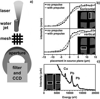
The X-ray source size is not necessarily connected to the electron beam source size. However, we are able to observe the X-ray source size, both with and without prepulses, which is important for applications (Loupias et al., Reference Loupias, Perez, Benuzzi-Mounaix, Ozaki, Rabec, Gloahec, Pikuz, Faenov, Aglitskiy and Koenig2009; Pikuz et al., Reference Pikuz, Chefonov, Gasilov, Komarov, Ovchinnikov, Skobelev, Ashitkov, Agranat, Zigler and Faenov2010). In Figure 6, the CCD is arranged in line with the converging laser beam, to give indications of the X-ray source depth in the target, also its vertical extent. Approximately 300 laser shots were needed to produce the images, which yield multi-shot average measurements. Without a prepulse, and by fitting a Gaussian error function to the edge blur, the observable single pulse X-ray source size full width half maximum (FWHM) is 6.77 µm (vertical dimension) and 11.3 μm (deep, in the target). The first of these values is a bound of the laser pointing stability (an issue that has been refined over the years on this laser system) (Genoud et al., Reference Genoud, Wojda, Burza, Persson and Wahlström2011), while the second is mostly attributed to the stopping range of few-keV electrons in water (Fullagar et al., Reference Fullagar, Harbst, Canton, Uhlig, Walczak, Wahlström and Sundström2007b). The addition of the prepulse increases the average FWHM source size to 14.7 µm (vertical) and 17.1 µm (deep). In these images, the pointing stability of the laser can be assumed identical both with and without the prepulse. The observed increases in the average X-ray source size on addition of the prepulse indicate one or both of the following: (1) the region of X-ray emission has increased on a single shot basis, (2) the position of X-ray generation in space has been made more random by the prepulse. The second interpretation is consistent with expected laser plasma interaction instabilities. Figure 6c shows secondary X-ray radiations, caused by the electron beams striking objects within the chamber and the chamber wall. These are not evident when using a single pulse. X-ray fluorescence lines from lead (chamber) and copper (riser pipe for the water jet, and mesh) are apparent in the histogram.
Inline measurement of multi-shot average X-ray source size. (a) shows the arrangement used to generate shadow images of a wire mesh on a CCD. (b) illustrates the edge blurring for the respective edges, shown as insets, from which the average source size is deduced (see text). (c) shows a histogram of events that appear in the inset region of interest (i.e., in the shadows of the wire mesh) when using a double pulse structure.

The charge of the beam per laser shot was estimated by positioning a 3.5 mm internal diameter ferrite toroid about 5 mm from the target in the path of the electrons, with two turns of wire on the toroid serving as a readout coil. After calibration and when generating electron emission using prepulses (allowing for radiofrequency pickup from synchronous components of the laser system, typically Pockels cells), the observed voltage transients indicated an emitted charge of as much as about 6 pC through the solid angle of the toroid which agrees well with the results found by Wang et al. (Reference Wang, Liu, Cai, Wang, Liu, Xia, Deng, Xu, Leng, Li and Xu2010). Other charged particles, their absorption in the residual gas and disturbances due to the plasma explosion can influence these measurements (Hidding et al., Reference Hidding, Pretzler, Clever, Brandl, Zamponi, Lübcke, Kämpfer, Uschmann, Förster, Schramm, Sauerbrey, Kroupp, Veisz, Schmid, Benavides and Karsch2007); nevertheless the signal polarity was as expected for electrons, and the measurement gives at least an indication of the charge.
A lower bound on the electron energy is easily obtained by observing X-ray fluorescence lines excited from different elements as observed using the CCD (Fullagar et al., Reference Fullagar, Uhlig, Walczak, Canton and Sundstrom2008). The beams' ability to penetrate different materials (Berger et al., Reference Berger, Coursey, Zucker and Chang1998), and the angular properties of associated scatter gave further indications, consistent with the magnetic deflection method below.
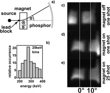
The shadow of a rectangular lead wire was projected onto a Kodak Lanex screen filtered by 110 µm of aluminum, with a 10 mm long, 27 mT calibrated electromagnet between the wire and the screen (Fig. 7). The spectral sensitivity of a similar arrangement has been characterized by others and is maximal in the approximate range 300–900 keV (Glinec et al., Reference Glinec, Faure, Guemnie-Tafo, Malka, Monard, Larbre, De Waele, Marignier and Mostafavi2006). For this experiment, we used 17 mJ in each laser arm with minimum duration p-pulse, about 20 ps relative delay, and aspirator vacuum in a 15 cm diameter transparent chamber. The shadow edge is observed to shift by up to 7.7°, corresponding to relativistically corrected electron energy of about 280 keV. The instabilities seen in earlier figures make these measurements challenging, yet they provide a clear demonstration of the nature of the beam, also a direct indication of its energy. The comparable level of shadow edge blurring when the magnet is switched on and off, or its polarity reversed, indicates that the single-shot electron energy distribution is narrow compared to the sensitive energy range of the screen. Also, the observed deflected shadow edges show surprisingly little positional variation from one successful shot to the next. The corresponding energy analysis leads to the result in the histogram inset in Figure 7. Although modest, these shot-to-shot energy differences substantially account for the edge blurring observable when the magnetically deflected images are averaged, also shown in Figure 7.
Magnetic deflection of electron beams, projected on a fluorescent screen. (a) sketches the experimental setup, using a 15 cm diameter transparent cylinder, a 10 mm long, 27 mT electromagnet and a lead block placed before the magnet that casts a shadow through it. (b) histograms the inferred energy of individual shots. The relativistically corrected energy was determined from displacement of shadow edges. (c) and (d) show examples of single shots used in this approach. (e) shows the average of 25 shots, in which the essentially modest broadening of the edge shadow supports the energy histogram in panel b).

We have repeated this experiment, with similar results, though in which experimental differences led to 6.3° beam deviation when applying the same field, corresponding to 390 keV electron energy. These energies correspond well with the observations of Wang and co-workers under high vacuum with an aluminum target (Wang et al., Reference Wang, Liu, Cai, Wang, Liu, Xia, Deng, Xu, Leng, Li and Xu2010).
REMARKS
During the transition from a high power, high contrast ratio but low repetition rate laser system to a commercially available 3 mJ 1 kHz system with a 10% temporal prepulse due to leakage in the cavity we observed similar collimated electron beams. The experimental setup was otherwise comparable. These reduced intensity conditions suggest continued exploration of the electron beams for a range of applications, though they should also be recognized as a radiation safety hazard and potential source of secondary radiations when studying laser plasma X-ray sources. Low atomic number materials are advisable on the inner walls of target chambers, to minimize hard secondary radiation and slow the electrons to rest.
For further experiments, the round water jet has proven to be entirely satisfactory in terms of stability, target smoothness, controllability of laser-target interaction geometry and simplicity of operation.
The mechanistic origin of the fast electron beams is not fully understood. It can be assumed that a continuum of plasma densities is encountered by the second laser pulse. Also, based on increases in the X-ray source size measurements, as shown in Figure 6, it appears that length scales on the order of about 10 µm are operative in the laser-plasma interaction region on the timescale of the interpulse delay, corresponding to supersonic plasma expansion. The data in Figure 2 shows that conditions required for effective X-ray production by Brunel (vacuum) heating (Brunel, Reference Brunel1987; Fullagar et al., Reference Fullagar, Harbst, Canton, Uhlig, Walczak, Wahlström and Sundström2007b) are disrupted on a timescale of only about 5 ps, which together with the undisturbed X-ray source size of 6.77 µm implies velocities on the order of 1.4 × 10⁶ ms−1. While the laser waist is doubtless somewhat smaller on a single shot basis, this high velocity indicates that, with regards to destroying the conditions necessary for the Brunel mechanism, the prepulse merely perturbs the motion of electrons at the sharp plasma gradient, which seems consistent with the presumed mechanism for the X-ray generation (Fullagar et al., Reference Fullagar, Harbst, Canton, Uhlig, Walczak, Wahlström and Sundström2007b). Given inter-pulse delays of the order 10–100 ps there is sufficient time for the establishment of a plasma plume of the required dimension. For the second (p-polarized) pulse at increasing depths within the plasma plume, different mechanisms exist that can lead to pulse self-modulation, self-compression, and filamentation (Max, Reference Max1980; Sjögren, Reference Sjögren2002).
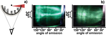
In Figure 8, the laser-target interaction is at almost grazing incidence, with the second pulse in the usual p-polarization. The pattern of accelerated electrons striking the fluorescent screen indicates the directionality of the electron acceleration process occurring in the target, likely also the electron density perturbations and intense local electromagnetic field gradients immediately before, during and after the acceleration. It is apparent that the fluorescence intensity pattern represents a potentially quantifiable observation of the complex and unstable dynamics associated with the transversal of the second pulse through the preplasma and its interaction with the critical surface (Naumova et al., Reference Naumova, Sokolov, Nees, Maksimchuk, Yanovsky and Mourou2004). The future use of few cycle pulses with carrier envelope phase stabilization (Mathur et al., Reference Mathur, Rajgara, Dharmadhikari and Dharmadhikari2008; Sansone et al., Reference Sansone, Benedetti, Caumes, Stagira, Vozzi, De Silvestri and Nisoli2006) might be critical for such studies and could perhaps lead to satisfactory control of the electron beams.
(Color online) Externally viewed video stills of electron distributions, using grazing laser incidence on the target jet. (a) sketches the setup, with water jet, 110 μm aluminum filter and optically fluorescent screen in a transparent vacuum cylinder with 6 cm diameter. (b) shows examples of complex single shot electron distributions.

The conditions obtained have long been recognized as suitable for the absorption of light by its conversion to electron plasma waves near the critical density (Kruer, Reference Kruer1975). Plasma wave breaking, associated with critical surface rippling and cavity formation may occur in these circumstances (Tajima & Dawson, Reference Tajima and Dawson1979; Estabrook, Reference Estabrook1976; Estabrook et al., Reference Estabrook, Valeo and Kruer1975). Our observed electron acceleration to about 280–390 keV in apparent distances of about 10 μm (50 GeV/m) is comparable with laser plasma wakefield acceleration experiments (Jaroszynski et al., Reference Jaroszynski, Reitsma, Ersfeld, Jaroszynski, Bingham and Cairns2009; Lundh, Reference Lundh2008; Steinke et al., Reference Steinke, Henig, Schnürer, Sokollik, Nickles, Jung, Kiefer, Hörlein, Schreiber, Tajima, Yan, Hegelich, Meyer-ter-Vehn, Sandner and Habs2010). With these considerations in mind, it is not unlikely that our double pulse experiments have certain aspects of underlying physics in common with laser plasma wakefield acceleration.
CONCLUSION
Double laser pulses impinging on a water jet target with the second pulse in p-polarized geometry, create about 280–390 keV electron beams when using inter-pulse delays in the range from tens of picoseconds to nanoseconds and longer. The beams are generated at laser intensities in the range of about 1015–1018 Wcm−2 in a helium atmosphere at ambient pressure or water aspirator vacuum and are favored by laser pulses of near transform-limited duration. Their appearance can be symptomatic of poor temporal contrast in laser systems of the kind often used for X-ray plasma generation. Conditions for angularly reproducible generation of the fast electron beams are far harder to achieve than for stable X-ray generation using a temporally isolated p-polarized laser pulse. The high electron energies represent a significant radiation hazard and motivate the use of low-Z materials for the inner walls of future target chamber constructions. They also represent a potential source of confusion if only point radiation detectors are available, and if care is not taken to discredit secondary radiations. If a suitable degree of control can be obtained, the observed about 280–390 keV electron beams are likely to prove useful in ultrafast electron imaging and scattering applications.
ACKNOWLEDGEMENTS
We especially thank the following individuals, who assisted in day-to-day laser operation over the period from 2005 to 2008 when the experiments took place: A. Persson, E. Pourtal, O. Lundh, F. Lindau, Y. Glinec, G. Genoud, and M. Harbst. This work has received funding from the Swedish Consortium for Artificial Photosynthesis, the Swedish Kungliga Fysiografiska Sällskap, the Swedish Energy Agency, the Knut and Alice Wallenberg Foundation, the Swedish Research Council, a Linneus grant awarded to the Lund Laser Centre and the ERC Advanced Investigator Grant No 226136. J. Uhlig and M. Walczak acknowledge financing through the MAXlas project, under the Sixth European Framework Programme contract number MEST-CT-2005-020356.