1.0 INTRODUCTION
When the vehicle re-enters into the atmosphere, it would encounter a serious aerodynamic environment(Reference Pezzella1), and many active and passive concepts have been proposed and studied in order to decrease the drag force around the tip of the vehicle, as well as the combustion chamber inter walls(Reference Zhu, Peng, Xu and Jiang2). The design of the thermal protection system is very critical for the vehicles(Reference Riccio, Raimondo, Sellitto, Carandente, Scigliano and Tescione3). For recent advances in this field, Wang et al.(Reference Wang, Sun, Huang, Li and Yan4) summarised the research progress of experimental investigations on the drag and heat flux reduction induced by the forward-facing cavity, the opposing jet, the aerospike, the energy deposition and their combinational configurations. Four major groups, namely geometrical, mass injection, energy deposition and magneto aerodynamic techniques, were summarised by Karimi and Oboodi(Reference Karimi and Oboodi5). In 2018, Badiger and Saravanan(Reference Badiger and Saravanan6) studied the heat flux characteristics within and outside a forward-facing cavity using the shock tunnel experiments, and the frequency analysis for flow oscillations was performed using the fast Fourier transformation. Later, Sun et al.(Reference Sun, Huang, Ou, Zhang and Li7) summarised the research progress on their drag and heat flux reduction mechanisms from the point of view of numerical simulation, and the research information on the combinational concepts have been provided at the end of this survey.
For the active approaches with regards to additional jet, the consumption of large amounts of energy and noble gas can be mentioned as drawbacks due to great challenge in engineering application. Shen et al.(Reference Shen, Liu and Yin8) investigated the drag and heat flux reduction efficiency of unit mass opposing jet in a supersonic blunt body by means of the CFD approaches, and the effects of the jet pressure ratio and the jet temperature were taken into consideration. In 2015, Huang(Reference Huang9) provided a detailed review on the drag and heat flux reduction induced by the counterflowing jet and its combinations, namely the combination of the counterflowing jet and a forward-facing cavity, the combination of the counterflowing jet and an aerospike, and the combination of the counterflowing jet and energy deposition. In order to quicken its engineering implementation, the counterflowing jet was put forward to a variable blunt hypersonic vehicle(Reference Li, Huang, Lei and Wang10) and a hypersonic lifting-body vehicle(Reference Deng, Xie, Huang, Dong and Zhang11), respectively. However, these investigations have only been conducted by means of the CFD approaches, and its experimental and flight tests should be carried out in order to verify the accuracy of the numerical results. Guo et al.(Reference Guo, Lin, Bu, Bai and Chao12) studied the heat transfer reduction induced by the counterflowing jet parametrically in order to select an optimal configuration for the thermal protection system. Nowadays, some novel jet concepts have been proposed and investigated, i.e. pulsed jet studied by Zhang et al.(Reference Zhang, Huang, Li, Yan and Moradi13), a forward-facing array of micro-jets studied by Gerdroodbary et al.(Reference Gerdroodbary, Imani and Ganji14). Additionally, a combinational concept between the opposing jet and the nozzle was developed and investigated by Bibi et al.(Reference Bibi, Maqsood, Sherbaz and Dala15), and the influence of the nozzle configuration on the drag reduction efficiency was evaluated.
In comparison, a passive approach such as the use of aerospike has proved to be a simple and effective technique in reducing both the drag and aerodynamic heating for hypersonic flights(Reference Li, Sun, Xia and Li16), and Ahmed and Qin summarised the aerothermodynamics of spiked hypersonic vehicles in 2011(Reference Ahmed and Qin17). Its successful flight test was provided by OneSpace Science and Technology CO. Ltd. in China on May 17, 2018(Reference Deng, Wang, Zeng and Qian18). The spike mounted on the stagnation region leads to a conical-shape shock wave instead of a bow one(Reference Huang, Li, Yan and Zhang19). Recently, Huang et al.(Reference Huang, Chen, Yan, Yan and Du20) gave a detailed survey on the drag and heat flux reduction induced by the spike and its combinations, namely the combination of the spike and the aerodisk or jet. Moradi et al.(Reference Moradi, Mosavat, Gerdroodbary, Abdollahi and Amini21) investigated the influence of the jet direction on the thermal protection induced by the combinational spike and jet concept numerically. Eghlima et al.(Reference Eghlima and Mansour22,Reference Eghlima, Mansour and Fardipour23) studied the drag and heat flux reduction induced by the combination of spike and counterflowing jet at high Mach number flow. Qu et al.(Reference Qu, Sun, Bai, Zuo and Yan24) investigated the heat load reduction induced by the combinational spike and opposing jet concept numerically as well. Further, Ou et al.(Reference Ou, Yan, Huang and Zhang25) optimised the combinational spike and counterflowing jet concept based on the parametric study. Qin and Xu(Reference Qin and Xu26) introduced a cooling jet on the aerodome and double-aerodome concepts, and over 45% heat flux reduction was obtained by introducing a cooling jet on the double-aerodome concept. The conjugate heat transfer approach was employed by Zhu et al.(Reference Zhu, Chen, Li, Musa and Zhou27) to study the drag and heat reduction induced by the combinational lateral jet and spike concept, and they further investigated the drag reduction and thermal protection mechanism induced by a novel combinational spike and multi-jet strategy(Reference Zhu, Li, Gong, Chen and Xu28). Gerdroodbary et al.(Reference Gerdroodbary, Imani and Ganji29,Reference Gerdroodbary30) studied the heat flux reduction induced by an opposing jet issuing from the root of the spike in detail. Huang et al.(Reference Huang, Yao and Shan31) developed a combined spike and rear opposing jet configuration, and they investigated its drag and heat reduction efficiency through the CFD method. Recently, Huang and Yao(Reference Huang and Yao32) proposed and numerically investigate a novel non-ablative thermal protection system, and it consists of the spike, the front and rear jets. In their work, the influences of the length of the spike, the total pressure ratio and sizes of the front and rear jets on its heat reduction efficiency were evaluated, and its feasibility and advantage in the future engineering application is obvious.
To the best knowledge of the authors, the position of the lateral jet, as well as its number, has rarely been taken into consideration in the open literature when applying the jet technique towards aerospike, and the lateral jet concept owns a great superiority over the longitudinal jet one proposed in our previous studies because the bow shock wave formed ahead of the spike could be pushed farther away from the wall. Therefore, the influences of such factors on the drag force reduction mechanism of a blunt body have been studied numerically in this paper as organised as follows, and their effects on the heat flux reduction are not within the scope of this paper. First, the physical model, as well as the numerical approaches, is presented in Section 2. Then, the results obtained by the numerical simulation are detailedly illustrated in Section 3, as well as the discussion on the flow field properties. At last, some conclusions have been given in Section 4.
2.0 PHYSICAL MODEL AND NUMERICAL APPROACHES
2.1 Physical model
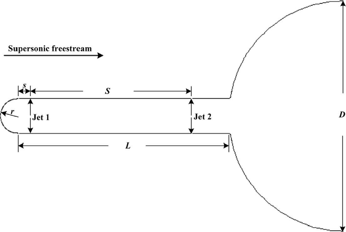
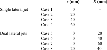
The physical model consists of two parts, namely being a hemispherical nose measured to be D = 80mm in diameter with a spike having a cylindrical body of L = 74mm in length and a hemispherical nose, see Fig. 1. This picture shows the schematic diagram for the physical model employed in the current study, and the spike installed at the stagnation point is of a hollow structure with its outer radius being r = 6mm. For the single lateral jet, the width of the injection port is set to be 1.0mm, and that of the injection port for the dual lateral jets is set to be 0.5mm in order to make the injection area being constant. In this study, the locations of the first and second lateral jets vary in order to test its effect on the drag force reduction of the blunt body, and there are four cases arranged for the single lateral jet, as well as for the dual lateral jets, see Table 1. Table 1 summarises the detailed information for the cases studied in the current study, and the first lateral jet locates very close to the tip of the spike for Cases 5, 6 and 7.
Schematic diagram for the physical model employed in the current study.

Detailed information for the cases studied in the current study

The air flows from left to right with the freestream Mach number being 5.9332, a static pressure of 1374.469Pa and a total temperature of 465K. The lateral jet is air with a total pressure of 5atm and a total temperature of 298K. The Mach number of the lateral jet is 2.2. These conditions are the same as those employed in the ground experimental test by Liu et al.(Reference Liu and Jiang33).
2.2 Numerical approaches
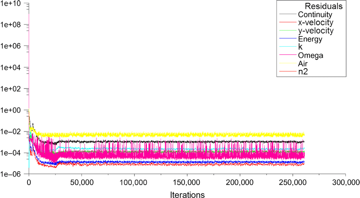
The two-dimensional axisymmetric Reynolds-averaged Navier-Stokes (RANS) equations coupled with the shear stress transport (SST) k-ω turbulence model(Reference Kummitha34–Reference Kummitha36) have been employed to numerically simulate the flow field around the blunt body equipped with the combinational spike and lateral jet concept. For brevity, the code validation, as well as its grid independency analysis, is omitted, and the researchers can refer to our previous publications, i.e., Ref. [Reference Huang, Liu and Xia37]. The convergence history for all the residuals during the numerical simulation process is shown in Fig. 2, and it is observed that all the residuals drop below 10−3.
Convergence history for all the residuals.
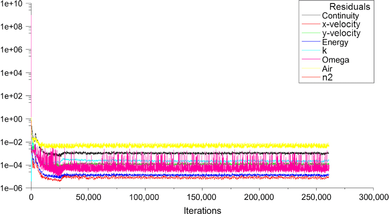
Figure 3 shows the grid system for Case 7, and only half of the computational domain has been utilised to obtain the grid distribution. The height of the first row of cells adjacent to the wall is set at a distance of 0.001mm, and the maximum value of y + is less than 0.4. This is sufficient for the boundary layer resolution.
Grid system employed in the current study (Case 7).

3.0 RESULTS AND DISCUSSION
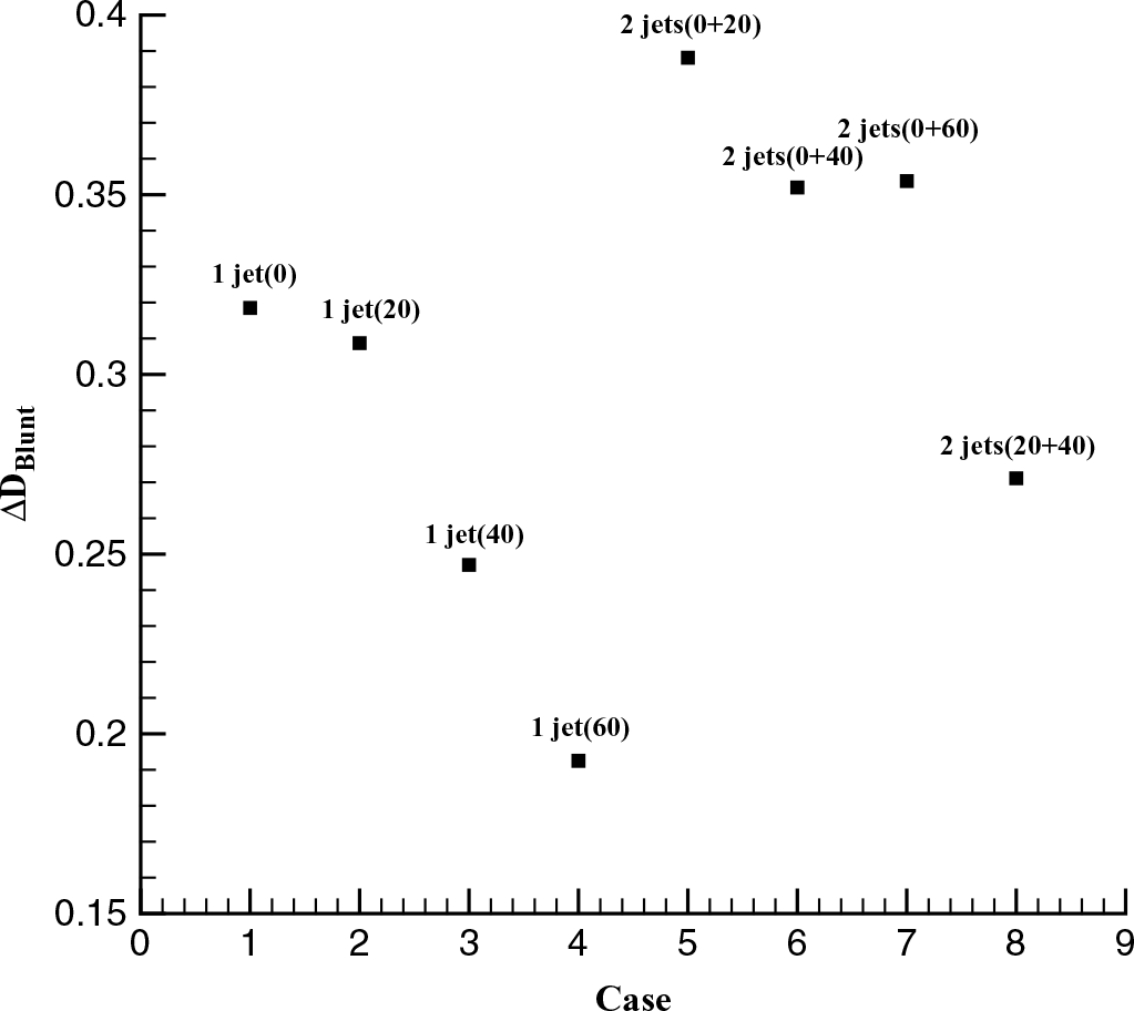
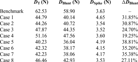
Table 2 summarises the drag force characteristics of the cases employed in the current study, and it is clearly observed that the drag force reduction of the cases with dual lateral jets is evident. This may imply that the multi-lateral jet is beneficial for the drag force reduction in supersonic flows. The value of the drag reduction percentage is larger than that of the cases with the single lateral jet, and its largest magnitude is 38.81%. It appears in Case 5, with the jet spacing being 20mm, and this is the smallest jet spacing for the multi-lateral jet considered in this paper, see Fig. 4. Figure 4 shows the ΔD Blunt comparison for cases employed in the current study. This may imply that the strong jet interaction is beneficial for the drag reduction. In Table 2, ΔD Blunt is the drag reduction percentage defined as
 \begin{equation}\Delta D_{Blunt}= \frac{D_{Blunt-Beanchmark} - D_{Blunt-Case\,i}}{D_{Blunt-Beanchmark}} \times 100\%, i=1,...,8\end{equation}
Herein,  $D_{Blunt-Beanchmark}$ is the drag force of the blunt body for the benchmark model, and
 $D_{Blunt-Case\,i}$ is the drag force of the blunt body for each case, as well as D Blunt in Table 2. At the same time,
 $D_{T}$ represents the drag force of the blunt body equipped with the combinational spike and lateral jet concept, and D Spike is the drag force of the spike for each case. It is observable that the drag force of the blunt body occupies a large portion of the total drag force for the whole physical model, and its percentage is almost above 90.0% for all cases studied in the current study. This means that the static pressure distribution along the blunt body should be decreased in order to reduce its drag force. Further, it is observed that the drag force reduction is more influential when the drag force of the blunt body occupies a smaller portion of the total value for the whole physical model.
ΔD Blunt comparison for cases employed in the current study.

Drag force properties of the cases employed in the current study
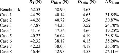
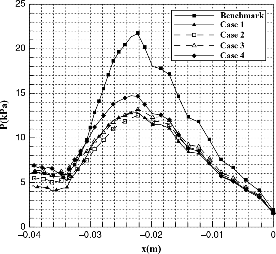
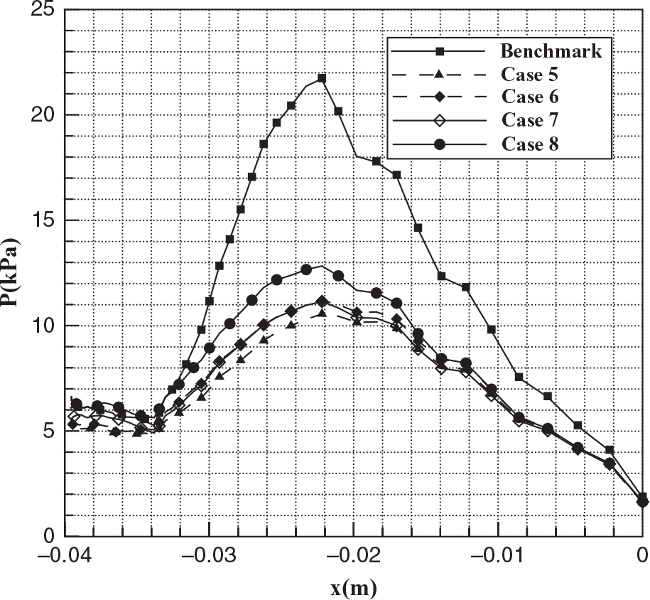
In order to explore the drag reduction mechanism of the combinational spike and lateral jet concept, the static pressure distribution along the wall of the blunt body for each case is extracted from their respective flow field, see Figs. 5 and 6. It is evident that the static pressure decreases sharply when compared with that of the benchmark model, especially on the reattachment point of the shock wave generated from the tip of the spike. With the increase of the distance between the tip of the spike and the location of the lateral jet for cases with the single orifice, the static pressure fails to decrease monotonously, see Fig. 5. It is clearly shown that the static pressure along the wall of the blunt body for Case 4 is the largest among the cases with the single lateral jet, and this phenomenon is consistent with the results summarised in Table 2. The drag force of the blunt body for Case 4 is 47.56N, with a reduction percentage being only 19.25%.
Static pressure distributions along the wall of the blunt body for cases with the single lateral jet.

Static pressure distributions along the wall of the blunt body for cases with the dual lateral jets.

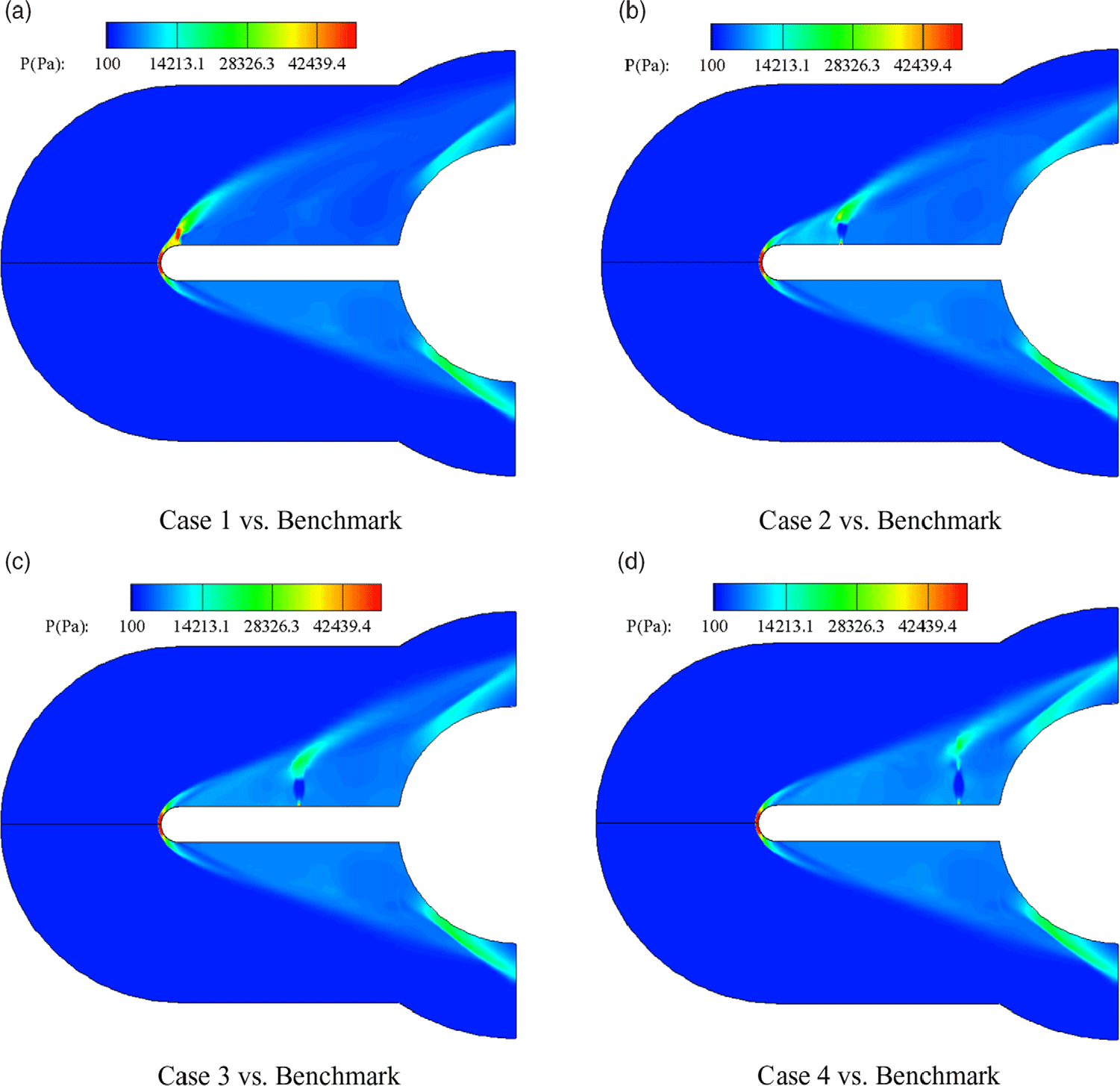
This can be explained further by the flow field properties around the combinational spike and lateral concept, see Figs. 7–9. Figures 7 and 8 show the static pressure and temperature contour comparisons for cases using the single lateral jet with the benchmark model, and Fig. 9 presents the corresponding streamline and vortex structure. It is obvious that the lateral jet penetrates deeper into the free stream when its location moves downstream, see Fig. 7, and this implies the weakening trend of the interaction between the leading shock wave and lateral jet. The impact of the leading shock wave decreases with the increase of the distance between the tip of the spike and the lateral jet location. The flow field formed by the lateral jet is nearly the same as that observed in the transverse injection in supersonic crossflows, considered as detrimental for the drag force reduction. At the same time, it is observed that the pressure intensity at the reattachment point of the leading shock wave decreases due to the employment of the lateral jet, especially when the jet positively moves away from the surface of the blunt body.
Static pressure contour comparison for cases with the single lateral jet.

Static temperature contour comparison for cases with the single lateral jet.

Streamline and vortex structure comparison for cases with the single lateral jet.

Further, it is noticed that the temperature near the walls of the spike and the blunt body decreases with jet issuing, see Fig. 8, and this is due to the recirculation zone formed near the wall of the spike and at the corner formed by the spike and the blunt body, see Fig. 9. It is observed that the vortex formed on the wall of the spike disappears while the one on the blunt shoulder enlarges when the location of the lateral jet moves downstream, and the flow separation zone formed by the vortex is induced by the great pressure gradient. Due to the existence of the blunt body, the vortex structure formed by the combinational spike and lateral jet concept is different from that of the transverse jet observed in Ref. [Reference Huang and Yan38]. The recirculation region formed at the corner between the spike and the blunt body decreases as well when the location of the lateral jet moves downstream, and the vortex just downstream of the lateral jet merges with the corner vortex when s = 60mm, namely Case 4 employed in the current study, see Fig. 9(e). The size of the corner vortex increases accordingly.
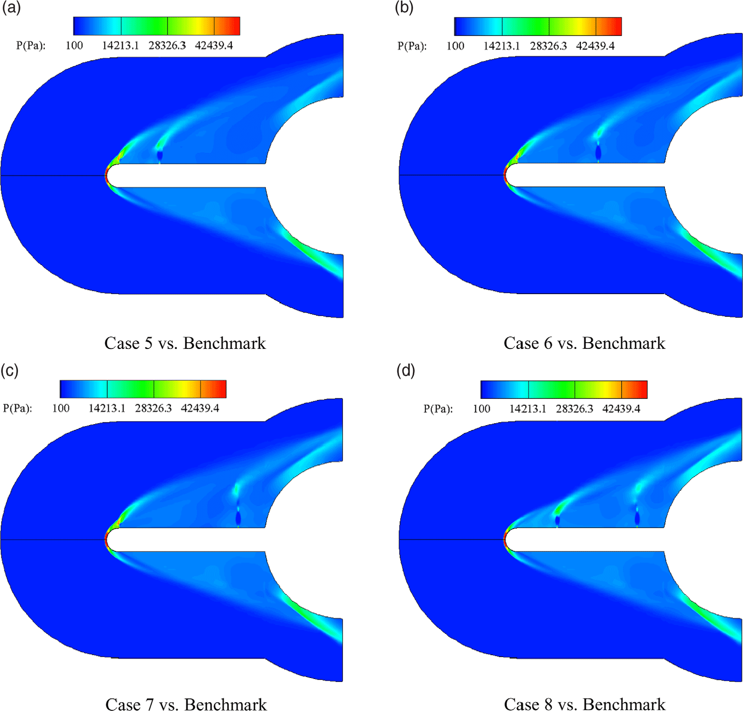
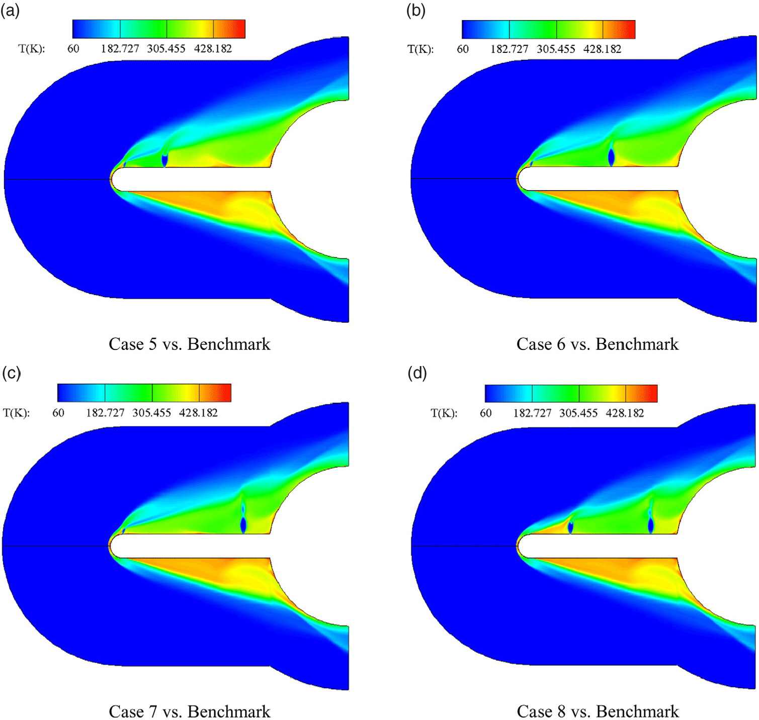
Figures 10 and 11 depict the static pressure and temperature contour comparisons for cases with the dual lateral jets respectively, and Fig. 12 represents the streamline and vortex structure comparison. In Figs. 10 and 11, likewise, the upper figure shows the parametric contour for the case with the dual lateral jets, and the lower figure shows the parametric contour for the benchmark model. It is clearly observed that the pressure intensity at the reattachment point deceases much more when compared with the benchmark model. However, when the location of the first lateral jet moves downstream, the pressure intensity at the reattachment point increases again, see Fig. 10(d), and its drag force reduction is even worse than that for cases with the single lateral jet. This conclusion can be obtained from Fig. 6, as well as Table 2 and Fig. 4. In Table 2 and Fig. 4, it is obvious that the maximum drag force reduction takes place in Case 5, and its percentage is 38.81%. This implies that the interaction between the leading shock wave and the first lateral jet has a great impact on the drag force reduction, and the drag force reduction is more evident when the interaction is stronger. At the same time, it is observed that the second lateral jet penetrates deeper into the free stream due to the blockage of the first one, and the interaction between the two injections is inconspicuous because of the spacing between two jets being small. This phenomenon can be also seen in the flow field induced by the cascaded fuel injectors in supersonic flows, see Ref. [Reference Huang, Li, Yan and Moradi39], and the Mach disk shape has been disturbed by the interaction of the shock wave system as well.
Static pressure contour comparison for cases with the dual lateral jets.

Static temperature contour comparison for cases with the dual lateral jets.

Streamline and vortex structure comparison for cases with the dual lateral jets.

Further, the static temperature on the walls of the spike and the blunt body is much lower than that for cases with the single lateral jet, especially for cases with the first lateral jet locating near the spike tip, and this is because of the large vortexes generated near its side wall, see Fig. 12. At the same time, the number of the vortices increases as well.
4.0 CONCLUSIONS
In this paper, the drag force reduction induced by the combinational spike and lateral jet concept was studied numerically by means of the two-dimensional axisymmetric compressible Navier-Stokes equations coupled with the SST k-ω turbulence model, and the influences of the location of the lateral jet and its number on the drag force reduction of a blunt body were evaluated. We have come to the following conclusions:
(1) The dual lateral jets show a much more promising drag force reduction when compared with the single lateral jet, and its effect depends on the location of the first lateral jet and the organization of the lateral jets. The maximum drag reduction percentage is 38.81% in the range considered in the current study.
(2) The drag force reduction is more evident when the interaction between the leading shock wave and the first lateral jet is stronger. When the first lateral jet is located near the tip of the spike, the drag force reduction is more evident, and this is due to the strong blockage of the first lateral jet from the free stream. Therefore, the second lateral jet could penetrate deeper into the free stream.
(3) The static temperature near the walls of the spike and the blunt body is lower for the dual lateral jets due to the larger recirculation zones formed by the vortices.
Conflict of interest statement
The authors declare there is no conflict of interest regarding the publication of this paper.
Data availability statement
The data used to support the findings of this study are available from the corresponding author upon request.
ACKNOWLEDGEMENTS
The authors would like to express their thanks for the support from the National Key R&D Program of China (No.2019YFA0405300) and the National Natural Science Foundation of China (Nos.11972368 & 11802340). Also, the authors thank the reviewer for some very constructive recommendations on this paper.