


Advances in device design, imaging, and transcatheter techniques allow more complex transcatheter interventions in smaller and sicker patients.Reference Dryzek, Goreczny and Kopala 1 – Reference Pushparajah, Hayes, Durward, Qureshi, Austin and Rosenthal 3 The introduction of the Amplatzer Duct Occluder II (St. Jude Medical, St. Paul, Minnesota, United States of America) and its subsequent “additional sizes” modification has facilitated percutaneous ductal closure in younger patients including neonates.Reference Forsey, Kenny and Morgan 4 , Reference Kenny, Morgan and Bentham 5 Despite several reports describing echocardiography for guidance of ductal closure, two-dimensional angiography remains the mainstay imaging tool;Reference Bentham, Meur, Hudsmith, Archer and Wilson 6 , Reference Zahn, Nevin, Simmons and Garg 7 three-dimensional rotational angiography has the potential to overcome some of the drawbacks of standard angiography, and reconstructed image overlay provides reliable guidance for device placement.Reference Glöckler, Halbfaβ, Koch, Achenbach and Dittrich 8 , Reference Rigatelli, Zamboni and Cardaioli 9 This modality has been successfully evaluated in various settings including pulmonary artery stenosis, coarctation, and percutaneous valve implantation; however, experience regarding the application of three-dimensional rotational angiography in smaller patients is limited. We describe arterial duct closure solely from venous approach guided with live three-dimensional image overlay.
Case report
A 12-month-old girl (5.5 kg), born at 28 weeks of gestation with a body weight of 750 g, was referred for the closure of symptomatic patent arterial duct. Echocardiography confirmed a 3-mm duct with left-to-right shunt and left atrial and ventricular enlargement.
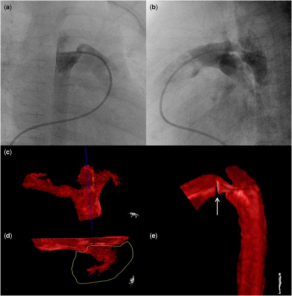
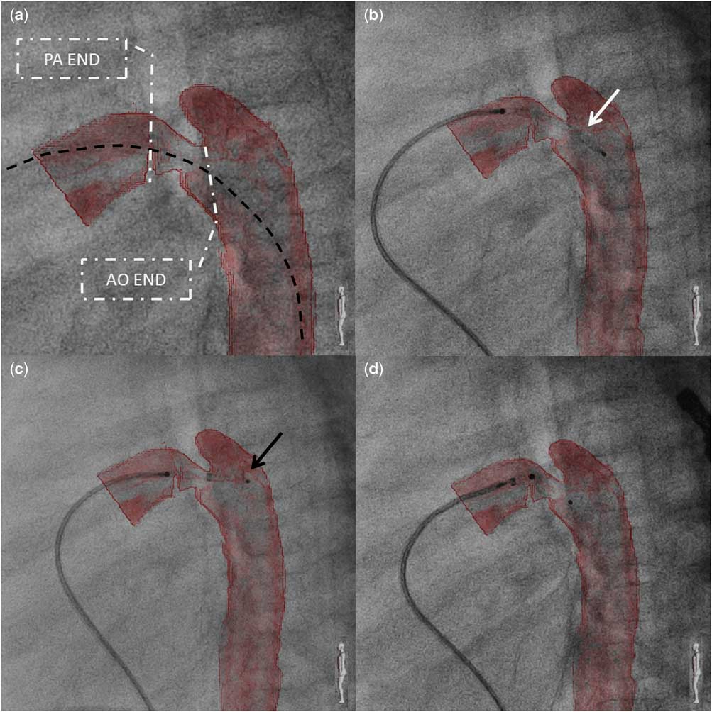
Under general anaesthesia, the femoral vein was accessed and heparin was administered. The duct was crossed from the pulmonary side with a soft 0.021″ wire, and a multipurpose catheter was positioned for rotational angiography (Supplementary movie S1; Phillips Allura, Philips Healthcare, Best, The Netherlands). A total of 122 projections were obtained, incorporating the standard duct closure views (right anterior oblique and left lateral) (Fig 1a and b). Ductal measurements showed that the pulmonary and aortic ends were 5 and 5.5 mm, respectively, and the minimal diameter was 3 mm. Ductal length was 8 mm. A 4/6 mm Amplatzer Duct Occluder II Additional Size was chosen for ductal occlusion. The raw three-dimensional reconstruction was post-processed to describe the duct and mark landing points for the occluder (Fig 1e). Subsequently, the reconstruction was overlaid on the fluoroscopy screen (Fig 2a) and used as a template for device placement and release (Supplementary movie S2). A 4-Fr delivery catheter was passed through the duct and the occluder was deployed in a typical way with the left-sided disc formed in the aorta (Fig 2c) and pulled back into the ductal ampulla. After uncovering the waist, the right-sided disc was placed near the origin of the left pulmonary artery marked on the overlay with a cut slice (Fig 2d). Echocardiography was performed to confirm unobstructed flow in the distal aortic arch and the descending aorta, as well as in the left pulmonary artery, and the occluder was released. Further course after the intervention was uneventful, and pre-discharge echocardiography showed satisfactory position of the device with no residual flow.
Rotational angiography and three-dimensional reconstruction after processing. Selected projections form over one hundred available show the duct in the two typical for biplane angiography projections – shallow right anterior oblique ( a ) and left lateral ( b ). During post-processing of the three-dimensional reconstruction, irrelevant structures were removed with “cut plane” ( c ) and “cut inside” ( d ) tools. To avoid overlapping of the left pulmonary artery (encircled on panel d ) on the duct, it was removed and its origin was marked with cut-out slice (white arrow on panel e).

Fluoroscopy with live three-dimensional reconstruction overlay. For reduction of radiation dose, device implantation was recorded with stored fluoroscopy, which resulted in lower-quality fluoroscopy images. ( a ) Post-processed three-dimensional reconstruction overlaid on fluoroscopy. Alignment of the delivery catheter (black dashed line) placed across the duct with the curvature of the duct and the descending aorta confirms accurateness of the overlay. Both aortic (AO) and pulmonary (PA) ends of the duct are clearly seen: ( b ) Amplatzer Duct Occluder II Additional Size (white arrow) was introduced to the duct through the delivery catheter with no negative influence on the accurateness of the overlay. ( c ) The distal disc (black arrow) of the occluder was partially deployed in the descending aorta. The thin nitinol wire composing the occluder hindered clear tracking of the device. Markers on both discs improved visibility and helped orientate the occluder against the overlay. ( d ) After complete deployment, the occluder sat perfectly in the duct with no suspicion of protrusion.

Discussion
In the standard approach for percutaneous closure of moderate and large arterial ducts, both the femoral vein and the artery are punctured. Arterial access is used for angiography and occasionally to cross the duct from the aortic aspect; three-dimensional rotational angiography has allowed us increased confidence to perform this procedure via the femoral vein even in challenging anatomical cases. The technique has been described for coil and device occlusion of the duct; however, for occluder implantation, serial angiography from the aortic side is preferred to monitor device position, presence of residual leak, and to exclude potential protrusion to the nearby vessels.Reference Forsey, Kenny and Morgan 4 , Reference Kenny, Morgan and Bentham 5 , Reference Baykan, Narin and Ozyurt 10
Rotational angiography required the administration of 12 ml of contrast (2.2 ml/kg), slightly more than that for standard angiography; however, overlay of the reconstructed image negated the need for additional contrast injections during deployment, positioning, and release of the device.
Catheter and wire manipulation across the duct before angiography, along with contrast injection itself, may provoke ductal spasm. The larger angiographic ductal diameter in comparison with the pre-catheterisation echocardiographic measurements reassured us that significant ductal spasm had not occurred.
Our experience with rotational angiography in other congenital heart defects show that diagnostic quality images may be obtained with dilute contrast and without rapid pacing. Most recently, we have been using 50–60% strength contrast without any negative impact on image quality. Increasing experience and confidence in the accuracy of image overlay has helped us avoid repeated angiograms and has minimised and focussed the need for intra-procedural echocardiography. Misalignment of the three-dimensional reconstructed overlay may be an issue in case of stiff devices and delivery systems. The Amplatzer Duct Occluder II and its delivery system are one of the softest systems we routinely use, and we neither anticipated nor observed any significant vessel distortion. We are now reliant on the reconstructed overlay for device release and assessment, and we do not use echocardiography as part of our routine practice.
Conclusions
Live three-dimensional image overlay for arterial duct closure provides delineation of ductal anatomy and relations, defines clear landing points for device implantation, and allows resignation of intra-procedural angiography and arterial access.
Acknowledgement
None.
Financial Support
This research received no specific grant from any funding agency, commercial, or not-for-profit sectors.
Conflicts of Interest
None.
Supplementary Material
To view supplementary material for this article, please visit http://dx.doi.org/10.1017/S1047951115001638