I. INTRODUCTION
Al–Si alloys are extensively used in automotive applications and foundry industry, owing to their excellent mechanical properties. The main exceptional property of these alloys is their light weight, and along with specific strength and toughness, it makes aluminum alloys good candidate materials for many applications. Reference Rooy1–Reference Cepeda-Jiménez, Orozco-Caballero, García-Infanta, Zhilyaev, Ruano and Carreño5 The final properties of a cast aluminum alloy depend on the final microstructure and defects that develop during solidification process. Especially, as a common impurity in aluminum alloys, the effect of iron on the mechanical properties of aluminum alloys has been reviewed extensively by Crepau, Reference Crepau6 Mbuya et al., Reference Mbuya, Odera and Ng’ang’a7 and more recently by Liu et al., Reference Liu, Mohamed, Samuel, Samuel, Doty and Valtierra8 and Gorny et al. Reference Gorny, Manickaraj, Cai and Shankar9 It is consistently reported that as Fe levels increase, the ductility of Al–Si based alloys decreases. Recently, a high magnetic field has widely been applied during phase transformations of metallic materials because it is a new approach for modification of microstructure and thus property optimization. Reference Sun, Guo, Vleugels, Van der Biest and Blanpain10–Reference Molodov, Günster and Gottstein15 It has been found that an application of a high magnetic field has significantly affected the array of the dendrite/cell during solidification process. Reference Li, Ren, Shen and Fautrelle16,Reference Li, Fautrelle and Ren17
This study extends previous work by describing directionally solidification of Al–Si alloys (i.e., Al–7 wt% Si and Al–7 wt% Si–1 wt% Fe alloys) under various magnetic field intensities and growth rates. The purpose of this study is to achieve a comprehensive understanding of high magnetic influences on α-Al dendrites and alignment of β-AlSiFe phases during directional solidification. The results showed that an application of a high magnetic field caused the deformation of the α-Al dendrites and induced the occurrence of the columnar-to-equiaxed transition (CET). It was also found that a high magnetic field was capable of aligning the β-AlSiFe phases with the appearance of the CET phenomenon. To evaluate the value of force acting on the α-Al dendrite, the Seebeck signal at the liquid/solid interface in the Al–7 wt% Si alloys was measured in situ and the results showed that the force acting on the dendrite was of the order of 105 N/m3. The modification of the α-Al dendrite morphology under the magnetic field should be attributed to the thermoelectric magnetic force (TEMF) acting on the α-Al dendrites. Moreover, the magnetization force (MF) should be responsible for the alignment of the β-AlSiFe phase under the magnetic field.
II. EXPERIMENTAL
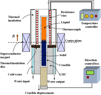
Al–7 wt% Si and Al–7 wt% Si–1 wt% Fe alloys were prepared with high-purity Al (99.999%), Si (99.999%), and Fe (99.99%) which in an induction furnace. The alloys were heated to 900 °C and magnetically stirred for 0.5 h, and then poured into a graphite mold to cast samples with a diameter of 3 mm and a length of 200 mm. The cast sample was contained in a high-purity corundum tube with the inner diameter of 3 mm and length of 200 mm for the directional solidification. The experimental apparatus consists of a static superconductor magnet, a Bridgman–Stockbarger type furnace, and a growth velocity control unit and temperature controller. The superconductor magnet could produce an axial static magnetic field with an adjustable intensity of up to 14 T. Schematic illustration of the experimental apparatus in a high magnetic field is shown in Fig. 1. The specimen contained in a corundum crucible was melted and directionally solidified in the Bridgman apparatus by pulling the crucible assembly downwards at a constant growth speed by means of synchronous motor. After 80 mm steady-state growth of the specimen, the quenching experiment was carried out by quickly withdrawing the crucible into the water-cooled cylinder containing liquid Ga–In–Sn alloy. The longitudinal (parallel to the solidification direction) and transverse sections were ground, polished, and etched to reveal the solidification microstructures, which were examined by using an optical microscope (DM 6000M, Leica, Germany). Crystallographic characteristics were measured through the electron backscattered diffraction (EBSD) in a high-resolution scanning electron microscope equipped with the EDAX's OIM EBSD Analysis System.
Schematic illustration of the Bridgman solidification apparatus in a superconductor magnet.

III. RESULTS
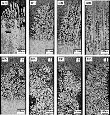
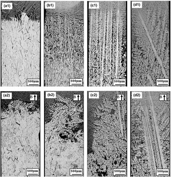
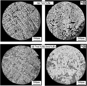
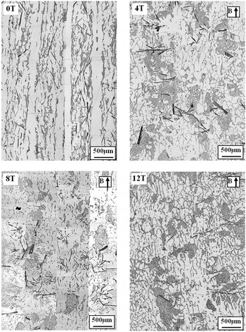
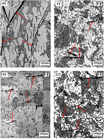
Figure 2 shows the longitudinal microstructures near the liquid/solid interface in directionally solidified Al–7 wt% Si alloys at various growth speeds without and with a 6 T magnetic field. The dendrite morphology was typical columnar in the absence of the magnetic field. However, when a 6 T magnetic field was applied, the regular dendrite was destroyed significantly. In consequence, deformed dendrites and dissociative α-Al grains formed at lower growth speeds. Moreover, the influence of the magnetic field on the dendrite morphology became weak as the growth speed increases. Figure 3 shows the longitudinal microstructures near the liquid/solid interface in directionally solidified Al–7 wt% Si–1 wt% Fe alloys without and with a 6 T magnetic field. One can notice that similar phenomena as the one in Fig. 2 occurred. The regular α-Al dendrites became irregular under the magnetic field. Figure 4 shows the transverse structures in the aforementioned two alloys without and with the magnetic field. The primary α-Al dendrite exhibited a typical columnar and uniformly distributes across the whole sample. However, when the magnetic field was applied, columnar dendrites degenerated and the freckles formed. Figure 5 shows the longitudinal microstructures below the eutectic isothermal in directionally solidified Al–7 wt% Si–1 wt% Fe alloy at 5 μm/s under various magnetic fields. Figure 6 shows the corresponding magnified micrographs in Fig. 5. In addition to the deformation of the α-Al dendrite morphology, the magnetic field also affected the array of the β-AlSiFe phases. Comparison of the microstructures without and with the magnetic field shows that the short axis of the fiber β-AlSiFe phases tended to rotate toward the magnetic field (i.e., the magnetic field) under a high magnetic field.
Structures near the liquid/solid interface in directionally solidified Al–7 wt% Si alloys at various growth speeds without and with a 6 T magnetic field: (a) 2 µm/s; (b) 10 µm/s; (c) 20 µm/s; and (d) 50 µm/s.

Structures near the liquid/solid interface in directionally solidified Al–7 wt% Si–1 wt% Fe alloys at various growth speeds without and with a 6 T magnetic field: (a) 1 µm/s; (b) 5 µm/s; (c) 10 µm/s; and (d) 20 µm/s.

Transverse structures in directionally solidified Al–7 wt% Si and Al–7 wt% Si–1 wt% Fe alloys at a low growth speed of 10 µm/s without and with a 6 T magnetic field.

Longitudinal microstructures in the solid in directionally solidified Al–7 wt% Si–1 wt% Fe alloys at a growth speed of 5 µm/s under various magnetic fields.

Alignment of the β-AlSiFe phases in the solid in directionally solidified Al–7 wt% Si–1 wt% Fe alloy at a growth speed of 5 µm/s under various magnetic fields [red arrows marking the iron-intermetallics (β-AlSiFe phases)].

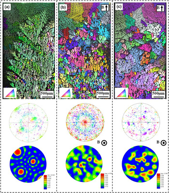
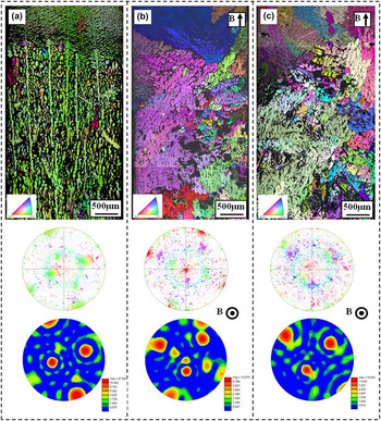
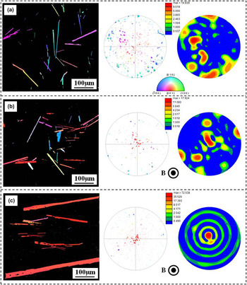
To investigate the influence mechanism of a high magnetic field on the solidification structures in detail, the EBSD technology was applied. Here, the EBSD date was rotated by 90°around the reference direction (RD) to transform the data into the more familiar reference frame with normal direction (ND) along the solidification direction. Figures 7 and 8 show the EBSD analysis in directionally solidified Al–7 wt% Si and Al–7 wt% Si–1 wt% Fe alloys, respectively. One can notice that the regular dendrite trunks were aligned along the solidification direction in the case of no magnetic fields [see Figs. 7(a) and 8(a)]. When the magnetic field was applied, the morphology of the α-dendrite transforms into equiaxed grains with random orientations [see Figs. 7(b),7(c) and 8(b),8(c)]. This further proves that the application of a high magnetic field has indeed broken the primary trunk and caused the occurrence of the CET. Moreover, the effect of a high magnetic field on the array of the β-AlSiFe phases was studied in detail by using EBSD analysis. Figure 9 shows the EBSD analysis on the β-AlSiFe phases in the longitudinal microstructures in directionally solidified Al–7 wt% Si–1 wt% Fe alloys at 5 μm/s under various magnetic field intensities. One can notice that the β-AlSiFe phases distributed randomly in the matrix with the absence of magnetic field. When a 6 T magnetic field was applied, some β-AlSiFe phases were aligned with the short axis along the magnetic field. When the applied magnetic field intensity reaches 12 T, the β-AlSiFe phase in the Al–Si–Fe alloys exhibits strongly textured morphology and the <001>-crystal direction of the β-AlSiFe phase orients along the magnetic field direction.
EBSD map and corresponding <100>-pole figures of the sample in directionally solidified Al–7 wt% Si alloys without and with a 6 T magnetic field: (a) 0 T, 5 µm/s; (b) 6 T, 2 µm/s; and (c) 6 T, 5 µm/s.

EBSD map and corresponding <100>-pole figures for structure in directionally solidified Al–7 wt% Si–1 wt% Fe alloys without and with a magnetic field: (a) 0 T, 5 µm/s; (b) 6 T, 5 µm/s; and (c) 6 T, 2 µm/s.

EBSD maps and corresponding <001>-pole figures (inverse pole figures parallel to the magnetic field direction) for the β-AlSiFe phases in directionally solidified Al–7 wt% Si–1 wt% Fe alloys at a growth speed of 5 μm/s under various magnetic field intensities: (a) 0 T, (b) 6 T, and (c) 12 T.

IV. DISCUSSION
A. Effect of a high magnetic field on the growth of α-Al dendrite
The above experimental results show that the application of a high magnetic field broke the α-Al dendrites and caused the occurrence of the CET at a low growth speed during directional solidification of the Al–7 wt% Si and Al–7 wt% Si–1 wt% Fe alloys. Moreover, it was found that the magnetic field had aligned the β-AlSiFe phases during directional solidification under the magnetic field.
Normally, two kinds of forces could produce during directional solidification under the magnetic field: one is the MF, which arose from the magneto crystalline anisotropy of the dendrite. Another is the TEMF, which is caused by the interaction between the thermoelectric (TE) current and the magnetic field. As the Al crystal owns a weak magneto crystalline anisotropy, the MF is negligible. Moreover, the effect of the magnetic field on the convection has been studied extensively and it was proven that a high magnetic field (B > 1 T) is strong enough to damp the convections. Reference Matheson, Wargo, Motakef, Carlson and Nakos18,Reference Robertson and O’Connor19 From this viewpoint, the application of a high magnetic field should enhance the formation of regular columnar dendrites. Reference Utech and Flemings20 Therefore, the break of the α-Al dendrite during directional solidification under a high magnetic field is attributed to the TEMFs acting on the solid. Further, the TEMF should be responsible mainly for the break of the dendrite.
Now, let us recall the TE magnetic effect during directional solidification under the magnetic field. It is well known that in any material a temperature gradient
 $\vec \nabla T$
produces a Seebeck electromotive force
 $S\vec \nabla T$
, where S is the TE power of the material.
Reference Shercliff21
If the gradients of S and T are not parallel, then a TE current is generated in the system. The TE current in the interdendrites has been investigated
Reference Lehmann, Moreau, Camel and Bolcato22
and the following approximation for the electric current density j
S in solid dendrites:
 $${j_{\rm{S}}} = {{ - {\sigma _{\rm{L}}}{\sigma _{\rm{S}}}\,{f_{\rm{L}}}} \over {{\sigma _{\rm{L}}}\,{f_{\rm{L}}} + {\sigma _{\rm{S}}}\,{f_{\rm{S}}}}}\left( {{S_{\rm{s}}} - {S_{\rm{L}}}} \right)G\quad {\rm{,}}$$
where σL and σS are the electrical conductivity of liquid and solid, respectively; f L and f S are the liquid and solid fractions, respectively; S L and S S are the TE power of the liquid and solid, respectively; and G is the temperature gradient. When an external magnetic field B is applied, since the TE current J TE cannot be everywhere parallel to B, thus, the Lorentz forces J TE × B (i.e., the TEMF) will produce in the dendrites:
 $${F_{\rm{S}}} = {{ - {\sigma _{\rm{L}}}{\sigma _{\rm{S}}}\,{f_{\rm{L}}}} \over {{\sigma _{\rm{L}}}\,{f_{\rm{L}}} + {\sigma _{\rm{S}}}\,{f_{\rm{S}}}}}\left( {{S_{\rm{s}}} - {S_{\rm{L}}}} \right)GB\quad {\rm{.}}$$
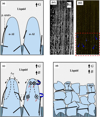
Figure 10(a) shows the schematic illustration of the growth of various phases (i.e., α-Al, β-AlSiFe, and eutectic phases) in directionally solidified Al–7 wt% Si–1 wt% Fe alloys. Figure 10(b) shows the microstructure in directionally solidified Al–7 wt% Si–1 wt% Fe alloys at 10 µm/s. It can be learned that the α-Al dendrites firstly form, and then the β-AlSiFe phase produces in the interdendrites during solidification process. Thus, during directional solidification process under an axial magnetic field, the TEMF will firstly act on the dendrites in front of the liquid/solid interface [see Fig. 10(c)] and cause the deformation of the dendrite.
Schematic sketch of the growth of α-Al dendrites, β-AlSiFe phase, and eutectic phase in directionally solidified Al–Si–Fe alloys without and with an axial magnetic field: (a) Growth of Al dendrites, β-AlSiFe phase, and eutectic phase; (b) longitudinal microstructure in directionally solidified Al–7 wt% Si–1 wt% Fe alloy at a growth speed of 10 µm/s; (c) TEMF and moment acting on the dendrites; and (d) CET of the α-Al dendrite and alignment of the β-AlSiFe phase under the magnetic field.

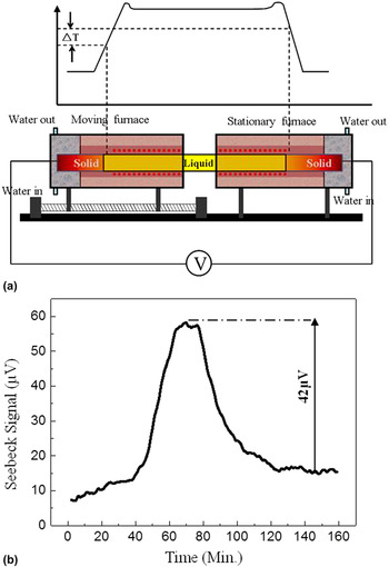
Further, to prove and evaluate the existed TEMF on the α-Al dendrite near the liquid/solid interface during directional solidification of Al–Si alloys under a high magnetic field, the Seebeck signal of the Al–7 wt% Si alloy was measured in situ. The basic principle of the interfacial TE measurement using the Seebeck technique is schematically presented in Fig. 11(a). The details of the principle had been discussed in Refs. Reference Favier, Garandet, Rouzaud and Camel23 and Reference Sen, Dhindaw, Curreri, Peters and Kaukler24. Figure 11(b) shows the Seebeck response obtained for the Al–7 wt% Si alloy at a growth speed of 5 µm/s. One can learn that a plateau was obtained on the Seebeck curve to indicate the establishment of steady state, and then the signal drops to a new steady state when furnace translation is shut off. The magnitude of signal drop, E S, corresponds directly to the effective liquid/solid TE power difference (ηsl = S S − S L). This indicates that there indeed exists a liquid/solid TE power difference during directional solidification of the Al–7 wt% Si alloy and the Seebeck signal reaches 42 μV. According to Eqs. (1) and (2), we have evaluated the magnitude of the TE current and the TEMF during directional solidification under a 10 T magnetic field. The results revealed that the magnitude of the TE current and the TEMF under a 10 T magnetic field is of the order of 104 A/m2 and 105 N/m3, respectively. In the previous work, the maximal value of the stress to break the dendrite in Al–Cu alloys is of the order of 0.1 MPa. Reference Pilling and Hellawell25,Reference Billia, Bergeon, Ngyuen Thi, Jamgotchian, Gastaldi and Grange26 Our estimation of the TEMF acting on the α-Al dendrite is of the order of 105 N/m3, and the corresponding bending stress is also of the order of 0.1 MPa in the present work. Therefore, it is reasonable to attribute the modification of the solidification structure during directional solidification in the magnetic field to the TEMF acting on the solid. Moreover, for the Al crystal, the easy magnetization axis is <111>-crystal direction, which differs from the preferred growth direction. Therefore, the MF may also enhance the formation of dendrite fragments and caused the CET.
(a) An illustration of the principle of interfacial TE measurement using the Seebeck technique; (b) Seebeck response obtained for Al–7 wt% Si alloy at a growth speed of 5 µm/s.

B. Alignment of β-AlSiFe phases under a high magnetic field during directional solidification
The above experimental results also show that the high magnetic field aligns the β-AlSiFe phases during directional solidification. According to the phase diagram of Al–Si–Fe ternary alloy, Reference Gorny, Manickaraj, Cai and Shankar9 the β-AlSiFe phase forms behind the α-Al phase and distributes at random. With the application of a high magnetic field, the primary dendrite was destroyed and the β-AlSiFe crystals tend to aligned with their <001>-crystal direction parallel to the magnetic field.
It is known that Fe has 3d unpaired electrons that give rise to the magnetism, whereas Al atom has no unpaired electrons and hence it is magnetically neutral. Therefore, it is reasonable to consider that the crystallographic anisotropically distributed Fe atoms in the β-AlSiFe crystal give rise to the crystallographic magnetic anisotropy of the crystal. It is well known that for a crystal possessing magnetic anisotropy, the application of the magnetic field will produce a MF and this force will orient the crystal. In the present work, the <001>-crystal direction is perhaps the easy magnetization axis of the β-AlSiFe crystal. Therefore, the β-AlSiFe phases are aligned with their <001>-crystal directions along the magnetic field direction when the magnetic field is applied. Previous work Reference Morikawa, Sassa and Asai27 also found perpendicular alignment in the Al–Si–Fe alloy during solidification under a 5 T magnetic field.
In the present work, the alignment of the β-AlSiFe crystal with their <001>-crystal directions parallel to the magnetic field obviously shows an energetic preference due to the enhanced magnetism in <001>-crystal directions. The driving force for the crystal alignment arises from the magnetic torque, which is proportional to the square of the imposed magnetic field intensity. Reference Sugiyama, Tahashi, Sassa and Asai28 Thus, the alignment tendency of the primary crystals enhances with the increase of the magnetic intensities (Figs. 6 and 9). Thus, on one hand, the TEMF acting on the dendrite causes the fragment of the dendrite and the occurrence of the CET. On the other hand, the magnetic field aligns the β-AlSiFe phase. As a consequence, the structure as shown in Fig. 10(d) will form during directional solidification under an axial high magnetic field.
V. CONCLUSIONS
The effect of an axial magnetic field on the structure in directionally solidified Al–Si alloys was studied, and the results obtained are summarized as follows:
-
(1) The effect of an axial high magnetic field on the morphology of the α-Al dendrites in directionally solidified Al–Si alloys was investigated experimentally. The results show that the application of the magnetic field caused the deformation of the α-Al dendrites and induced the occurrence of the CET.
-
(2) Along with the CET of the α-Al dendrites under the magnetic field, the β-AlSiFe phases were aligned with the <001>-crystal direction along the magnetic field direction.
-
(3) The Seebeck signal (E S) at the liquid/solid interface was measured in situ during directional solidification of the Al–7 wt% Si alloy and the results indicated that the value of the Seebeck signal was of the order of 10 µV.
-
(4) The modification of the α-Al dendrite morphology under the magnetic field should be attributed to TEMF acting on the α-Al dendrites. Moreover, the MF may be responsible for the alignment of the β-AlSiFe phases under the magnetic field.
ACKNOWLEDGMENTS
This work is supported partly by the European Space Agency through the Bl-inter 09_473220, National Natural Science Foundation of China (Nos. 51271109 and 51171106), and the Program for Professor of Special Appointment (Eastern Scholar) at Shanghai Institutions of Higher Learning.