I. INTRODUCTION
Cladding materials have been used for many years to impart a combination of certain physical properties (e.g., mechanical and corrosion) to the clad sheet that cannot be achieved by a monolithic material. Clad aluminum sheet is produced commercially by the roll bonding process; typical applications are brazing sheet in which a brazeable, usually, an Al–Mn 3××× series alloy, is clad with a low-melting-point Al–Si 4××× series alloy and an aerospace sheet in which a high-strength, but low-corrosion-resistant Al–Mg–Cu 2××× or Al–Zn–Mg–Cu 7××× series alloy is clad with a more corrosion-resistant dilute 1××× or 2××× alloy.Reference Dunford and Wiseey1 Roll bonding is a well-established process, but it is relatively expensive, less efficient and has limited combinations of alloys that can be roll bonded successfully. In addition to these problems, the roll bonding process is difficult to use for some products, particularly packages with varying surface friction characteristics that cause processing difficulties during rolling.Reference Dyia, Mroz and Milenin2 Continuous casting is an ideal method for producing bimetal slab or sandwich ingot with a clean metallurgically bonded interface that can be further deformed to obtain the clad sheet. This process has few restrictions with regard to the combination of alloys that can be cast, and it allows clad sheet to be produced by essentially the same hot and cold rolling routes used for conventional, monolithic alloys.
Numbers of studies have been focused on the rolling process and the deformation mechanism of the clad aluminum sheet fabricated by roll-bonding.Reference Yin and Ming3 Some fundamental work has also been carried out about the optimized experimental parameters of producing the bimetal slab by continuous castingReference Jiang and Zhang4 and the metallurgical changes occurring around the interface of the clad package during continuous casting.Reference Masahashi, Komatsu, Kimura, Watanabe and Hanada5 However, little information on the deformation of the aluminum clad sheet produced by continuous casting is found in the current literature. Although some researchers have discussed the silicon diffusion across the clad–core interface of the Al–Si/Al–Mn clad sheet during brazing process.Reference Fukuda, Ikeda, Hasegawa and Nagasawa6 Things still remain uncertain about the microstructure evolution as well as the solid-state diffusion across the interface of the clad slab during homogenization and hot rolling. What is more, in the case of producing clad automotive sheet where deformation can be extensive, it is critical that clad sheet does not delaminate. It is evident that the delamination is mainly caused by the abrupt change of microstructures and local stress concentration near the interface.Reference Sun, Song, Wang and Li7 Therefore, it is worth to improve the abrupt microstructural characteristics and lower the local stress concentration near the interface of the clad sheet.
This article mainly focuses on the phenomenon and causes that the elements diffuse across the clad–core interface and form a solid solution when the Al–Mn/Al–Si clad slab fabricated by continuous casting is homogenized and hot rolled and in-depth explains the formation of a transition area at the interface of the clad sheet introduced by the precipitation of second phase particles during the rolling deformation, which leads to the microstructure evolution and property improvement.
II. EXPERIMENTS
The present study was performed using 3003/4004 alloy clad ingot produced by continuous casting.Reference Gupta, Lee, Robert, Wagstaff, Mark and Fenton8 The nominal chemical composition in mass fraction of the as-cast clad slab is shown in Table I. With the thickness of 40 mm and the cladding rate of 12.5 pct (the volume fractions of the 4004 alloy components), the slab was prepared by machining for homogenization and rolling deformation. As the common homogenization temperature of the core alloy (3003) is approximately 615 °C which is beyond the liquidus temperature (573.5 °C) of the clad alloy (4004). The actual heat-treatment temperature is finally set according to the homogenized temperature of 4004 alloy at 510 °C. Meanwhile, considering the temperature is low for homogenizing the 3003 alloy, the time has been extended from 12 h commonly to 24 h. The bimetal slab was fabricated via hot rolling from 40 to 8 mm gauge by 16 rolling passes at temperatures of 490 °C and holding time no less than 15 min in each rolling pass. The subsequent cold rolling processing was carried out using the hot rolled 8 mm-thick plate after milling the edge. The plate was cold rolled to 2.0 mm in thickness by 3 rolling passes. The rolling reduction of every pass is 60%, 45%, and 33%, respectively, which is a severe plastic deformation for the cold rolled clad sheet.
Nominal chemical composition of the bimetal slab (mass%).

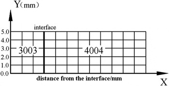
The samples for microstructural analysis were chosen from the as-cast, homogenized ingot and deformed plates before grinding, polishing and etching by Keller’s reagent and 0.5% HF, respectively. The specimens for investigation were cut from the top, center and bottom regions of the clad sheet to guarantee the stability of the clad rate. Metallographic examination was conducted throughout the interface by a MEFS multifunctional metalloscope. In the clad sheet, the silicon distribution across the interface was measured by area scanning analyzing using an EPMA-1600 electron probe microanalyzer (Shimadzu Corporation, Kyōto, Japan). The morphology and chemical composition of the second phase particles in the transition area were examined by a Zeiss Supra 55(VP) field emission scanning electron microscope (SEM; Carl Zeiss AG, Jena, Germany). Vickers hardness on the transverse area of the deformed sheet was measured by a HVS-1000 microhardness tester (Laizhou Test Machine Factory, Shan Dong, China) under the load of 4.9 N and a contact time of 15 s. The measurement locations (the intersection point of the line segment) of the rolled specimens are illustrated in Fig. 1.
Schematic diagram of locations for microhardness test of hot and cold rolling clad sheets.

III. RESULTS AND DISCUSSION
A. Homogenized microstructure of the bimetal slab
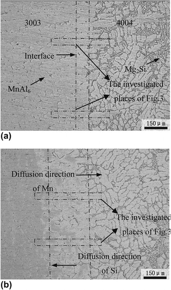
The typical microstructure of Al–Mn/Al–Si bimetal slab under the as-cast and homogenized conditions is shown in Figs. 2(a) and 2(b), respectively. As shown in Fig. 2(a), the Al–1%Mn (3003) alloy and the Al–10%Si (4004) alloy are distinctly separated and the interface is clearly distinguishable. There is no sharp delineation of the interface nor is there any evidence of porosity or oxide films. According to the previous study,Reference Marshall, Bolinguroke and Gray9 during the processing of continuous casting, a diffusion layer about 40 μm thick consisting of Si and Mn forms across the interface, which is indicated by dashed vertical lines in the figure. However, it can be observed in the clad alloy side that needle-shaped eutectic Si distributes on the matrix of primary α-Al. Some of the α-Al dendrites start to grow from the interface toward the 4004 alloy side, which are parallel to the heat flow but in the opposite direction, as shown in Fig. 2(a). These coarse phases induce the stress concentration in their sharp area, which is likely to be the source of the flaw in the consequent rolling deformation. In addition, in the core alloy side, the chilling effect of the continuous casting leads to the segregation of Mn element, due to the incomplete diffusion caused by lower diffusion coefficient of Mn in aluminum. Therefore, after the continuous casting, it is essential for the ingots to eliminate segregation and refine the coarse dendrites by homogenization.
Typical microstructure of the Al–Mn/Al–Si composite in the (a) as-cast and (b) homogenized conditions.

Optical microphotograph of homogenized clad slab [Fig. 2(b)] shows that after homogenization, the coarse dendritic structure in the clad side is redistributed as well as rounded at their sharps. Obviously, comparing with the as-cast condition, the diffusion layer in the homogenized composite is enhanced because of the eutectic Si gradually dissolving into the Al matrix and diffusing increasingly from the clad side to the core side.
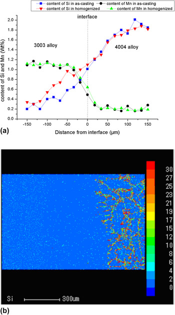
It is important to reveal the diffusion feature of Si and Mn across the interface in both as-cast and homogenized conditions. The composition profiles of Si and Mn across the different regions [as the dashed box shown in Figs. 2(a) and 2(b)] was obtained by EPMA point analysis. For persuasively, the chemical composition data acquired at the same distance from the interface are calculated to an average value and then illustrated on a graph. As shown in Fig. 3(a), the composition profiles of Si and Mn in the as-cast conditions are marked by blue and black lines, respectively. It is interested to note that the average composition of silicon decreases steadily from the clad side to the core side, while the content distribution of Mn presents a gradient ascent in the same direction. Comparing the as-cast condition with the homogenized condition, first, from the vicinity of 0.3% on the as-cast condition, the content of silicon 100 μm away from the interface rises to about 0.6% after homogenization. However, the distribution of the Mn concentration varies slowly. This means that the diffusion layer produced in the casting process does not eliminate, instead, it is maintained by the diffusion of silicon elements after homogenization and the diffusion layer is slightly broadened. Second, in the region far away from the interface (approximately ±75 μm to ±150 μm), the composition profile of the homogenized alloy presents more smoothly. It indicates that the segregation of Mn and Si in the as-cast slab is disappeared and their distribution is uniformed through homogenization treatment.
The distribution of Si and Mn elements at the diffusion layer close to the interface. (a) Si compositional profiles across the interface and (b) silicon distribution in the diffusion layer after homogenization.

The variation in the diffusion layer after homogenizing is caused by the diffusion of Si and Mn elements. There are probably two reasons to explain this effect: the first reason is that the enormous concentration difference of these elements between the two sides of the interface, especially silicon, which provides the driving force for diffusion. In addition, defects and lattice distortion around the interface area play a role of a diffusion tunnel for the migrated atoms. The second one is that the diffusion coefficient of Mn in aluminum is lower than that of Si as well as its concentration difference across the interface. Therefore, it is not obviously observed in the figure that Mn diffuses across the interface to the 4004 alloy side after homogenization.
Figure 3(b) shows the area scanning analysis of the silicon distribution in the homogenized condition, which is analyzed as averaged electro-probe micro-analyzer (EPMA) analysis. It can be seen in the left part of the graph that the blue background which represents the matrix of 3003 alloys is densely covered with considerable numbers of colored particles which represent the dispersively distributed silicon. This indicates that the diffused silicon does not form phases on the core side. Instead, they dissolve into the matrix forming a solid solution or even supersaturated solid solution in some areas with crystal defects.
B. Deformation microstructure and composite distribution of the clad sheet
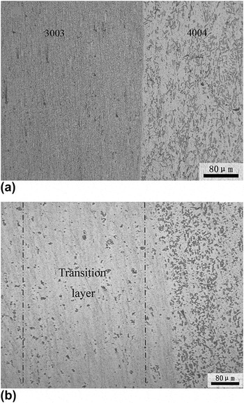
The typical microstructures at the interface region of rolled 3003/4004 composites are presented in Fig. 4. The different microstructural features between the two components exiting in the as-cast condition do not change after plastic deformation, and the distinct interface between two layers remains. In the 4004 alloy side, with the continuous thinning of the plate, the closely packed and needle-like dendrite Si phases are fragmented and rounded at their sharp area by the rolling force and distributed uniformly on the matrix. As for the 3003 alloy of the hot rolled clad sheet, the only indication is the feature of the microstructure transforming from the high density of coarse constituent particles before deformation to a finer microstructural characteristic. Comparing the microstructure of the hot rolled condition with the cold-rolled one, there is likely no obvious difference in the clad and core layers. As for the interface area, however, more second phase particles are seen and the morphology of these particles is similar to the shattered eutectic Si phases existing in the 4004 alloy side as shown in Fig. 4(b).
Microstructure of the 3003/4004 composite in the (a) hot-rolled condition and (b) cold-rolled condition.

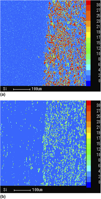
The images of silicon distribution across the interface of the clad plate after hot and cold rolling are depicted by the EPMA area analysis [shown in the Figs. 5(a) and 5(b)]. The profile of Si distribution in the hot rolled condition indicates that the hot deformation maintains the previous process of Si dissolving into the 3003 matrix forming a solid solution during homogenization. In stark contrast, silicon distribution after the cold rolling shows that instead of dissolving into 3003 alloy matrix, the migrated elements (Si) precipitate as second phase particles at the interface area and distribute dispersedly along the rolling direction. It should also be noticed in the core alloy side that the precipitations decrease in numbers along with the increase of distance from the interface, which presents a tendency of gradient distribution. Plentiful precipitations distributing along the rolling direction changes the feature of the interface from a narrow line to a precipitation bandReference Esmaeili and Lloyd10 or a gradient transition zone.Reference Zhang, Luo, Xia and Li11 The precipitation band is about 80 μm in width corresponding to the diffusion layer and its emergence improves the abrupt microstructural variation across the interface.
Clad–core interface featuring silicon distributions after (a) hot rolling and (b) cold rolling.

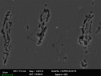
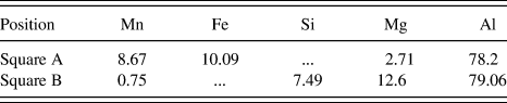
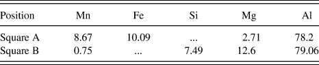
For the further examination of the second phase particles in the transition zone, analysis was carried out by SEM across the interface to acquire much more details of the precipitations. As shown in Fig. 6, the second phase particles in the transition zone can be divided into two types, which are marked A and B in the corresponding area in SEM images. The EDS analysis results illustrated in Table II show the nominal chemical composition of these particles in mass fraction. For the calculated atom ratio of Al and Mn, Fe in square A is close to 6:1. It is reasonable to infer the A particle is Al6 (Mn Fe) intermetallic which originally existed in the as-cast core alloy. As observed in this figure, the initially herringbone Al6 (Mn Fe) particles are elongated and crushed by the deformation force and distributed parallel to the rolling direction. Due to their brittle and hard feature, parts of these phases fall off during polishing leaving some tunnels on the matrix, as shown in Fig. 6. The distribution of B particles is the same as the A particles [Al6 (Mn Fe)] that spreading along with the rolling direction. Meanwhile, their size (about 1 μm) is smaller than that of the A particles (about 30 μm). The EDS analysis result from point B shows that the Mg/Si ratio is 1.7 which is close to the Mg/Si ratio of the β′ precipitation of Mg2Si phases of about 1.68.Reference Rack12 It is reasonable to indicate that the small particles are composed of β′-Mg2Si phases which are in the 4th stage of the precipitation sequence of Mg2Si.Reference Mulazimoglu, Zaluska, Paray and Gguzleski13 The precipitation of B particles (Mg2Si) after cold rolling might depend on combining the diffused silicon with the original solute Mg in the core alloy. Since the Al6 (Mn Fe) particles initially exist in the 3003 alloy, the newly presented transition zone may chiefly attribute to the precipitation of Mg2Si particles.
SEM micrographs of the morphological character of the second phase particles in the transition zone of the cold rolled clad sheet.

EDS analysis results for second phase particles in the transition zone (mass%).
It is worth analyzing the mechanism of the precipitation of Mg2Si particles forming the transition zone. First, the homogenization and hot rolling process have been conducted under relatively high temperature (500 and 490 °C), which would effectively raise the crucial controlling factor of diffusion—the diffusion coefficient. As a result of this, silicon in the 4004 alloy rapidly diffuses to the 3003 alloy side. In addition, the concentration difference of the silicon across the interface is another driving force for expediting silicon migration. Furthermore, the high processing temperature increases the solubility limit of silicon in aluminum, which causes an endless flow of the diffused silicon to dissolve into the 3003 alloy forming a solid solution or even supersaturated solid solution in some regions with defects. According to the thermodynamic equation of second phase desolvationReference Swalin14:
 $$\Delta G^{{\rm{\alpha }} \to {\rm{\beta + \alpha }}_1 } = {\rm{\chi }}_{\rm{B}}^{\rm{\alpha }} ({}^\Theta G_{\rm{B}}^{{\rm{\alpha }}_1 } + {\rm{RTln\alpha }}_{\rm{B}}^{{\rm{\alpha }}_{\rm{1}} } - {}^\Theta G_{\rm{B}}^{\rm{\alpha }} - {\rm{RTln\alpha }}_{\rm{B}}^{\rm{\alpha }} )\quad.$$
In the formulation, B is the solute element dissolving into the matrix; α is the parent phase, α1 represents the matrix after precipitation,  $\Delta G^{{\rm{\alpha }} \to {\rm{\beta + \alpha }}_1 }$ as the driving force of the precipitation,
 ${\rm{\chi }}_{\rm{B}}^{\rm{\alpha }}$ represents the initial quantity of component B dissolving in the parent phase,
 ${}^\Theta G_{\rm{B}}^{{\rm{\alpha }}_1 }$ is the partial molal free energy of component B in α1,
 ${}^\Theta G_{\rm{B}}^{\rm{\alpha }}$ is the partial molal free energy of component B in α,
 ${\rm{\alpha }}{\textstyle{{a_1 } \over {\rm{B}}}}$ is the activity of component B in α1,
 ${\rm{\alpha }}{\textstyle{a \over {\rm{B}}}}$ is the activity of component B in α.
It is evident from the given equation that the driving forces of the Mg2Si precipitation depend on the solid solubility of the silicon in the 3003 alloy. The cold rolling conducted under room temperature decreases the solid solubility of silicon in 3003 alloy and correspondingly adds the saturation, which consequently increases the driving forces of precipitation reaction. At the meantime, the original solute Mg precipitates from the matrix in the same way and combines with the migrated silicon to form the Mg2Si particles. Moreover, according to the nucleation theory,Reference Cabibbo, Evangelista and Vedani15 the raised precipitation driving force would also bring down the critical radius of the precipitation (the minimum size that must be obtained by atoms clustering together).
Second, the cold deformation makes a contribution to promoting the precipitation process. On one hand, the tangled and rearranged dislocations introduced by the severe plastic deformation build the subboundaries and enrich the grain boundaries more than refining the grains. The increased crystal defects provide abundant locations for heterogeneous nucleation. Just as shown in Fig. 6, the Mg2Si trends to precipitate near the phase-boundaries of the Al6 (Mn Fe) phase where high density of defects accumulates. On the other hand, according to the previous research,Reference Su, Lu and Lai16 the precipitation driving forces consist of two parts. One of them provides energies to generate the new phases for driving the diffusion. While the remaining part storages in the new phases as the surface energy which is the resistance in the precipitation process. Large amounts of the defects introduced by cold rolling could offset parts of the surface energy in the new phases. By which it means the precipitation resistance is reduced and accordingly more energy is released to precipitate new phases.
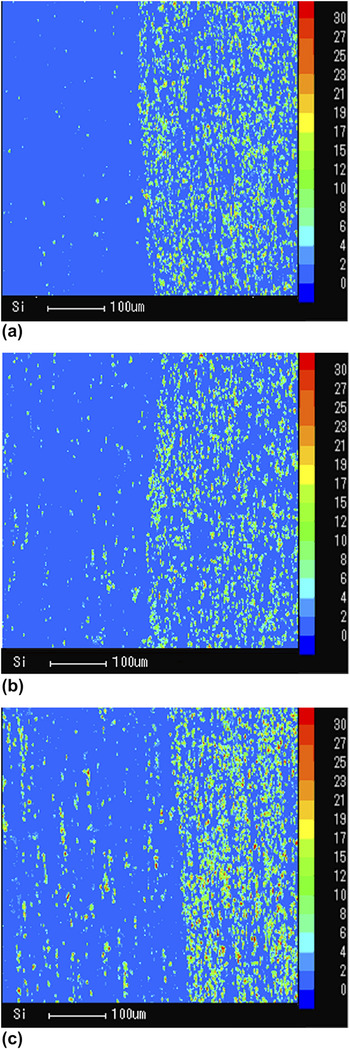
There is a typical instance of the above-mentioned effects comparing the distribution of precipitated silicon in the transition area of clad sheet rolled by different first-pass deformation rates at 20%, 40%, 60%, respectively. As shown in Fig. 7, it is evident to note that with the increasing of the first-pass rate, the quantity of the precipitated Mg2Si phases in the core side increases gradually. This result confirms the effect of severe plastic deformation on promoting the precipitation of the second phase particles. What is more, as shown in Fig. 6, the morphology of the precipitated Mg2Si phases presents to be granular rather than plate-like. There are possibly two reasons behind this phenomenon. First, the severe plastic deformation not only increases the density of the dislocations inside the grains, but also arouses the disordering of the crystal lattice in Al matrix which impedes the formation of habit plate between the precipitations and the matrix.Reference Janecek, Popov, Krieger, Hellmig and Estrin17 In addition, for the fast speed of the rolling deformation, it is inaccessible for the precipitated Mg2Si phases to grow adequately into the stable plate, but forming the rod-shape precipitate which is in the 4th stage of the Mg2Si precipitation sequence.Reference Su, Lu and Lai16
The silicon distribution in the cold rolled sheet under different rates of first pass deformation: (a) 20% deformation rate, (b) 40% deformation rate, and (c) 60% deformation rate.

C. Distribution of microhardness at the interface
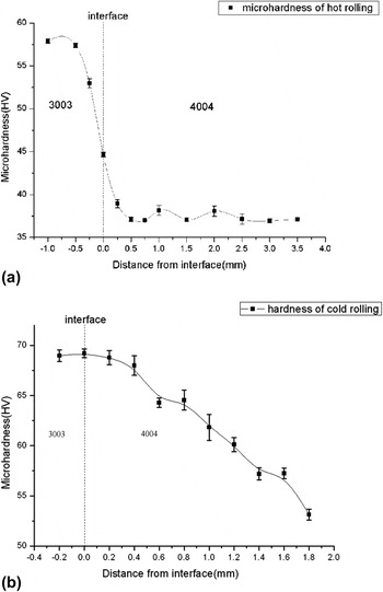
To elucidate the effect of the transition region on the mechanical properties of the clad sheet, microhardness distributions across the interface of the composites on hot-rolled and cold-rolled conditions are shown in Figs. 8(a) and 8(b), respectively. Figure 8 illustrates the distribution of microhardness both along the X direction which is parallel to the applied force, and along the Y direction (as illustrated in Fig. 1). The microhardness distribution of hot-rolled plate shown in Fig. 8(a) indicates that from a higher value at approximately 57 HV in the clad alloy, the microhardness across the interface plunges to a low value of just about 38 HV in the core side. This feature of abrupt change in the microhardness distribution is similar to the tendency around the bonding interface of the clad plate which is prepared by the traditional roll bonding technology.Reference Masoumi and Emadoddin18 Based on the experiences in practical application,Reference Gupta, Lee, Robert, Wagstaff, Mark and Fenton8 if the clad sheet is deformed into a complex shape, the abrupt change of mechanical property across the interface would possibly cause regional stress concentration and induce cracking or delaminating during deformation. On the other hand, as schematized in Fig. 8(a), the length of the line segment in every examined point reflects the fluctuation of microhardness at the same distance from the interface by calculating the average Vicker’s hardness data collected in Y direction. Although the sheet has been radically deformed by several numbers of hot rolling passes, the Vicker’s hardness fluctuates in a narrow range, which could be due to the effect of the recovery process during hot-rolling.
Distribution of microhardness on the transition area of hot-rolled (a) and cold-rolled (b) 3003/4004 plates.

In stark contrast, as illustrated in Fig. 8(b), the microhardness distribution of the cold-rolled sheet along the X direction shows a considerable change, especially in the region close to the interface. It is evident to note that the microhardness distribution in the cold-rolled sheet presents a gradient variation rather than an abrupt change. This improved microhardness distribution tendency would be attributed to the precipitations of Mg2Si particles at the interface area which reinforces the initial low-hardness 3003 alloy by the dispersion strengthening effects. Precipitation of the second phase particles not only improves the microstructure of the clad sheet by generating a transition layer but also transforms the distribution of mechanical properties to be more smooth and successive. Admittedly, an unstable fluctuation of microhardness can be seen along Y direction, which could be due to the localized stress concentration introduced by cold rolling. According to the traditional process for producing clad sheet in industry,Reference Manesh and Taheri19 the subsequent annealing heat treatment can eliminate the drawbacks caused by cold rolling. In general, despite introducing localized stress concentration, the presented transition region introduced by the precipitation of Mg2Si particles improves the main defects in the conventionally fabricated clad sheet in terms of both the microstructure and the mechanical properties.
IV. CONCLUSIONS
(1) For the Al–Mn (3003 alloy)/Al–Si (4004 alloy) clad slab fabricated by continue casting, when the composite is homogenized and hot rolled, silicon in the clad layer diffuses across the interface and dissolves into the 3003 matrix forming a solid solution.
(2) After deformation by cold rolling, the increased driving force for precipitation of the solute elements in the core alloy side along with the abundant defects introduced by the severe deformation promotes the precipitation of Mg2Si particles to form a transition area at the interface of the clad sheet.
(3) The presented transition area not only benefits the microstructure of the clad sheet but also improves the distribution of the microhardness across the interface, a tendency of gradient transition.