Introduction
Nano- and microparticles have demonstrated exceptional potential in a variety of areas, such as diagnostics, therapeutics, and energy applications. Reference Jiang and Granick1 Recent improvements in particle fabrication methods, such as the expansion of compositional flexibility and physical as well as chemical tunability, have resulted in increased functional versatility of colloidal particles. In particular, precise engineering of shape, size, surface structures, and mechanical properties has been accomplished by several processes. Reference Grzelczak, Vermant, Furst and Liz-Marzán2–Reference Park, Lahann, Jiang and Granick4 Beyond the current state of the art, the complementary control of internal (bulk) and external (surface) features has emerged as an important design parameter for multifunctional particles, where the bulk and surface of each particle are no longer isotropic in their functionality and characteristics. These anisotropic particles may feature two or more distinct compartments, controlled interfacial patterns, or compositionally distinct material domains in a single particulate entity. Reference Glotzer and Solomon5–Reference Chen, Bae and Granick15 Novel self-assembled particles, such as multifunctional particles, may find diverse applications in multiplexed bioassays, Reference Pregibon, Toner and Doyle16 vehicles for multiple therapeutic modalities, Reference Sengupta, Eavarone, Capila, Zhao, Watson, Kiziltepe and Sasisekharan17 biohybrid materials, Reference Yoshida, Roh, Mandal, Bhaskar, Lim, Nandivada, Deng and Lahann18 or microactuators. Reference Kim, Chung, Choi, Lee, Kim and Kwon19,Reference Higuchi, Tajima, Motoyoshi, Yabu and Shimomura20
Compositional bulk anisotropy may enable unique particle properties. Here, a particle configuration that features materials compartmentalized within a monolithic particle can impart entirely new properties and may be a decisive functional parameter, being similarly as important as the actual chemical makeup. Reference Park, Lahann, Jiang and Granick4 On the other hand, anisotropic surface functionalization can be realized in the form of patchy particles, where different surface patches are associated with different chemically or functionally orthogonal surface properties. Particles with this type of surface anisotropy can exhibit bipolar characteristics, such as particles that are simultaneously hydrophilic and hydrophobic, or can be used for self-assembly and drug delivery. Reference Yoon, Kota, Bhaskar, Tuteja and Lahann21–Reference Eyster, Park, Misra and Lahann23 Independent control of the compositions of individual compartments of the same particle allows for inclusion of materials with highly dissimilar sets of properties. This approach forms the foundation for the controlled release of multiple drugs with independent release kinetics (provided that each drug is loaded in a separate compartment) or a combination of fully decoupled modalities for combined imaging and therapy (theranostics) (see the article by Yhee et al. in this issue). Reference Misra, Bhaskar and Lahann24 In addition, selective surface functionalization of individual compartments remains a possibility and may lead to even more versatile and multifunctional particles.
Compartmentalized particles can be fabricated by a range of different methods. In particular, the self-assembly of block copolymers Reference Walther, Andras, Drechsler, Abetz and Mueller25,Reference Kim, Larsen and Weitz26 or the use of intended phase separation during seeded polymerizations (where two non-miscible solvents are used to create an emulsion, at the interface of which two different polymer brushes are grown on the same nucleation seed), are widely pursued approaches toward anisotropic nanoparticles. Reference Kraft, Hilhorst, Heinen, Hoogenraad, Luigjes and Kegel27,Reference Rolland, Maynor, Euliss, Exner, Denison and DeSimone28 More recently, lithographic and template-assisted methods have attracted wide attention for their great flexibility in constructing non-spherical Janus particles, such as disks, rods, and cubes. Reference Badaire, Cottin-Bizonne, Woody, Yang and Stroock29–Reference Nisisako, Torii, Takahashi and Takizawa31 Droplet-based strategies have also found use in the preparation of multifunctional particles. In some instances, microfluidic techniques were combined with photolithographic methods to prepare particles with uniform size and shape. In specific examples, this approach resulted in particles with impressive complexity of inner and outer geometries. Reference Chen, Abate, Lee, Terentjev and Weitz32–Reference Greiner and Wendorff34 However, a narrow choice of materials is available for these rather specialized approaches, and relatively large particle sizes are obtained. Further progress is needed to ensure diversification of materials choices and to augment the establishment of widely applicable processing methods. There are many excellent reviews that have focused on various methods for the fabrication of anisotropic multifunctional particles and fibers and their respective advantages and disadvantages. Reference Yoon, Lee and Lahann10,Reference Lee, Yoon and Lahann11 These methods include, but are not limited to, emulsion polymerization processes, microcontact printing, self-assembly of block copolymers, grafting, template-assisted techniques, selective surface deposition, electrohydrodynamic co-jetting, particle fusion methods, microfluidic and lithographic techniques, and phase separation-induced particle fabrication. These techniques provide a wide selection of anisotropic particle systems with unique characterizations, including selective surface modification, material incorporation, size selection, and shape diversity. However, the majority of the fabrication techniques are limited to bi-compartmental particles, and the incorporation of three or more materials, orthogonal surface patches, and therapeutics are either very challenging or not possible. Reference Glotzer and Solomon5,Reference Walther and Muller7,Reference Dendukuri and Doyle9,Reference Perro, Reculusa, Ravaine, Bourgeat-Lami and Duguet35–Reference Du and O’Reilly40 In this article, we highlight recent developments in the electrohydrodynamic co-jetting approach used for the fabrication of nano- and microparticles and fibers with multifunctional characteristics.
Compartmentalization of nanoparticles via electrohydrodynamic co-jetting
Arguably, one of the most versatile approaches toward anisotropic particles, cylinders, fibers, and fiber scaffolds is based on electrohydrodynamic (EHD) co-jetting; a technology pursued in the Lahann Lab at the University of Michigan. Reference Park, Lahann, Jiang and Granick4 This technology has been used for the fabrication of organic Reference Greiner and Wendorff34 and inorganic nanoparticles. Reference Lv, Lee, Hwang, Park, Zhang and Lahann41,Reference Lv, Lee, Li, Park, Hwang, Hart, Zhang and Lahann42 This research has been inspired by work done by Loscertales et al., wherein coaxial, electrified liquid jets were used to fabricate nano- and micro-droplets with a core–shell structure, and built upon pioneering work done by Gupta et al., where side-by-side electrospinning was used to create multifunctional, but not multicompartmental, nanofibrous meshes. Reference Gupta and Wilkes43–Reference Sun, Zussman, Yarin, Wendorff and Greiner47
Electrospraying and electrospining processes have been applied to polymer solutions to establish straightforward methods for the preparation of nano-/microparticles using high electrical voltages as driving forces for the transport of polymer solutions. Importantly, the precise control of critical polymer solution properties such as material selection, concentration, viscosity, and conductivity can result in a diverse range of sizes and shapes in the nanometer and micron range. Reference Roh, Martin and Lahann48 Building on these well-established methods, EHD co-jetting now involves the use of two or more flows that are run through parallel capillary needles in a side-by-side configuration. Thus, there is no convective mixing, and a very stable interface can be established between the two jetting solutions. Application of an electric field to the compound droplet, which forms at the outlet of the two capillary needles, results in distortion of the droplet into a stable cone and subsequent formation of an electrified polymer jet. The rapid acceleration of the viscoelastic jet with velocities on the order of 250 m/s, comparable to a rocket launch, can lead to a reduction in jet diameter by several orders of magnitude and a simultaneous increase in surface area. This induces instantaneous evaporation of the solvent and results in solidification of the non-volatile components. Because solidification is extremely fast, surface energy driven reorientation of the polymers into a thermodynamically more stable core–shell configuration is restricted, and the initial flow-determined configuration can be maintained. Thus, EHD co-jetting uses relatively simple manipulation of liquid geometries followed by rapid solidification to provide access to solid nano- and microfibers with architectures that would be otherwise impossible, or at least extremely difficult, to achieve. As a result, the particles are trapped in the initial, flow-determined compartmentalized geometry, rather than taking on the energetically most favorable constellation, which is in almost all cases a core–shell particle. Not surprisingly, however, the preparation of bicompartmental polymer particles via EHD co-jetting requires delicate control of several competing factors.
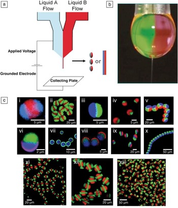
Initial work with EHD co-jetting focused on water-soluble polymers because water-based jetting systems typically exhibit lower toxicity, which is a critical factor for biomedical applications. The preparation of bicompartmental particles using the EHD co-jetting approach was first demonstrated with aqueous solutions of polyacrylic acid (PAA) or poly(ethylene glycol) (PEG). Reference Roh, Yoshida and Lahann49 The relatively high free surface energy of water results in the formation of a nearly spherical droplet, where the biphasic flow interface is maintained, and a stable cone is formed ( Figure 1 ). The compartmentalization is due to the particular manipulation of the liquid phases. However, the use of water-soluble polymers for the fabrication of particles also requires post-fabrication modification to ensure stability under physiological conditions. In the case of the above-mentioned poly(acrylamide-co-acrylic acid) (P(AAm-co-PAA)) particles, thermal imidization of carboxylic acid and amide groups provided sufficient particle stability and resulted in controllable swelling in water (volume enlargement of particles as water molecules penetrate into the bulk of the particles and interact with the polymers). Reference Bhaskar, Roh, Jiang, Baker and Lahann50
(a) Schematic description of the electrohydrodynamic (EHD) co-jetting process, which can lead to either particles (electrospraying) or fibers (electrospinning). (b) A photograph of a typical Taylor cone and jet ejection during EHD co-jetting. The interface between the two aligned polymer solutions is clearly observed. (c) Examples of particles and fibers obtained from the EHD co-jetting. Particles were composed of poly(lactic-co-glycolic acid) polymers, and a different dye was incorporated into each compartment to display their anisotropic nature. Imaging was done with a confocal laser scanning microscope. Figure adapted with permission from Reference 12.

More recently, EHD co-jetting of polymers in organic solutions has yielded anisotropic micro- and nanoparticles. In particular, the EHD co-jetting of organic solution of poly(lactic-co-glycolic acid) (PLGA) resulted in bicompartmental particles and fibers. Reference Mandal, Bhaskar and Lahann51 Because of their biodegradability, these particles constitute promising building blocks for drug delivery and tissue engineering. Reference Bhaskar, Pollock, Yoshida and Lahann52
Systematic analysis of the EHD co-jetting system reveals that both solution and process parameters have to be controlled to achieve a particular compartmentalization, shape, and size. Reference Roh, Martin and Lahann53 In addition, EHD co-jetting can be affected by a number of environmental factors, such as temperature, pressure, and humidity. Subtle alternation of these variables may lead to significant variations in particle size, shape, surface, morphology, and porosity. A wide range of PLGA particle characteristics has been achieved through variation of polymer concentration and flow rate of PLGA fluids as control parameters. Reference Roh, Martin and Lahann53 The viscosity of a polymer solution, a direct consequence of polymer concentration and molecular weight, significantly influences jet atomization and evaporation rates as well. For example, fiber architectures are preferentially prepared at higher concentrations and low flow rates, because more viscous solutions can resist the breakup of the jet. Besides changes in the solution viscosity, the addition of small surface-active molecules may alter other jetting solution properties and influence the compartmentalization, size, and shape of particles. Reference Misra, Bhaskar and Lahann24,Reference Doshi, Zahr, Bhaskar, Lahann and Mitragotri54,Reference Bhaskar and Lahann55
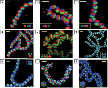
Because the capillary needle configuration primarily determines the compartment geometry of particles and fibers fabricated by the EHD co-jetting process, an increase in the number of capillaries can provide access to particles with more than two compartments. Reference Bhaskar and Lahann55,Reference Gupta and Wilkes56 The EHD co-jetting of aqueous P(AAm-co-PAA) solutions with a three-needle setup resulted in tricompartmental particles with diameters between hundreds of nanometers and a few micrometers. Reference Roh, Martin and Lahann53 On the other hand, multicompartmental fibers with as many as seven distinct compartments can be prepared by the EHD co-jetting of PLGA solution ( Figure 2 ). Reference Bhaskar and Lahann55 Combined with low flow rates and high solvent volatility, highly viscous PLGA solutions contribute to the formation of a very stable and continuous jet, which results in fibers with multiple compartments only minimally affected by perturbations during EHD co-jetting, such as humidity, air flow, charge build-up, and temperature fluctuations. Reference Bhaskar and Lahann55 Moreover, the flow arrangement as well as the nozzle geometry can influence the orientation of compartments. For example, three parallel-aligned needles in a side-by-side configuration yield sandwiched compartments, which can show all possible “isomers” of tricompartmental fibers (Figure 2a–c). On the other hand, a concentric side-by-side three-needle configuration yields three pie-shaped compartments (Figure 2d). When the jetting solutions were arranged in an alternating sequence, scaffolds consisting of striped microfibers with four distinguishable compartments in series were prepared (Figure 2e). Similarly, more complicated rosettes consisting of seven compartments were prepared (Figure 2h–i). Importantly, these multicompartmental microfibers can be used as platforms to transfer well-defined anisotropic structures to cylindrical colloids by microsectioning. Reference Gupta and Wilkes56
Confocal laser scanning microscope images of the cross-sectional view of multi-compartmental microfiber bundles with two to seven compartments. The colored circles in the small inset boxes represent the number of compartments, their orientation, and the dyes used in each. In (a–c), tricompartmental microfibers with a side-by-side geometry are shown where the dye in each compartment has been switched to display the versatility of the fabrication method. In (b), the individual compartments in one fiber have been outlined, where “C” represents “Compartment.” (d) Tricompartmental microfibers with a pie-shaped structure. (e–g) Tetra-compartmental microfibers, where the internal geometry of the fibers (side-by-side in (e) and pie-shaped in (f–g)) and their compartment size ((f) versus (g)) are compared. (h–i) Seven-compartmental microfibers and their respective compartment size. The scale bars represent 20 mm for all figures. Adapted with permission from Reference 55.

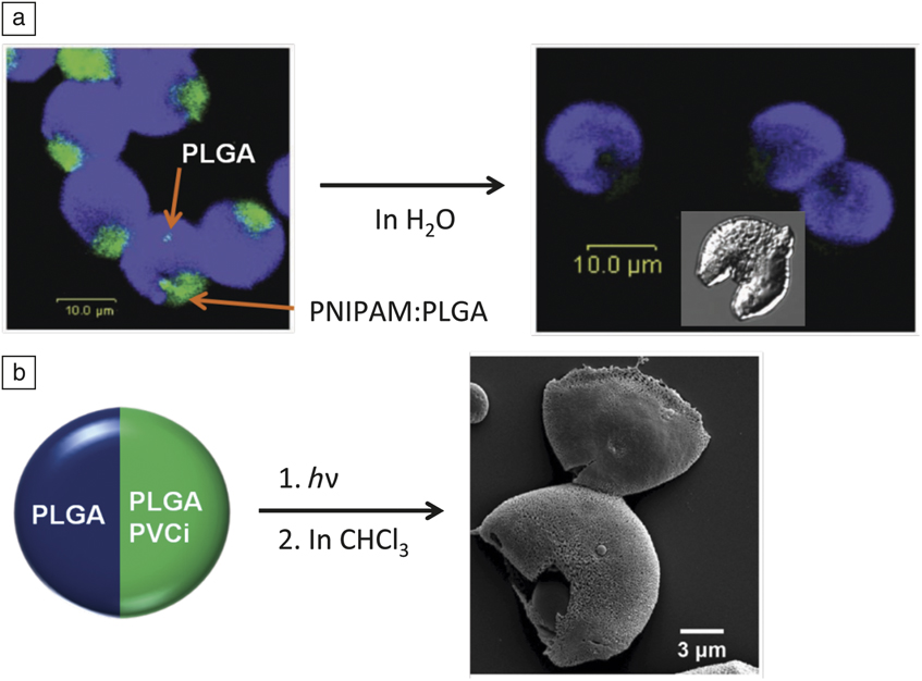
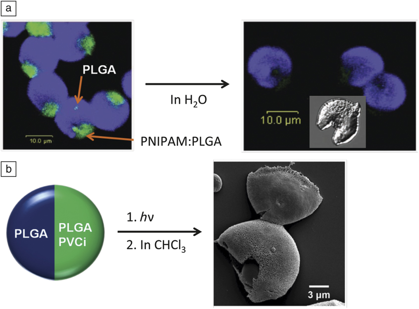
Differential reactivity of individual compartments within a compositionally anisotropic particle provides access to interesting particle architectures that would be otherwise impossible, or at least extremely difficult, to achieve. PLGA microdisks were prepared, which were composed of a quarter compartment containing a mixture of poly(N-isopropyl acrylamide) (PNIPAM) and PLGA. Selective removal of the PNIPAM compartment by exposure to water led to “Pac-Man”-like particles ( Figure 3 ). Reference Bhaskar and Lahann55 Spatially controlled photo-cross-linking reactions of poly(vinyl cinnamate) (PVCi) containing compartments of bicompartmental PLGA microparticles led to novel types of particles with respect to degradation rates, solvent resistance, and mechanical properties. Reference Lee, Hwang, Yoon, Bhaskar, Park and Lahann57 Treatment with chloroform yielded semicapsules manifesting small pores on their surface (Figure 3). Reference Lee, Hwang, Yoon, Bhaskar, Park and Lahann57 Such pores can be used to accelerate the selective degradation, or the release of therapeutics, from one compartment. In addition to being used in biomedical applications such as the selective release of therapeutics, these particles can be used for on-demand self-assembly of anisotropic particles.
(a) A confocal laser scanning microscope image of bicompartmental poly(lactic-co-glycolic acid) (PLGA) microdisks prepared by electrohydrodynamic co-jetting and subsequent microsectioning. The smaller one-quarter compartment (green) comprises a water-soluble polymer (PNIPAM, left), which was selectively removed to yield “Pac-Man”-like particles (right, scale bar: 10.0 μm for both the fluorescent and differential interference contrast images). (b) Porous hemicapsules obtained from spatially controlled photo-cross-linking and subsequent solvent treatment of bicompartmental PLGA particles containing poly(vinyl cinnamate) (PVCi) in one compartment. Reproduced with permission from (a) Reference 55. © 2009 American Chemical Society and (b) Reference 57. © 2011 Wiley. Note: h, Planck’s constant; ν, frequency; PNIPAM, poly(N-isopropyl acrylamide).
Selective surface modification and directional self-assembly
Anisotropic surface modification is one of the simplest methods to prepare Janus particles with different surface patches. The surface properties of these particles can be controlled effectively. Therefore, the selective surface functionalization of compartmentalized particles may offer novel properties, because distinctive functions can be given to external as well as internal design aspects in an independently controllable manner. Adding functionalized polymers into different jetting solutions used in the EHD co-jetting process allows for selective modification of certain parts of the particle. Ultimately, it may even be possible to simultaneously present multiple chemical moieties on parts of the particle surface. In one specific case, the EHD co-jetting of P(AAm-co-AA) solutions was used to incorporate biotin- and acetylene-modified P(AAm-co-AA) in bicompartmental particles. In addition, surface modification of the entire surface area with PEG was necessary to minimize non-specific binding. Selectively functionalized particles had significantly higher binding as compared to PEG-containing particles. Reference Yoshida, Roh, Mandal, Bhaskar, Lim, Nandivada, Deng and Lahann18
In another case, selectively acetylene-functionalized bicompartmental particles were prepared from the EHD co-jetting of PLGA solutions, where one of the solutions further contained poly[lactide-co-propagylglycolide]. Importantly, the addition of the acetylene-modified PLGA did not disturb the co-jetting process. Reference Bhaskar, Roh, Jiang, Baker and Lahann50 The mapping of the vibrational signature via confocal Raman spectromicroscopy confirmed the anisotropic distribution of the acetylene groups. The latter are characterized by a strong Raman band at 2100–2020 cm–1. Finally, the click reaction with azide-PEG-amine confirmed the selective modification of one hemisphere. In spite of the fact that the acetylene-PLGA was incorporated into the bulk, the high uniformity of the fluorescent surface band implied a high number of free acetylene groups on the surface. Reference Bhaskar, Roh, Jiang, Baker and Lahann50 Similarly, spatioselectively modified PLGA particles showed directional self-assembly of bicompartmental particles onto substrates. Reference Bhaskar, Gibson, Yoshida, Nandivada, Deng, Voelcker and Lahann58
Beyond spatioselective bioconjugation, the spatioselective growth of polymer brushes (chains of intertwined polymer strands) on bicompartmental colloidal structures can be used to create new polymer layers or lead to additional compositional anisotropy. Anisotropic, acetylene-modified PLGA microcylinders were prepared by EHD co-jetting and subsequent microsectioning. The incorporation of acetylene-PLGA into one compartment allowed for spatioselective surface modification via copper catalyzed Huisgen heterocycloaddition with an azide-functionalized atom-transfer radical polymerization (ATRP) macroinitiator. Reference Saha, Copic, Bhaskar, Clay, Donini, Hart and Lahann59 The selective growth of hydrogel brushes of oligo(ethylene glycol) methyl ether methacrylate (OEGMA) was achieved by surface-initiated ATRP reactions on the hemisphere of the PLGA microcylinders in the presence of Cu catalyst and OEGMA in water. Confocal micrographs of bicompartmental microcylinders after polymerization had well-defined surface layers composed of swollen PEGMA (poly(ethylene glycol) methyl ether methacrylate). Moreover, the hydrogel compartment causes the microcylinders to bend outward compared to microcylinders prior to ATRP. It was demonstrated that the degree of bending depends on the length of the microcylinders; the curvature generally decreases with cylinder length.
Microsectioning of compartmentalized fibers
The EHD co-jetting process can result in fibers with multiple independent compartments (Figure 2). Because each compartment can be composed of different materials, this technology elegantly provides means of co-locating distinct properties within the same micro- or nanoscale object. This is an attractive feature for designing autonomous materials structures because it allows for the coupled design of different features, such as a sensor and a transducer in close proximity, and transfer of mechanical, electrical, and/or chemical signals via the interface between the components.
Using this approach, anisotropic fibers can be prepared with a wide range of features. We have been able to prepare microfibers with varying composition, number and arrangement of compartments, diameter, and surface chemistry. For instance, Figure 2 shows the results of a recent effort to make fibers with two to seven compartments. The images show not only unprecedented precision in designing different numbers of compartments, but also controllable variation in compartment arrangement. In addition to the PLGA polymer used in this study, we have also extended the technology to a number of different polymers, including PEI and PEG hydrogels. In other recent work, we demonstrated the fabrication of double-cored fibers with three distinct polymers. Reference Lee, Park, Hwang, Yoon and Lahann60 Here, the outermost shell is composed of PLGA, which promotes stable jetting, and the PLGA shell can act as a sacrificial compartment that can be easily removed by washing with dioxane, leading to the free bicompartmental ER/PVCi fiber. Reference Lee, Park, Hwang, Yoon and Lahann60 A particular aspect of the PVCi compartments is that the polymer, and thus the compartments made thereof, can be cross-linked through exposure to UV light.
Anisotropic microcylinders
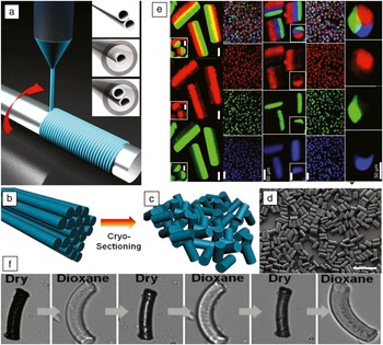
In a straightforward extension of the microfiber work, we were able to create microcylinders with multicompartmental architectures through a semi-automated microsectioning process. Reference Bhaskar, Hitt, Chang and Lahann61 The critical engineering advance was the preparation of perfectly aligned fiber scaffolds. This was achieved by jetting the microfibers on a spinning wheel where the spinning frequency was matched to the jetting velocity. Figure 4 shows examples of different types of microcylinders that were prepared by following this procedure. Variation of the microscectioning amplitude results in multicompartmental microcylinders with different aspect ratios. The improved understanding of the influence of different jetting parameters has allowed for varying the diameter of the microcylinders/microfibers from tens of microns to hundreds of nanometers. The fact that multiple, distinct compartments can be realized within the same microcylinder can give rise to asymmetric properties within the same microcylinder. For instance, two (or more) compartments may have very distinct mechanical properties. In this case, the multicompartmental architecture will be profoundly distinct from a simple blending of the individual polymers. Reference Roh, Martin and Lahann48
Fabrication of bicompartmental fibers and microcylinders based on electrohydrodynamic co-jetting. In (a–d), the fabrication of microcylinders from microfibers is shown: (a) the electrospinning method, types of needles used, and the collecting wheel used for microfiber fabrication; (b–c) the cryosectioning procedure used to process the microfibers into uniformly sized microcylinders; and (d) a scanning electron microscope image of uniformly sized microcylinders fabricated through this process (scale bar is 100 mm). In (e), the top square in each column represents the overlay confocal laser scanning microscope (CLSM) image of the particles, while each subsequent lower square displays the individual CLSM channels representing a single compartment. Scale bars are 10 μm unless otherwise noted; the scale bar in the bottom row of each column is the same for the entire column. (f) Bicompartmental microcylinders composed of a hydrogel/organogel that can undergo reversible, autonomous switching. Microcylinders are about 20 microns in size for imaging reasons but can be prepared with submicron diameters. Reproduced with permission from Reference 61. © 2009 Wiley, and Reference 62. © 2012 National Academy of Sciences.

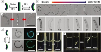
Multicompartmental microcylinders made of conventional polymers can undergo active reconfiguration, such as shape-shifting, reversible switching, or three-way toggling ( Figure 5 ). Once microcylinders with appropriate multicompartmental architectures are prepared by EHD co-jetting, simple exposure to an external stimulus, such as ultrasound or an appropriate solvent, can give rise to interfacial stresses that ultimately cause reversible topographical reconfiguration. The broad versatility of the EHD co-jetting process suggests strategies for a wide range of dynamically reconfigurable adaptive materials, including those with prospective applications for sensors, re-programmable microactuators, or valve structures.
Three-way shape-toggling of bicompartmental microcylinders. (a) Schematic diagram of microcylinders that are composed of compartments containing a hydrogel (green) and an organogel (blue). (b) Optical microscope (OM) images of bicompartmental poly(vinyl cinnamate) (PVCi)/hydrogel microcylinders (sectioned at a length of 50 μm) showing the full range of actuation as indicated by the white dashed arrows, as the solvent environment changes from 100% water to 100% dioxane (left: in water, center: dry state, and right: in dioxane; scale bar: 50 μm). (c) OM (left) and fluorescence OM (right) images of 200 μm microcylinders showing shape-toggling behavior (scale bar: 100 μm). Here, the arrows indicate the same end location on the cylinder and signify the complete inversion of the cylinder in the two solvents. (d) Actuation behavior of a 0.7-mm-long fiber, where the color bar indicates an increasing ratio of water to dioxane (red to blue). (e) OM images of the actuation angles controlled by adjusting the ratios of dioxane and water. The ratios indicate dioxane and water, respectively (scale bar: 50 μm). (f) Photographs displaying shape-toggling of a micromanipulator based on bicompartmental PVCi/hydrogel microfiber segments. (g) Reversible grabbing and release motion of the compartmentalized micromanipulator (grabbing an object by actuation in water and releasing it in dioxane; for comparison, a conventional quartz fluorescence cell (1 cm × 1 cm) has been used to conduct the experiments). Reproduced with permission from Reference 62. © 2012 National Academy of Sciences.

Summary and outlook
While electrospraying and electrospinning can utilize a wide range of polymers, electrohydrodynamic (EHD) co-jetting has so far been accomplished with a limited set of polymers that have similar solution properties. The formation of a stable cone during EHD co-jetting is typically easier to achieve when key solution parameters of the jetting solutions, such as conductivity, viscosity, and density, are similar for the different jetting flows. Beyond the expansion of the EHD co-jetting process to increasingly different sets of polymers, such as water−organic swelling polymers and thermoresponsive/photoresponsive polymers, further modification of the jetting process, including the use of novel needle configurations, different combinations of solvents, and sacrificial templating, may allow for exotic types of multifunctional compartmental particles with dissimilar properties.
Nanometer- and micron-scale control of biodegradable materials is essential for many biomedical applications, including controlled drug delivery, regenerative medicine, or simultaneous imaging and diagnosis applications. The anisotropic surface functionalization of multicompartmental poly(lactic-co-glycolic) acid particles has the potential to satisfy such important criteria.
Acknowledgment
We acknowledge funding from the Multidisciplinary University Research Initiative of the US Department of Defense and the Army Research Office (W911NF-10–1–0518).