Introduction
The efficiency of radio communication in the modern day depends on aerial design. Increased data rate, gain value, and alignment independence may all be obtained with an effective antenna design. A multi-port aerial with circular polarization features can meet these requirements to a great extent. Using diversity technique, multiport aerial may deliver higher data rates without rising signal power [Reference Sharawi1]. The addition of a circular polarization feature may make a transmitter/receiver antenna orientation independent and reduce the fading impact [Reference Sharma, Gupta, Das and Gangwar2]. To enhance the gain, currently, researchers are using ceramic radiators in place of printed radiator due to their inherent ability to no metallic losses [Reference Petosa3]. An aerial parameter refinement is being done using a new idea called machine learning. Many aerial parameter data may be quickly examined via machine learning (ML) approaches [Reference Misilmani, Naous and Khatib4].
Certain research publications about circularly polarized ceramic-based multiport aerials are published in the public domain literature. Two-port dielectric resonator (DR)-based Multi-Input Multi-Output (MIMO) that is triggered by a perturbed circular aperture was invented by Das et al. With the aid of the polarization diversity idea, it operates in the 5.35–5.8 GHz range and achieves isolation levels exceeding 25 dB [Reference Das, Sharma and Gangwar5]. A twin port ceramic circular polarization (CP) radiator designed by Varshney et al. operates between 5.71 and 8.2 GHz and has a 3 dB absorbance ratio between 7.72 and 8.04 GHz [Reference Varshney, Singh, Pandey and Yaduvanshi6]. A two-port rectangle DR-based multiport antenna operating in the 2.36–2.59 GHz range was created by Hu et al. Additionally; it supports CP waves within the 2.39–2.51 GHz working range [Reference Hu, Pan and Yang7]. A polarization translator was created by Reddy et al. and installed above a twin port aerial that was based on DRs. It is compatible with the 5.3–5.51 GHz narrow CP bandwidth [Reference Reddy, Prasad, Dwivedi, Singh, Narayanaswamy and Sharma8]. In a similar way, Abhay et al. structured twin port alumina-based radiator, which operates from 5.25 to 6.17 GHz. With assistance of polarization convertor, it supports CP waves from 5.51 to 6.01 GHz [Reference Yadav, Verma, Penmatsa and Sharma9]. In case of printed antennas, metasurfaces are utilized to enhance the gain as well as to improve the circular polarization bandwidth [Reference Li, Hu, Shi, He, Li, Shang, Zhang, Fu, Zhou, Xiong, Guan, Wang, He and Chen10–Reference Sun, Cai, Yang, Wu, Cheng, Luo, Chen and Li18].
A number of the research publications on aerial interpreting using ML techniques in microwave spectrum can be found. The many ML techniques being used for antenna tuning and performance prediction are intriguing to see. Zheng et al. used a ML tactic to improve a patch aerial with an emphasis on the estimation of |S11| [Reference Zheng, Chen and Huang19]. Sharma et al. use lasso ML, k-nearest neighbour (KNN), and artificial neural network (ANN) for estimating how a T-shaped patch would perform. The performance of these ML algorithms was also evaluated by the writers [Reference Sharma, Zhang and Xin20]. Various ML techniques are used by Ranjan et al. to improve an ultra-wideband (UWB) printed radiator [Reference Ranjan, Maurya, Gupta, Yadav and Sharma21]. In order to forecast the |S11| of a ceramic antenna, Srivastava et al. eliminate disadvantage of ANN with the aid of KBNN [Reference Srivastava, Gupta, Dwivedi, Penmatsa, Ranjan and Sharma22]. An L-formed stimulated ring dielectric multiport aerial was planned by Pandey et al. It receives circular waves in between 2.8 and 3.05 GHz. Several ML methods are applied to enhance the planned radiator [Reference Pandey, Singh and Kumar23].
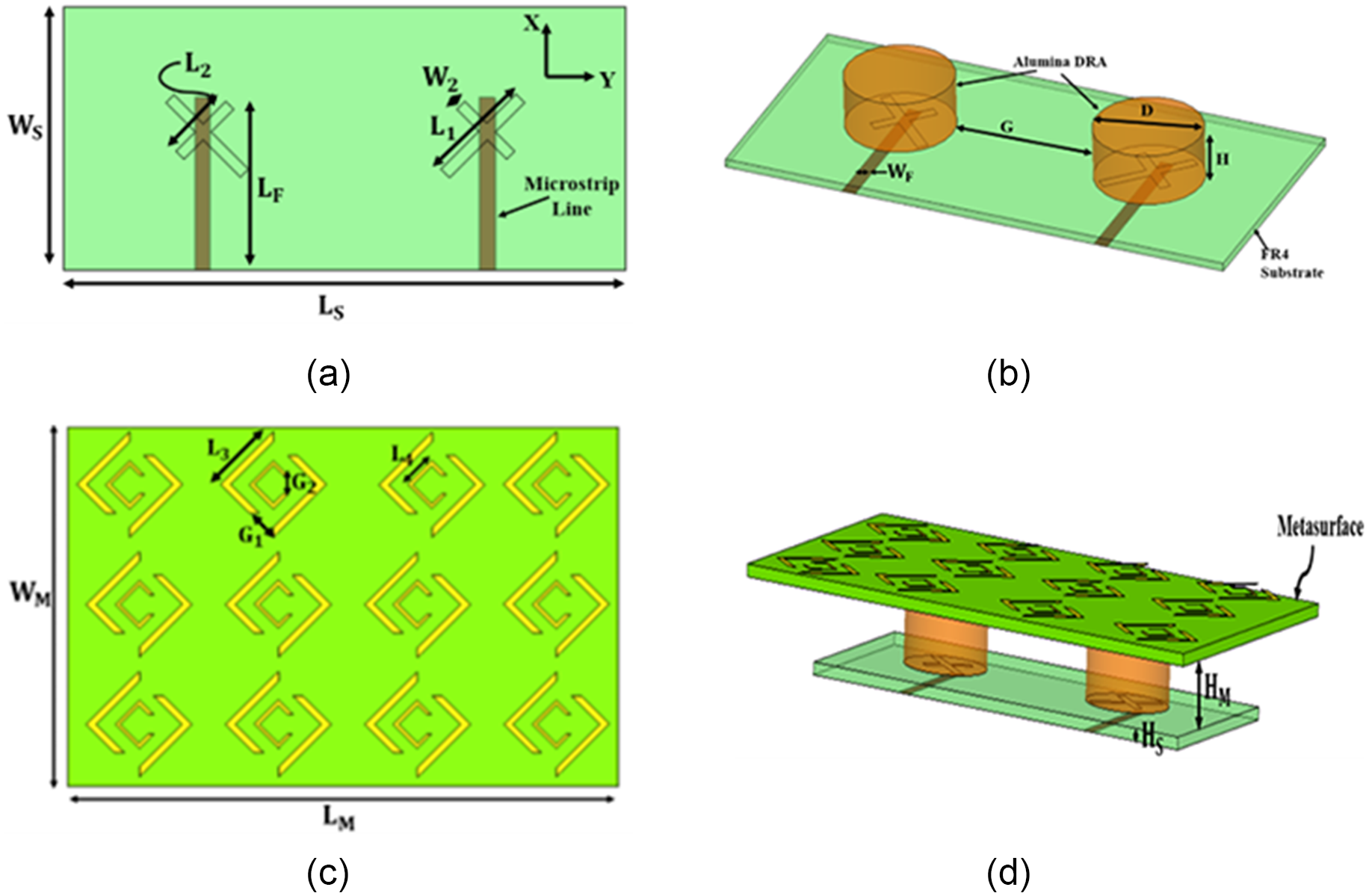
Layout of designed radiator: (a) feed design, (b) ceramic radiator, (c) metasurface design, and (d) 3D view.

This communication provides the detailed investigation of twin port dielectric-based aerial loaded with a metasurface (MS). The uniqueness of this antenna design is to get CP, high isolation (more than 25 dB), and high gain (11.5 dBi) simultaneously without effecting the impedance bandwidth of antenna. Addition of ML-based prediction helps to reduce the computational time required by simulator. However, due to the use of MS, overall size of antenna becomes more. This problem can be overcome by using some other technique of gain enhancement like surface integrated waveguide (SIW). To better understand the concept, this paper is segmented in different sections: (i) structural layout of antenna; (ii) antenna analysis; (iii) prediction of S-parameter using ML algorithms; (iv) experimental authentication; and (v) inference.
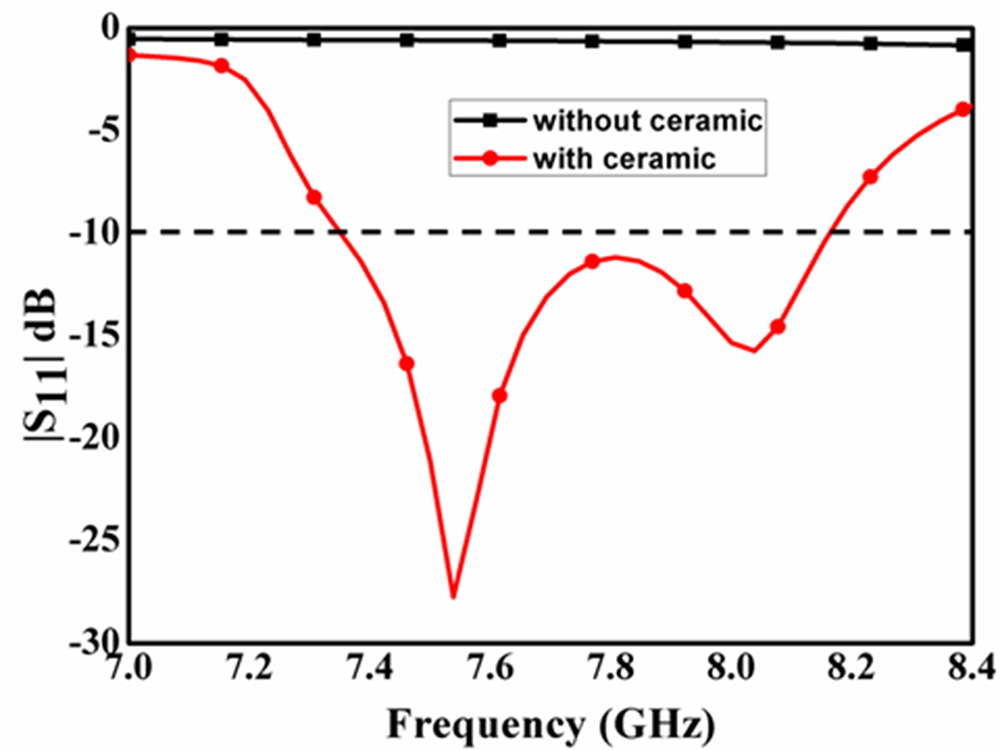
|S11| alteration for one-port radiator with and without ceramic.

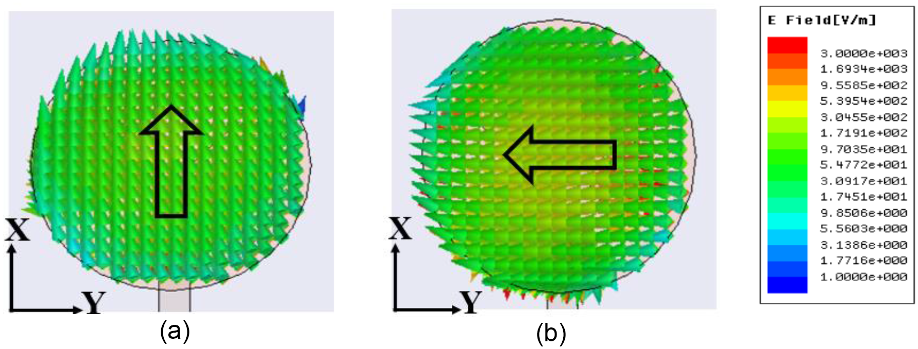
E-field rotation on alumina ceramic (a) 7.58 Ghz (b) 8.1 Ghz.

Structural layout of antenna
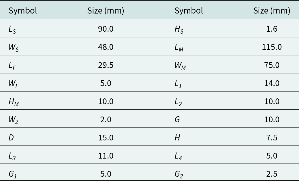
Different views/components of designed two-port aerial are shown in Fig. 1 and the sizes of various parameters of designed aerial is listed in Table 1. Alumina-based ceramic (εr = 9.8) is used as radiator and placed on the FR4 substrate (εr = 4.4). The thickness of substrate is 1.6 mm. Cross-formed slot has been etched from the substrate and created as a feed for ceramic. Printed line is placed in the lower part of substrate and used to feed the cross slot. Metasurface is based on single-sided FR4 substrate with a thickness of 1.6 mm.
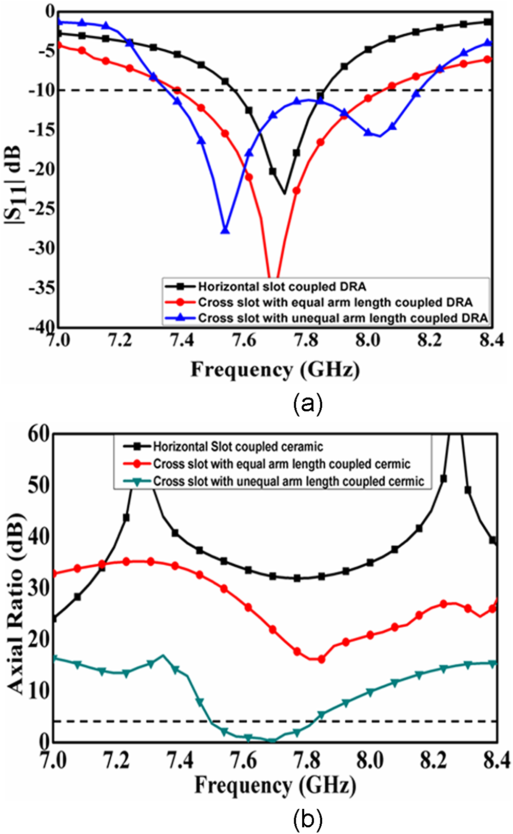
(a) |S11| variation with various alteration in shape of slots and (b) axial ratio variation with various alteration in shape of slots.

Optimal sizes of various parameters of designed aerial

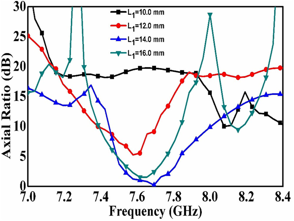
Axial ratio variation with different change in L1.

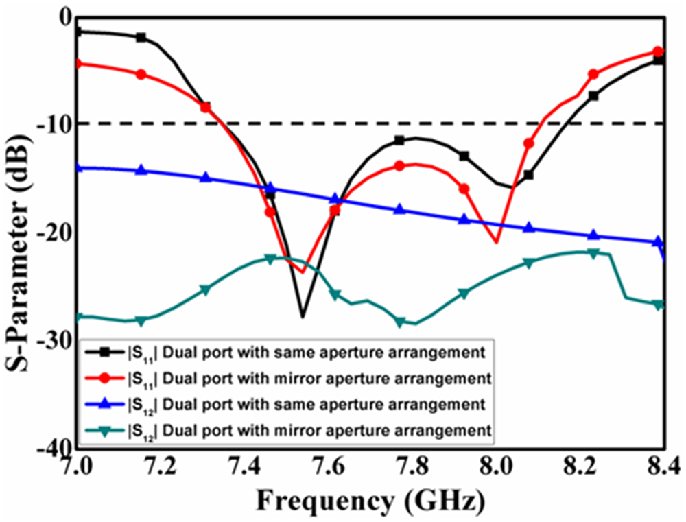
S-parameter alteration for two-port radiator with change in aperture placement.

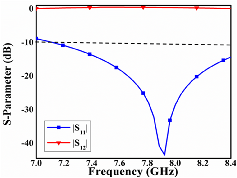
|S11|/|S12| alteration of designed unit cell.

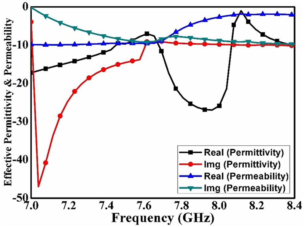
Effective permittivity and permeability of designed unit cell.

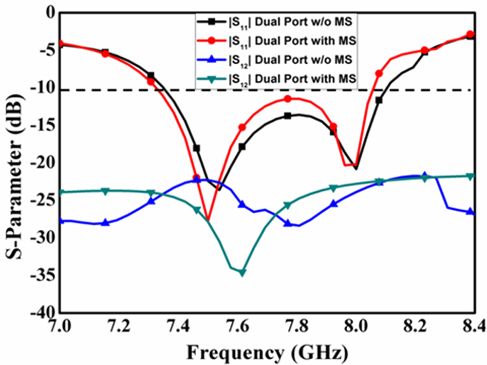
|S11|/|S12| variation of dual port aerial with and without MS.

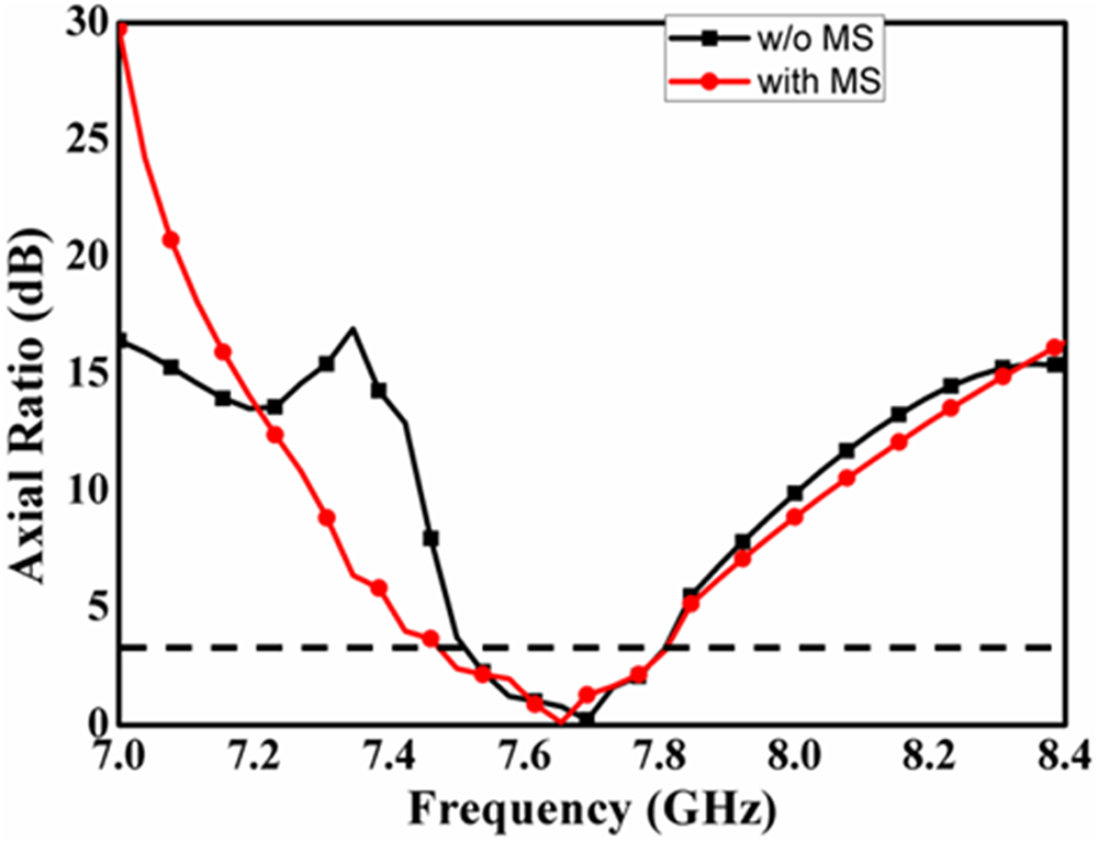
Axial ratio variation of dual port aerial with and without MS.

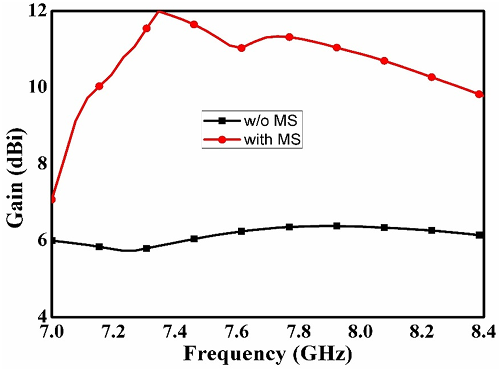
Broadsided gain variation of dual port aerial with and without MS.

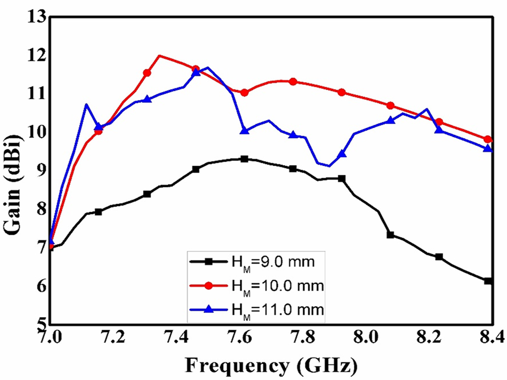
Gain variation with change in HM.

Antenna analysis
This segment provides a detailed investigation on proposed two-port ceramic aerial with the assistance of HFSS software. Analysis has been started with one-port radiator. Figure 2 presents the |S11| alteration for single-port aerial with and without alumina ceramic. One significant reflection found from Fig. 2 that the complete working spectrum is because of alumina ceramic. In the working spectrum, two resonances are visible at 7.58 GHz and 8.1 GHz. Vectored E-field lines are plotted in Fig. 3 at 7.58 GHz and 8.1 GHz. It can be perceived from Fig. 3 that dual orthogonal hybrid mode i.e.  ${\text{HEM}}_{11{{\delta }}}^{\text{x}}$ and
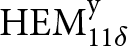 ${\text{HEM}}_{11{{\delta }}}^{\text{y}}$ at 7.58 GHz and 8.1 GHz correspondingly [Reference Kajfez, Glisson and James24]. Numerically, the resonance frequency of fundamental hybrid mode is given as follows [Reference Sharma, Das and Gangwar25]:
 \begin{equation*}{{\text{f}}_{{\text{r}},HE{M_{11\delta }}}} = \frac{{6.321{\text{c}}}}{{{{\pi D}}\sqrt {{{{\varepsilon }}_{\text{r}}} + 2} }}\left[ {0.27 + 0.36\left( {\frac{{\text{D}}}{{4{\text{H}}}}} \right) + 0.02{{\left( {\frac{{\text{D}}}{{4{\text{H}}}}} \right)}^2}} \right]{\text{ }}\left( 1 \right)\end{equation*}
In eqn. (1), ‘“c,” “D,” and “H” denote speed of light, diameter, and height of dielectric rod, respectively. From above equation, the resonant frequency is found to be 7.85 GHz, which is closer to resonance obtained in HFSS software.
For finding out the reason of taking cross slot with unequal arm length, Fig. 4(a) and Fig. 4(b) plot the |S11| and axial ratio alteration with three different cases: (i) rectangular slot linked ceramic; (b) X-slot with identical arm size-linked ceramic; and (iii) X-slot with uneven arm size-linked ceramic. Two significant remarks found from Fig. 4: (a) in case three, two resonant peaks occurred, which is due to orthogonal mode; and (b) X-slot with uneven arm size supports CP waves from 7.42 to 7.8 GHz. A variation in the size of one arm of the X-aperture produces a 90° phase difference between the orthogonal modes, and the cross slot aids in the production of twin orthogonal modes within the DRA. Thus, the suggested aperture provides a dual orthogonal mode inside the ceramic with 90° phase changes, which is a prerequisite for the formation of circular polarization [Reference Balanis26]. Figure 5 presents the axial ratio alteration with change in dimension L1. It can be seen from Fig. 5 that the optimized AR bandwidth is obtained when L1 = 14.0 mm.
Comparing every model using S11 performance metrics

Comparing every model using axial ratio performance metrics

Single port aerial is converted in dual port with parallel placing of antenna ports. However, the aperture orientation is taken as two ways: (i) same slot placement; and (ii) mirror slot placement. Figure 6 shows the alteration of S-parameter with aforementioned two cases. It can be seen from Fig. 6 that |S11| parameter is approx. same in both cases, while the mutual coupling is reduced to less than −25 dB within the working spectrum in case of mirror slot placement. This is because of the polarization diversity concept [Reference Varshney, Singh, Pandey and Yaduvanshi5]. Polarization diversity means that the one port supports left-handed CP (LHCP) wave, while other port supports right-handed CP (RHCP).
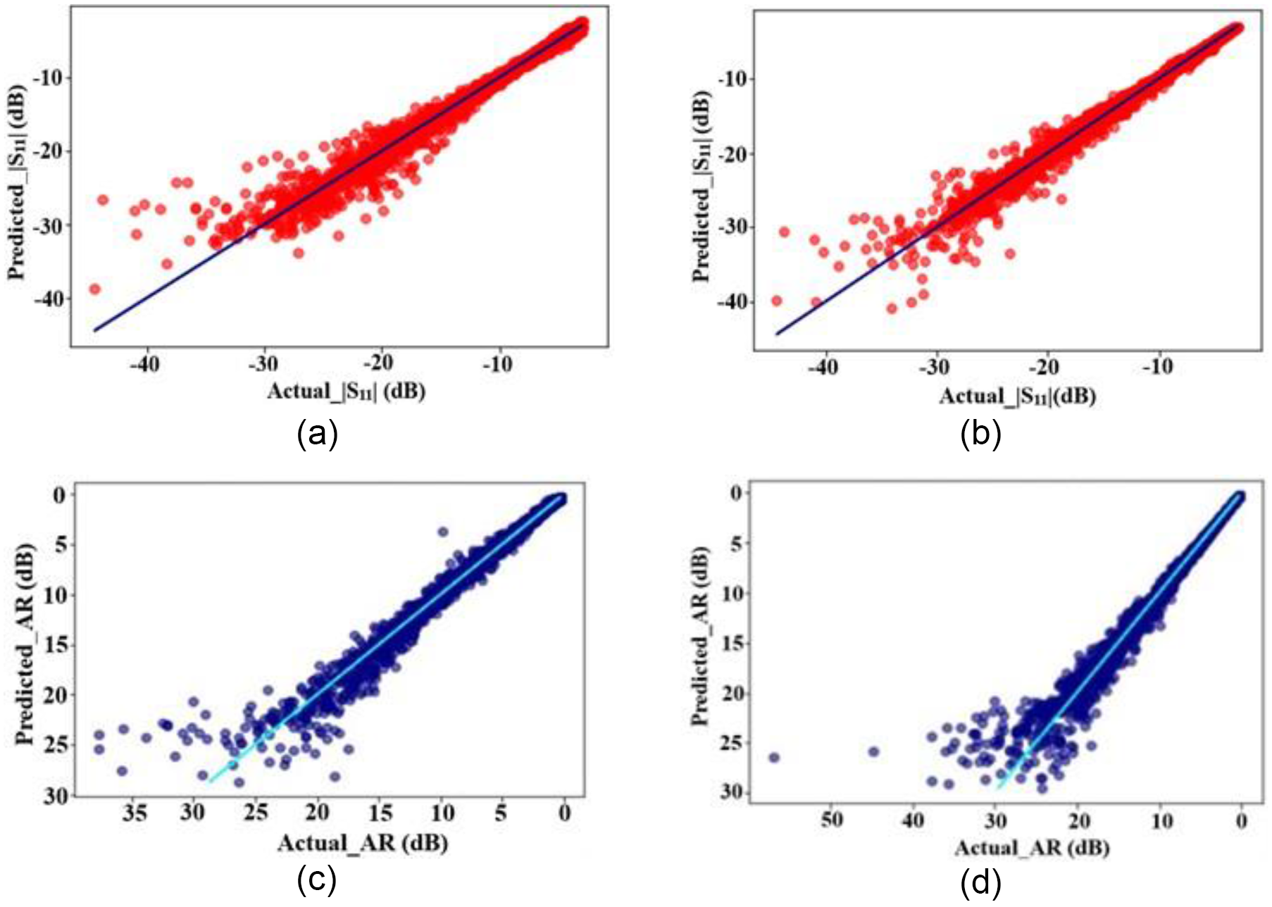
Comparison of the estimated and actual values: (a) decision tree_|s11|, (b) random forest_|s11|, (c) decision tree_axial ratio, and (d) random forest_axial ratio.

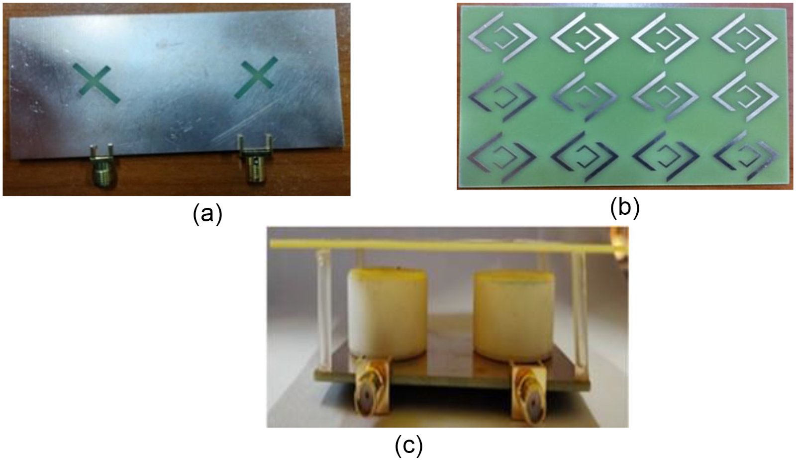
Fabricated prototype of designed aerial (a) feed layout (b) metasurface design (c) adjacent view.

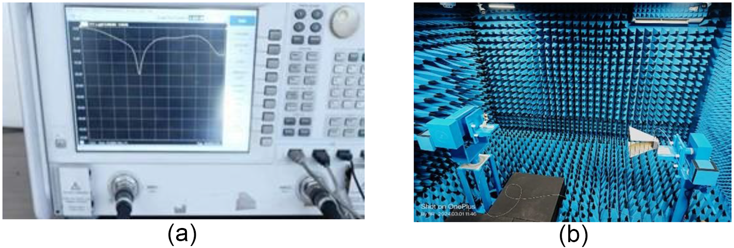
Pictures of measuring setup (a) VNA and (b) anechoic chamber.

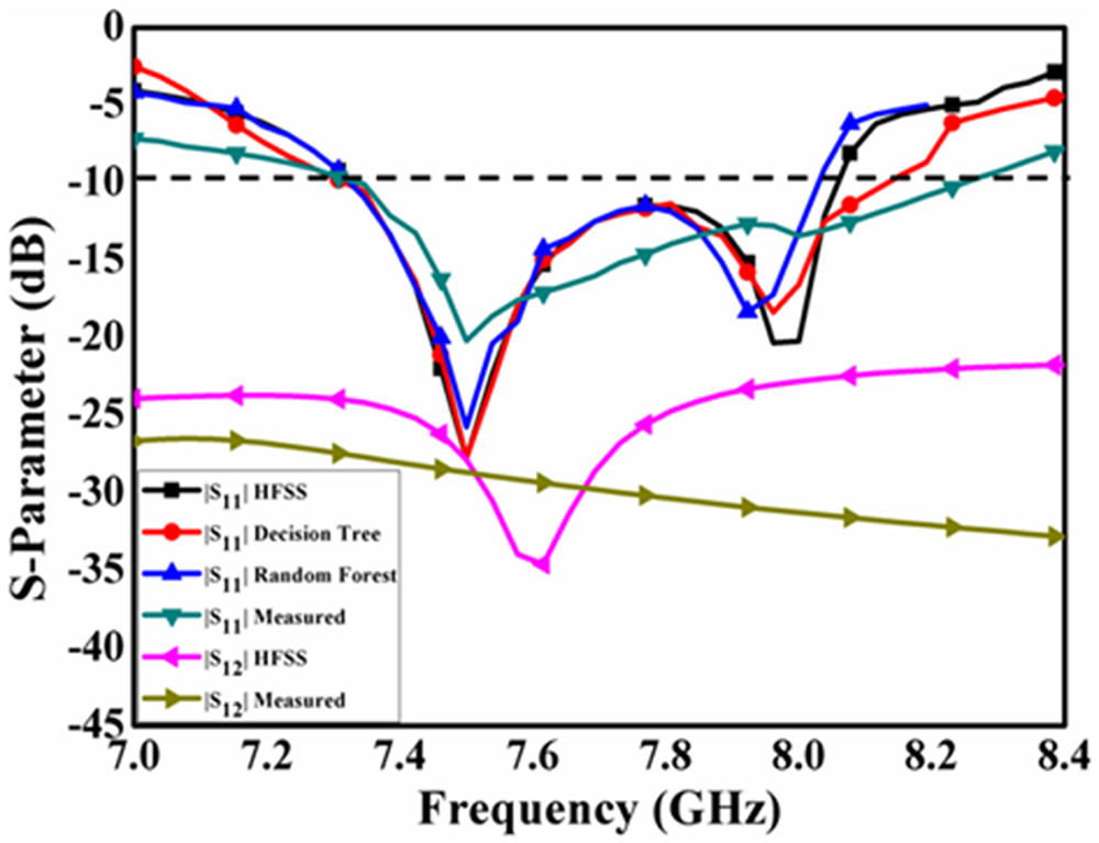
Measured/simulated/forecasted s-parameter of designed aerial.

A MS is suspended over the two-port ceramic radiator. This metasurface is made up of periodic arrangement of unit cell. Figure 7 shows the |S11|/|S12| variation for unit cell. It can be seen from Fig. 7 that |S11| is well below to −10 dB, while |S12| is near to 0 dB with in the working spectrum. This confirms that the unit cell allows the EM waves passes through it. In order to extract the effective dielectric constant and permeability of unit cell, the following equations are utilized [Reference Numan and Sharawi27]:
 \begin{equation}{\text{Z = \pm }}{\left[ {\frac{{{{{\text{(1 + }}{{\text{S}}_{{\text{11}}}}{\text{)}}}^{\text{2}}}{\text{ - S}}_{{\text{21}}}^{\text{2}}}}{{{{{\text{(1 - }}{{\text{S}}_{{\text{11}}}}{\text{)}}}^{\text{2}}}{\text{ - S}}_{{\text{21}}}^{\text{2}}}}} \right]^{{\text{0}}{\text{.5}}}}\end{equation}
 \begin{equation}{e^{j\eta {k_0}d}} = \frac{{{S_{21}}}}{{1 - {S_{11}}\frac{{Z - 1}}{{Z + 1}}}}\end{equation}
 \begin{equation}\varepsilon = \frac{\eta }{Z}{\text{ }}\end{equation}
 \begin{equation}\mu = \eta *Z\end{equation}
In the above equations, “Z,” “d,” “k0,” and “η” indicate the input impedance, width of substrate, wave number, and intrinsic impedance, respectively. “S11” and “S12” denote reflection coefficient and mutual coupling, respectively. “ $ \varepsilon $” and “
 $\mu $” denotes effective permittivity and permeability, respectively. With the assistance of above equations, effective permittivity and permeability is plotted within the working spectrum and shown in Fig. 8. It can be perceived from Fig. 8 that both permeability and permittivity is negative within the working spectrum. This means that unit cell behaves as double negative material.
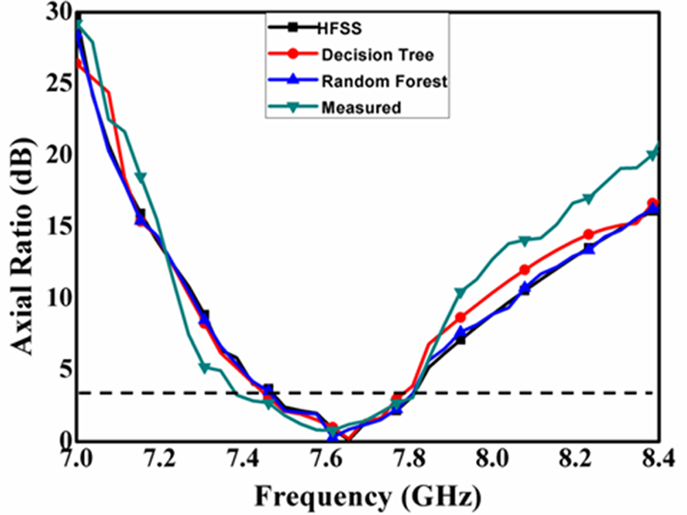
Measured/simulated/forecasted axial ratio alteration of designed aerial.

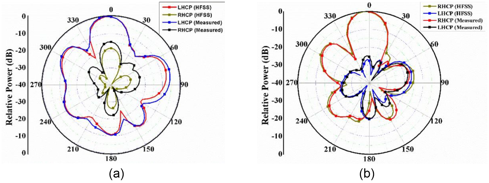
Measured/simulated LHCP and RHCP pattern at 7.6 ghz (a) port-1 (b) port-2.

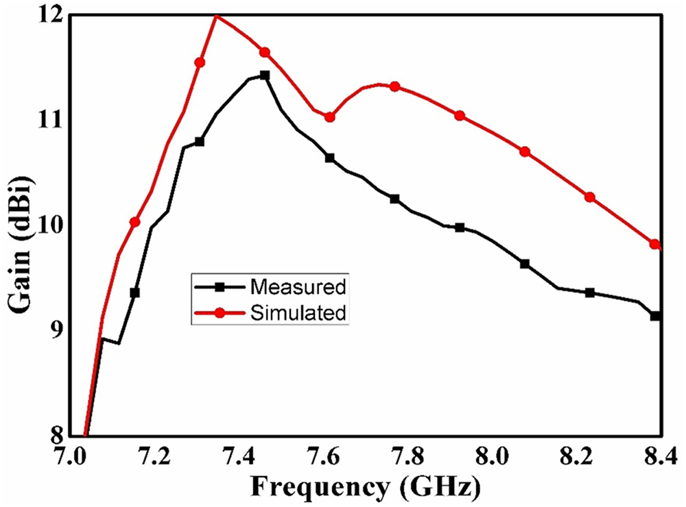
Measured/simulated gain alteration of designed aerial.

Figure 9 presents the S-parameter alteration with and without suspension of MS over the two-port aerial. It can be detected from Fig. 9 that |S11| is approximately same in both circumstances. The mutual coupling level is also same with and without MS. Figure 10 shows the axial ratio variation with and without MS. It is observed from Fig. 10 that the axial ratio curve is also not much effected by placing MS. Broadsided gain variation is shown in Fig. 11 with and without MS. It can be seen from Fig. 11 that the broadsided gain is enhanced to more than 11 dBi after placing MS. Double negative unit cell’s made MS improves the directivity, which in turn improves the antenna’s gain [Reference Samantaray and Bhattacharyya28].
Figure 12 shows the gain variation with different changes in the gap between antenna and MS. It can be seen from Fig. 12 that the optimized gain is obtained at 10.0 mm.
Prediction of s-parameter using ML algorithms
Two different ML methods are applied in this section to predict the planned radiator’s axial ratio and reflection coefficient (S11). Decision Tree and Random Forest (RF), are the ML methods that have been used for that purpose [Reference Ranjan, Maurya, Gupta, Yadav and Sharma21]. A RF voting mechanism selects the main tree as the ultimate output after several trees vote for the outcomes. In ML, decision trees are frequently used to generate and predict results using input data. The architecture resembles a tree, with every inner node testing a property, every branch representing a feature value, and each leaf node representing the ultimate choice or forecast. The main advantage of these two algorithms is to get better accuracy even for smaller data set. After training process, these algorithms are utilized to predict the reflection coefficient and axial ratio value of proposed antenna by simply provides the sizes of various antenna parameters [Reference Bhavani, Raviteja and Shanmuganantham29, Reference Praveena, Umamaheswari, Rai and Ranjan30]. Collections of data are generated by changing D (13.0–17.0 mm in 0.25 incremental step), H (5.0–10.0 mm in 0.25 incremental step), L1 (12.0–16.0 mm in 0.25 incremental step), L2 (8.0–12.0 mm in 0.25 incremental step), HM (8.0–12.0 mm in 0.25 incremental step), LF (27.0–32.0 mm in 0.25 incremental step), L4 (3.0–7.0 mm in 0.25 incremental step), and L3 (10.0–15.0 mm in 0.25 incremental step) with a frequency sweep from 7.0 GHz to 8.4 GHz with 51 points in between the mentioned range after the proposed antenna is designed with the assistance of HFSS. There were 25,041 dataset points in the entire created dataset. Thirty percent (7513) of the complete dataset are utilized for testing, while the remaining seventy percent (17,528) are used for training. A variety of loss parameters features, including as mean squared error (MSE), R-squared loss, and mean absolute error (MAE), are used to assess how well the planned antenna models perform [Reference Ranjan, Maurya, Gupta, Yadav and Sharma21]. Here, the four remaining antenna parameters – D, H, L1, L2, HM, LF, L3, L4, and frequency – are regarded as input features, while S11 and axial ratio are taken as goal variables. Every ML method is trained, and then a validation dataset is used to evaluate every model. All of the outcomes produced by the various ML methods employed for S11 and axial ratio are compared in Tables 2 and 3, respectively. It can be shown from Tables 2 and 3 that random forest has the lowest mean error and the highest R2 Score. Therefore, RF outperforms decision tree in performance prediction.
The anticipated vs. real outcomes graph for RF and Decision Tree on the test dataset for |S11| and axial ratio is shown in Fig. 13. The optimal scenario for regression issues is Y = X. Therefore, a higher density in the vicinity of the Y = X line indicates superior algorithmic performance. It can be shown from Fig. 13 that the random forest forecast is more accurate. For larger negative values of |S11|, the predicted value differed further from the real one.
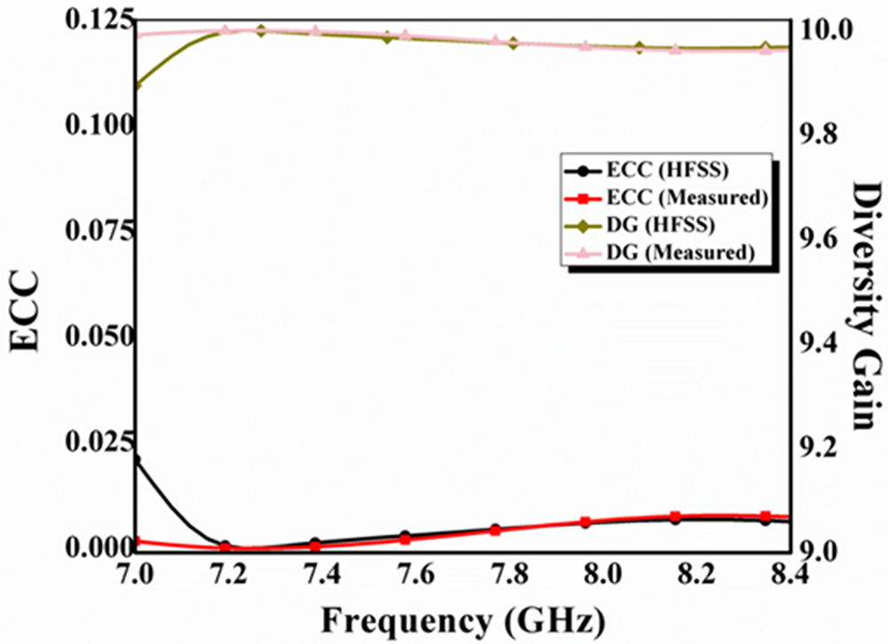
ECC and DG alteration of planned aerial.

Experimental verification
This section focuses on validating optimized simulated/forecasted machine learning outcomes with empirically acquired results. The designed aerial prototype is made and evaluated for this reason. In Fig. 14, it is displayed. Figure 15 shows the pictures of measuring set up i.e. vector network analyser (VNA) and anechoic chamber. Keysight’s E5071C VNA is used to measure the S-parameter. The frequency range for Anechoic Chamber is from 1 to 18 GHz. The designed aerial’s simulated, predicted, and measured S-parameter is shown in Fig. 16. There is good agreement among forecasted, simulated, and practically obtained S-parameter. The designed aerial works effectively in 7.21–8.2 GHz with the separation level more than 25 dB. Slight variance is obtained owing to the influence adhesive substance for adhering the ceramic over substrate. Addition of adhesive creates the small air gap between alumina ceramic and substrate. Due to this, there is reduction in impedance matching as well as shifting in the resonance peak [Reference Faiz, Gogosh, Khan and Shafique31].
Figure 17 presents the comparison of simulated/forecasted and experimentally attained axial ratio alteration for designed aerial. It is measured inside the anechoic chamber with the technique of dual linear far-field measurement [Reference Stutzman and Thiele32]. It can be seen from Fig. 17 that there is good correlation among simulated, forecasted, and experimentally gained axial ratio. The designed aerial supports CP waves in between 7.35 and 7.8 GHz. Figure 18 shows the 2D measured/simulated LHCP and RHCP pattern at 7.6 GHz. Good corelation is obtained between experimental and simulated LHCP and RHCP pattern. In case of port-1, the LHCP is more dominant as compare to RHCP. That means, the port-1 supports LHCP waves from ceramic. Similarly, port-2 supports RHCP waves. Because of this, polarization diversity concept is supported by designed aerial. Broadsided far-field confirms the HEM11δ mode inside the ceramic material. Figure 19 presents the experimental and simulated gain alteration of designed aerial. It is measured using two antenna technique [Reference Stutzman and Thiele32]. Due to directive pattern, the maximum gain of designed aerial is approx. 11.5 dBi.
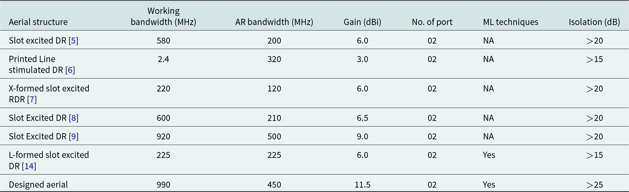
Table 4 compares the performance of designed aerial with published two-port aerials on the basis of working range, aerial’s gain and utilization of ML technique. The designed aerial provides wider impedance as well as axial ratio bandwidth. Aerial gain and isolation level between the ports of designed radiator is also quite high in comparison to published radiator. Last and important analysis for designed aerial is MIMO parameters, i.e. Envelop Correlation Coefficient (ECC) and diversity gain (DG). ECC talks about likeness among the antenna ports. It should be as low as (less than 0.2) possible for effective multi-port aerial. DG is directly related to ECC and talks about multi-port gain in fading situation [Reference Sharawi1]. There are well known formulas for calculating ECC and DG [Reference Sharawi1]. Figure 20 presents the simulated and experimental ECC and DG alteration for designed aerial. It can be seen from Fig. 20 that EEC is much lower than the standard, i.e. 0.2, while DG is approx. 10.0 within the working spectrum. This confirms the effectiveness of designed multi-port ceramic aerial.
Comparing the designed twin band aerial’s performance to published CP multiport ceramic aerials

Conclusion
A two-port ceramic-built aerial has been designed and examined in this communication. Some functioning factors such as, reflection coefficient and mutual coupling has also been predicted using Decision Tree and RF-based ML techniques. A metasurface made of double negative unit cells has been suspended over the twin port aerial for getting high gain, i.e. around 11.5 dBi. Cross slot with imbalanced arm size aids to produce circular waves in between 7.35 and 7.8 GHz. This antenna supports LHCP with port-1 and RHCP with port-2, which expands the separation level to 25 dB. With the help of fundamental hybrid modes, the designed aerial works in between 7.21 and 8.2 GHz. The major problem associated with the designed antenna is its bulky size due to the presence of MS. The aerial will work for deployment in 6G communication networks due to all these capabilities.
Funding statement
This research received no specific grant from any funding agency, commercial or not-for-profit sectors.
Competing interests
The authors report no conflict of interest.

Swati Anand Dwivedi received her B.E., M.E. Degree in Electronic and Communication from Rajiv Gandhi Technical University (Govt.), India. She is pursuing Ph.D. from Amity University Gwalior. She has more than 5 years of teaching and administrative experience.

Raghavendra Sharma completed his B. Tech. in Electrical Engineering from Dayalbagh Educational Institute (Deemed University) Agra, M.Tech in Electronic Design & Technology from Central Government Institute CEDTI Aurangabad (MS) and Ph.D. from Dayalbagh Educational Institute (Deemed University) Agra in the area of Signal Processing. In his teaching and research career of more than 25 years he has published more than 60 research papers in various Journals and Conferences of International & National repute (Scopus/SCI) and he is the editor of ETJRI (ISSN: 2581-8678) run by Amity University Madhya Pradesh Gwalior. He is Fellow of IETE and member of IEI, IETI (USA), IET, etc. He has filed more than 15 patents. He has guided more than 20 PG & PhD students, and his research interest lies in Digital Signal Processing, Image Processing, VLSI Design, Antenna Design, and Soft Computing.

Vivek Singh Kushwah (SMIEEE) received his B.E., M. Tech., and Ph.D. degree in Electronics & Communication Engineering from Rajiv Gandhi Technical University (Govt.), India. Presently, he is working as a Professor in Electronics and Communication Engineering Department at Chaitanya Bharathi Institute of Technology (A), Hyderabad, India. He has more than 17 years of teaching, research, and administrative experience. His research areas of interest include Artificial Neural Networks, Microstrip Antenna, R.F. and Microwave Filters, etc. He is associated with many SCI Journals and IEEE international conferences around the world as committee member, Reviewer and session chair. Presently, 4 Research Scholars are pursuing Ph.D. under his guidance and awarded 5 PhD Degrees, 92 B. Tech., and 1 M. Tech. Degree under his supervision. He evaluated 5 PhD Thesis. He received the “International Researcher Award 2020-21” and received “Dainik Bhaskar Teachers Excellence Awards 2022”.