1. INTRODUCTION
Processing of coatings/films deposited on the given substrate is nowadays a subject of great interest primarily due to applicative reasons. The interest for processing is wide – from mechanical engineering, optical industry all the way to micro- and nano-electronics (Badi et al., Reference Badi, Tempez, Starikov, Bensaoula, Ageev, Karabutov, Ugarov, Frolov, Loubnin, Waters and Shultz1999; Bobzin et al., Reference Bobzin, Bagcivan, Ewering, Gillner, Beckemper, Hartmann and Theiss2011; Brecher, Reference Brecher2012). Modification of coatings is a complex procedure that requires, among other things, adjustment of the processing depth so that it does not surpass the coating depth. In this context, it is important to choose modification parameters. Laser modification of the coatings surface is the method of choice, often the only one efficient, since it enables: (a) Structuring of hard coatings with the appropriate radiation intensity; (b) highly-precise structuring (excellent control of the ablated surface); (c) non-contact procedure, etc.
a-CN/TiAlN double layer coating on ASP30 steel, which is the subject of this work, is a relatively new coating combination and due to its excellent properties it can be applied for numerous applications, for example, industry (protection of cutting tools for dry machining) and sensor technology (Derflinger et al., Reference Derflinger, Brandle and Zimmermann1999; Paskvale et al., Reference Paskvale, Kahn, Cekada and Panjan2009; Panjan et al., Reference Panjan, Paskvale, Fisinger, Mernik, Panjan, Cekada and Kek-Merl2011a; Reference Panjan, Paskvale, Gselman, Zupanič, Bončina, Čekada, Panjan, Kek-Merl and Fišinger2011b). Generally, this type of technology provides strong ecological and economic gain. The double layer coating is composed of TiAlN base layer (in contact with the steel substrate) and carbon-based top layer (a-CN), achieving the combination of high hardness and thermal stability of TiAlN layer (providing effective wear protection) with sliding and lubricating properties of the top carbon based layer (allowing smooth chip flow). Some specific applications (Paskvale et al., Reference Paskvale, Kahn, Cekada and Panjan2009; Panjan et al., Reference Panjan, Paskvale, Gselman, Zupanič, Bončina, Čekada, Panjan, Kek-Merl and Fišinger2011b) require that the top carbon based layer possesses better elasticity, which is why the nitrogen is added making amorphous carbon nitride (a-CN) (Panjan et al., Reference Panjan, Paskvale, Gselman, Zupanič, Bončina, Čekada, Panjan, Kek-Merl and Fišinger2011b). Also, the benefit of incorporating nitrogen can be the increase of surface energy providing higher wettability, important for some applications. One of the applications of carbon-based and TiAlN coatings is for the surfaces of plastic injection moulds which have to be resistant to wear and melt adhesion. In the case of complicated parts with certain microstructural shapes, one-step industrial production is a problem due to the difficulty in obtaining a negative pattern. Ultra-short laser processing can be one of the possible solutions for this purpose.
a-CN/TiAlN double layer coating on ASP30 steel irradiated with laser radiation was not discussed in literature, unlike multilayered coatings of TiAlN/TiN (Gakovic et al., Reference Gakovic, Radu, Zamfirescu, Radak, Trtica, Petrovic, Panjan, Zupanic, Ristocu and Mihailescu2011) and single a-CN (Forster et al., Reference Forster, Egerhazi, Haselberger, Huber and Kautek2011). Although, it should be pointed out that even the studies of laser texturing of single coatings are still scarce. The present paper deals with the effects of pulsed energetic Ti: Sapphire femtosecond (fs) laser emitting in the near infrared region on a-CN/TiAlN double layer coating deposited on ASP30 steel. Special attention was paid to surface changes of the target depending on laser energy. Also, chemical surface variations in the interaction zones were monitored. The studies were carried out in the regime of laser power densities of 1013 and 1014 W/cm2.
2. EXPERIMENTAL
The target used in the experiments was a-CN/TiAlN double layer coating deposited on high quality steel as a substrate. Substrate was in the form of disc (made of powder metallurgy tool steel ASP30) with 20 mm diameter and 3 mm thickness. Two coating layers had total thickness (t) of 4.8 μm. The first layer directly attached to the substrate was TiAlN (t 1 = 4.2 µm) and the second one at the top was a-CN (t 2 = 0.6 µm). Prior to coatings deposition, the steel substrate was prepared by standard metallography procedure that consisted of grinding, polishing (with diamond paste up to surface roughness of ~0.025 µm), ultrasonic cleaning, solvent/water rinsing, and finally drying in hot air.
All coatings were prepared in a CC800/9 sinOx ML industrial deposition system manufactured by CemeCon (Germany). The system is equipped with four rectangular magnetron sputtering cathodes facing the table holder. The sources were arranged in the corners of a rectangle. Rotating table has five substrate holders which rotate with double rotation. Three cathodes were used for deposition of TiAlN and only one for deposition of a-CNx layer. Target materials were TiAl and pyrolytic graphite (purity 99.8%). In the deposition chamber substrates were heated to 400°C for 60 min. After that they were cleaned by ion etching for 30 min (pulsed; 240 kHz; 650 V). In the first part, three cathodes with segmental TiAl targets with approximately 1:1 Ti to Al ratio were active for depositing TiAlN. The flow rate of N2 was 170 sccm and the power on each of the TiAl targets was 9.5 kW. In the second part, one graphite target was active with the power of 4 kW and N2 flow of 70 sccm. The process pressure during deposition was constant at around 0.4 Pa. Thickness ratio of TiAlN to a-CNx was ~7:1
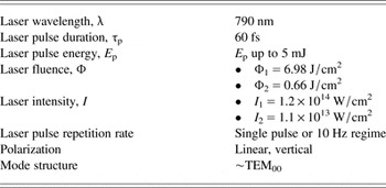
Laser irradiation experimental setup was similar to the one given in reference by Trtica et al. (Reference Trtica, Batani, Redaelli, Limpouch, Kmetik, Ciganovic, Stasic, Gakovic and Momcilovic2013). Laser beam with diameter of 15 mm was focused normally on the target by a 150 mm focal length lens. During the irradiation process, laser was operated in the near fundamental transverse mode TEM00. Irradiations were carried out in vacuum (~0.001 mbar) environment. The employed Ti: Sapphire fs laser system was PULSAR by Amplitude Technologies, based on chirped pulse amplification. Central laser wavelength is approximately 790 nm, maximum laser energy 12 mJ, and minimum laser spot diameter after focusing 50 µm (spot diameter in the experiments was typically ~300 µm). The sample (a-CN/TiAlN-steel ASP30) was mounted on a four axis (x, y, z, and θ) motorized computer-controlled positioning system, so that the fresh target surface could be exposed to laser beam before each series of shots. Typical laser output parameters with experimental conditions are presented in Table 1.
Typical parameters of fs Ti: Sapphire laser used for irradiation of the sample (a-CN/TiAlN deposited on ASP30 steel).

Various analytical techniques were used for characterization of the sample before and after laser irradiation. Surface morphology was monitored by optical and scanning electron microscope (SEM), which was used in secondary and back scattering electron mode. SEM was connected to an energy dispersive analyzer (EDS) for surface compositional analysis of the target. Compositional depth profiles were obtained by glow-discharge optical emission spectrometry (GDOES). Profilometric analysis was used for specifying the geometry of the ablated area.
3. RESULTS AND DISCUSSION
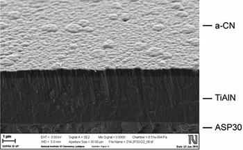
Fracture cross-section of a double layer coating a-CN/TiAlN deposited on polished powder metallurgy tool steel ASP30 substrate, is shown in Figure 1. Next to the substrate, as it was mentioned, is the TiAlN hard layer, while the top layer is a low-friction carbon based layer (a-CN). TiAlN layer had a dense columnar structure (Fig. 1), while a-CN had amorphous form.
SEM image of a fracture cross-section of a-CN/TiAlN double layer coating deposited on ASP30 steel substrate. The image was made under an angle (thicknesses of TiAlN and a-CN layer were 4.2 and 0.6 µm, respectively).

Elemental compositional depth profiles, as-deposited, were obtained by using a GDOES analysis. Depth analysis has shown the presence of elements such as C, N, Ti, Al, and Fe. The concentration of carbon is relatively high at the depth of approximately 0.6 µm, corresponding to the a-CN layer thickness. After this depth, Ti and Al concentrations had high values up to ~4.6 µm, corresponding roughly to the sum of both layer thicknesses. After the depth of ~5.0 µm concentrations of Fe and Cr2 (constituents of the ASP30 steel) increase, it implies that the substrate is reached. The above analysis confirms that layer thicknesses are in accordance with the projected values.
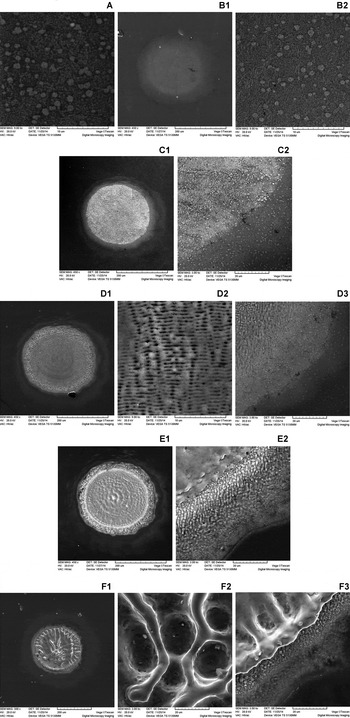
Non-irradiated surface of the target, a-CN/TiAlN coatings on ASP30 steel, typically black-gray colored, had roughness of less than 0.05 µm, as obtained by profilometer. Generally, surface modification of the target depends on the laser output parameters – pulse energy density (fluence), intensity, wavelength, laser pulse duration, number of accumulated laser pulses, as well as the sample characteristics, for example absorptivity, and environmental conditions such as working atmosphere (vacuum, air, etc.). Morphological changes on the a-CN/TiAlN-ASP30 steel target as a function of accumulated laser pulses (1, 5, 10, 50, and 100 pulses) are shown in Figures 2–6. Figures 2 and 6 represent the modified surface of the sample at higher and reduced laser fluence, respectively. The induced features are presented in more details below.
SEM analysis of the a-CN/TiAlN coating deposited on ASP30 steel substrate surface after irradiation with fs laser pulses. Vacuum atmosphere; I 1 = 1.2 × 10¹⁴ W/cm2 (Φ1 = 6.98 J/cm2). A – view of the target before irradiation. B, C, D, E, F – after irradiation with 1, 5, 10, 50, and 100 pulses. (B1, C1, D1, E1, F1 – entire spot; B2, D2, F2 – central area and C2, D3, E2, F3 – periphery).

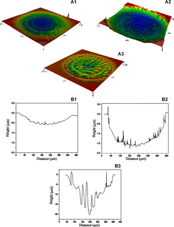
Profilometric analysis. 3D-(A) and 2D-view (B) of the damages and their cross-section after laser irradiation of a-CN/TiAlN coating deposited on ASP30 steel substrate. Vacuum atmosphere; I 1 = 1.2 × 10¹⁴ W/cm2 (Φ1 = 6.98 J/cm2). (A1) and (B1), (A2) and (B2), (A3) and (B3) – after irradiation with 1, 10, and 100 pulses.

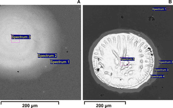
SEM images of the a-CN/TiAlN coating deposited on ASP30 steel substrate with labeled locations for EDS analysis. I 1 = 1.2 × 10¹⁴ W/cm2 (Φ1 = 6.98 J/cm2). (A) After 1 pulse (spectra 1 and 2 – damage rim, that is, further and near periphery; spectrum 3 – damage center); (B) After 100 pulses (spectrum 1 – non-irradiated region; spectra 2, 3, and 4 – periphery region and spectrum 5 – central damage zone).

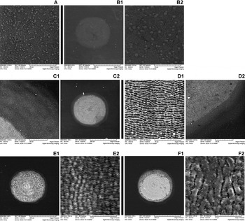
SEM analysis of the a-CN/TiAlN-ASP30 steel sample surface after irradiation with fs laser at reduced intensity and different number of pulses. Vacuum atmosphere; I 2 = 1.1 × 10¹³ W/cm2 (Φ2 = 0.66 J/cm2). B, C, D, E, F – after irradiation with 1, 5, 10, 50, and 100 pulses. A – view of the target before irradiation. (B1, C2, E1, F1 – entire spot; B2, D1, E2, F2 – central zone and C1, D2 – periphery).

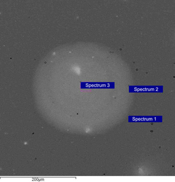
SEM images of the a-CN/TiAlN-ASP30 steel sample with labeled locations of EDS analysis after 1 pulse. I 2 = 1.1 × 10¹³ W/cm2 (Φ2 = 0.66 J/cm2). (Spectra 1 and 2 – damage rim, that is, further and near periphery; spectrum 3 – damage center).

3.1. Regime of Higher Laser Intensity
Initially, the effects of fs laser on the sample were studied at higher laser intensity. This intensity was achieved on the sample surface by focused laser beam with single pulse energy ~5 mJ and the corresponding fluence (Φ1) ~7 J/cm2. Equivalent laser intensity I 1 was ~1.2 × 10¹⁴ W/cm2 (Table 1). The view of the double layer coating surface before and after irradiation is shown in Figure 2. Surface changes can be summarized as follows: (a) For 1, 5, and 10 pulses (Figure 2 B, C, D) one or both layers were preserved, which was confirmed by compositional analysis using SEM in back scattering mode operation, as well as EDS. Action of 1, 5, and 10 pulses does not change the surface composition even though morphology alterations clearly occur. Comparing central area upon 1 laser pulse, Figure 2B2, with non-irradiated region, Figure 2A, it can be concluded that the grain structure is present while the size of the grains is diverse. Irradiation with 5 and 10 pulses, Figure 2C and D, resulted in the formation of ripples, that is, laser induced periodic surface structures (LIPSS) covering the entire spot. The spacing between two successive ripples (periodicity) in the central as well as peripheral irradiated region was ~700 nm (Fig. 2C and D), almost in accordance with the laser wavelength used (790 nm). Maintaining of one or both layers was also confirmed by profilometry measurements, Figure 3A1, B1 and A2, B2. One pulse resulted in coating removal up to 0.5 µm in depth, while 10 pulses caused a 1.6 µm thickness decrease compared with the initial. This implies that, after 1 laser pulse top layer (a-CN) is still present but with reduced thickness. On the other hand, 10 pulses caused the total removal of a-CN layer and partial removal of TiAlN layer, Figure 3A2, B2; (b) Crater like damages, Figures 2E and F, are prominent for 50 and 100 pulses. Crater depths were ~5 and ~20 µm, respectively. In the central part of interaction double layer coating was completely removed and only melted substrate material with local cavities is present. Appearance of these cavities (Fig. 2F1, 2) was registered in various materials and their generation can be attributed to very high temperature and phase explosion phenomenon (Craciun & Craciun, Reference Craciun and Craciun1999); (c) Creation of sharp rims surrounding the craters, especially prominent at 50 and 100 pulses, Figure 3A3 (given only for 100 pulses). Irradiations under these conditions were always accompanied by plasma formation.
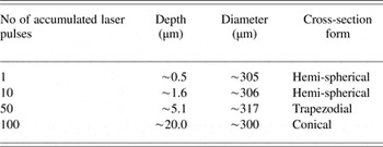
Depth and diameter of the damage, Table 2 and Figure 3, increased up to 100 accumulated laser pulses. Simultaneously, the presence of some ablated material in the interaction region (100 pulses) probably caused the total damage depth to be greater. Cross-section of the damages, Table 2 and Figure 3, also changed with the laser pulse number, varying from semi-spherical to close conical form (Fig. 3B1–B3). The conical shape can be correlated with intensive processes which take place in the interaction region, particularly with the occurrence of phase explosion (Karnakis, Reference Karnakis2006). Similar form of the crater cross-section on laser irradiated materials was also observed in several other references (Yoo et al., Reference Yoo, Jeong, Greif and Russo2000; Karnakis, Reference Karnakis2006). Highest depth was achieved in the central part of the damage corresponding to the spatial profile of laser beam, that is, TEM00 operation mode.
Damage parameters (depth, diameter, and cross-section) as a function of laser pulse count.

By comparing our results with the results obtained on TiAlN layer (top TiAlN layer thickness 0.5 µm, total multilayer thickness 2.2 µm; steel substrate) (Gakovic et al., Reference Gakovic, Radu, Zamfirescu, Radak, Trtica, Petrovic, Panjan, Zupanic, Ristocu and Mihailescu2011) we can state that the a-CN layer can be ablated more easily – 0.5 µm after 1 pulse (0.1 µm remaining), while in the case of TiAlN about 100 nm is removed. It is an expected result due to higher hardness of TiAlN. This implies that for the micro-structuring of a-CN layer, milder fluences need to be employed. After 5–10 accumulated laser pulses, LIPSS occurred over the entire spot, with the periodicity of ~700 nm, similar to reference by Gakovic et al. (Reference Gakovic, Radu, Zamfirescu, Radak, Trtica, Petrovic, Panjan, Zupanic, Ristocu and Mihailescu2011). After 10 pulses, around 1.6 µm is removed and TiAlN layer is still preserved. For 50 applied pulses ablated depth is 5.1 µm which means that the steel substrate is reached. Regarding the morphology, laser spot in our study is more defined and circularly shaped, while in (Gakovic et al., Reference Gakovic, Radu, Zamfirescu, Radak, Trtica, Petrovic, Panjan, Zupanic, Ristocu and Mihailescu2011) it is irregular with visible material re-deposition on further periphery.
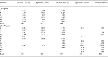
Irradiation of a-CN/TiAlN coating deposited on ASP30 steel substrate was conducted in vacuum (~0.001 mbar). EDS surface elemental analysis obtained from non-irradiated and irradiated locations (Fig. 4) is given in Table 3. EDS analysis was, in one hand, employed for relative comparison of the presence of elements on treated and non-treated surface.
Local EDS elemental analysis of irradiated and non-irradiated locations*.

* Measuring locations are given in Figure 4 (A) 1 laser pulse (spectra 1 and 2 – damage rim; spectrum 3 – damage center); (B) 100 laser pulses (spectrum 1 – non-irradiated region; spectra 2, 3, and 4 – periphery region and spectrum 5 – central damage zone).
Non-irradiated surface analysis (Fig. 4B – spectrum 1 and Table 3 – spectrum 1), aside from the elements of top layer (C, N) and elements of the lower layer (Ti, Al, N), shows also the main element of the ASP30 steel substrate – Fe. This elemental content can be primarily explained by the relatively high energy of electrons penetrating to a depth of several microns, which is higher than the total thickness of double layer coating (4.8 µm). Oxygen is also present in the EDS spectra and it originates probably from the sample exposure to an air ambient. Irradiation of the surface with 1 laser pulse, Figure 4A and Table 3, caused changes in the elemental composition from periphery to the central zone. Profilometric analysis, Figure 3A1, B1, showed that upon 1 pulse only 0.5 µm of the first a-CN layer thickness was removed thus its integrity is still preserved (a-CN thickness = 0.6 µm). This analysis was confirmed by EDS data (Table 3) where from periphery to the central region elemental constituents C and N are always present. Irradiation with 100 pulses, Figure 4B and Table 3, caused drastic variation in elemental content from periphery to the central damage zone. In the center of damage (Fig. 4B – spectrum 5, Table 3), CN as well as TiAlN layer are removed, thus, almost only the elements from the substrate (V, Cr, Fe, Co, Mo, and W) are present. This observation is in agreement with profilometric analysis, Figure 3A3, B3, which shows that after 100 pulses the depth of the crater was ~20 µm indicating that both layers (CN and TiAlN) are removed.
3.2. Regime of Reduced Laser Intensity
Surface modification of a-CN/TiAlN double layer coating on ASP30 steel substrate was also observed after irradiation with reduced laser intensity. For these irradiations, laser energy was attenuated about 10 times by neutral density filters placed on the laser beam path before the focusing lens. The given intensity was achieved on the sample surface by focused laser beam with the single pulse energy of 0.5 mJ (fluence Φ2 = 0.66 J/cm2). Equivalent laser intensity I 2 was 1.1 × 10¹³ W/cm2 (Table 1). The view of the a-CN/TiAlN-ASP30 steel sample surface after irradiation with attenuated laser pulses is shown in Figure 5. Surface variations and phenomena can be summarized as follows: (a) Appearance of the damage already after 1 pulse (Fig. 5B); (b) increased damage depth and appearance of periodic surface structures throughout the entire spot, except for 1 and 5 laser pulses, Figures 5D1, E2, F2; (c) the border between irradiated and non-irradiated zone is very sharp and expelled material accumulation is evident in a narrow region toward the center, particularly prominent at 50 and 100 laser pulses, Figure 5E1, F1; (d) creation of plasma in front of the sample not as intensive as in the case of higher fluence.
SEM micrographs (Fig. 5) show that the damages obtained using this, lower fluence, are less prominent. Focusing only on the features inside the damage area, for 1 and 5 pulses (Fig. 5B2, C), we can see the presence of almost same morphological forms as in the case of non-irradiated surface. Damage threshold, defined as the minimum laser radiation density/fluence necessary to induce detectable damage on the material after 1 pulse was determined. It was obtained that the last visible changes occur at the laser energy close to 0.3 mJ, so the damage threshold was evaluated to be around 0.49 J/cm2 using the spot diameter of about 280 µm (obtained by profilometer). To our knowledge, there is no data available in the literature on the damage threshold for a-CN/TiAlN double layer coating irradiated by fs laser. For comparison purposes, the damage threshold of diamond-like carbon film irradiated by fs laser (Ti:Sapphire; λ = 800 nm; laser pulse length = 150 fs) is about 0.16 J/cm2 (Dumitru et al., Reference Dumitru, Romano, Weber, Pimenov, Kononenko, Sentis, Hermann and Bruneau2004). Starting from 10 accumulated laser pulses (Fig. 5D) LIPSS were almost always produced through the entire spot. The average periodicity was about 600 nm, similar to that obtained at higher fluence of 6.98 J/cm2. Accumulation of 100 pulses (Fig. 5F) resulted in perturbation of LIPSS which finally began to disappear. LIPSS is a universal phenomenon which appears on any material that absorbs laser radiation (Young et al., Reference Young, Sipe and Van Driel1984). Their creation depends on many factors, such as laser properties (fluence, polarization, and coherence), angle of incidence relative to the sample, etc. Some literature data (Tan & Venkatakrishnan, Reference Tan and Venkatakrishnan2006) indicate that the origin of LIPSS can be attributed to the interference of incident laser beam with the so-called surface waves, scattered off the imperfections on the material and running along its surface. Generally speaking, LIPSS formation theory is rather complex and is dealt with, in detail in reference (Bauerle, Reference Bauerle1996).
Comparing the obtained results with the ones obtained under similar conditions (fluence and intensity) in (Gakovic et al., Reference Gakovic, Radu, Zamfirescu, Radak, Trtica, Petrovic, Panjan, Zupanic, Ristocu and Mihailescu2011), shows that the changes are similar with the appearance of LIPSS after 10 pulses, and their deterioration after higher pulse count. This indicates that the micro-structuring of a-CN films can be conducted at even lower fs laser intensities.
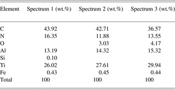
EDS elemental analysis of the a-CN/TiAlN double layer coating deposited on ASP30 steel after irradiation in vacuum atmosphere at the reduced laser intensity of I2 = 1.1 × 10¹³ W/cm2 was performed. The measuring locations are given in Figure 6. At this intensity, all elements recorded on a non-irradiated surface were detected at similar concentrations, Table 4.
Local EDS elemental analysis of the irradiated spot*.

* Measuring locations are given in Figure 6: 1 Laser pulse (spectra 1 and 2 – damage rim; spectrum 3 – damage center).
Generally, during laser-material interaction, the initial step of ablation comprises the absorption of laser radiation by free electrons in the conduction band (Bauerle, Reference Bauerle1996; Chichkov et al., Reference Chichkov, Momma, Nolte, Von Alvensleben and Tunnermann1996; Jeschke et al., Reference Jeschke, Garcia and Bennemann1999; Forster et al., Reference Forster, Egerhazi, Haselberger, Huber and Kautek2011). The energy is deposited in the region with thickness δ [skin depth (SD)] in which thermalization of the electron sub-system occurs. Due to electron thermal conduction and diffusion, energy transfers to the lattice and the heat is transported into the material. The energy transfer electron-lattice is terminated within several hundred femtoseconds. The so-called heat-affected zone is a maximum between SD and thermal diffusion depth (TDD) (Kononenko et al., Reference Kononenko, Garnov, Pimenov, Konov, Romano, Borsos and Weber2000). SD is defined as the reciprocal value of absorption coefficient (αeff) while TDD = (D × τl)1/2, where D and τ l represent the heat diffusivity and laser pulse duration, respectively. SD and TDD can be evaluated for our double layer a-CN/TiAlN coating. Using the value of 9 × 104 cm−1 (λ = 800 nm) for absorption coefficient of a-CN top layer (Forster et al., Reference Forster, Egerhazi, Haselberger, Huber and Kautek2011), the calculated SD is ~110 nm for single pulse regime. TDD is of the order of ~1 nm based on D = 0.2 cm2/s and fs pulse length. The D value used is for tetrahedral amorphous carbon (Forster et al., Reference Forster, Egerhazi, Haselberger, Huber and Kautek2011) since the diffusivity of amorphous carbon nitride (a-CN) is not known in literature. Larger SD than the TDD is expected due to the known fact that thermal effect in case of fs lasers is drastically reduced. Taking into account these calculations, it is possible to conclude that after 10 laser pulses the ablation depth should be ~1 µm, that is, the top layer of a-CN would be totally, and TiAlN layer partially removed. Results presented in Figure 3B2 confirm this assumption.
If the laser intensity in front of the material is high, as in our case, the plasma can be created at very high temperature. This plasma can sometimes cause the so-called shielding effect, since the plasma itself absorbs large part of the incoming laser radiation. This effect, however, is characteristic for laser pulses in nano- and pico-second time domain, while for fs pulses it is not present, or drastically reduced, since the pulse ends before the plasma can be formed. The pulse energy is therefore, deposited in the material without any substantial participation of laser–plasma interaction (Semerok et al., Reference Semerok, Salle, Wagner and Petite2002).
4. CONCLUSION
The study of interaction of fs laser with a-CN/TiAlN double layer coating on ASP30 steel substrate at moderate laser intensities is presented. Experiments were conducted at 1014 and 1013 W/cm2 intensity regimes with varying number of laser pulses. It was shown that these laser intensities at this specific coating combination can induce partial or total ablation of the coatings from the substrate. At the highest intensity (1014 W/cm2) coatings integrity was kept up to 10 accumulated laser pulses. In case of lower intensity (1013 W/cm2), a-CN layer is removed after several pulses, while the integrity of TiAlN is preserved up to about 50 pulses. Lower laser intensity produced periodic surface structures over the entire irradiated spot. LIPSS phenomenon can be of interest in micro-, nano-electronics, optics, etc. Laser pulse count of over 50 with the intensity 1014 W/cm2 created damages in the form of craters with depth up to 20 µm. Crater shapes are conical implying intensive processes taking place at the surface.
ACKNOWLEDGMENTS
The research was sponsored by: (i) The Ministry of Education, Science and Technology of the Republic Serbia through project “Effects of Laser Radiation on Novel Materials in Their Synthesis, Modification, and Analysis” (project No. 172019); (ii) COST-MP1208 action (‘Developing the Physics and the Scientific Community for Inertial Confinement Fusion at the Time of NIF ignition’); (iii) Ministry of Education, Youth and Sports of the Czech Republic (projects LD14089 and LG13029) and, (iv) Slovenian Research Agency (Research programme P2-0082-1). Authors would like to thank Dr P. Hribek and J. Hrebicek for their technical assistance in the course of experiment (especially assistance with femtosecond laser).