


1. Introduction
With advancements in robotics and automation, the capabilities to detect and maintain complex precision equipment have been significantly enhanced by a variety of specialized robots. These robots can effectively replace human beings in performing tasks that require narrow space operations [Reference Dong, Wang, Mohammad, Ba, Russo, Norton, Kell and Axinte1–Reference Ji, Song, Wang, Li and Song3]. Compared with conventional detection robots, hyper-redundant manipulators (HRMs) have better performances in diameter-to-length ratio, degrees of freedom (DOFs), and flexibility [Reference Walker, Choset and Chirikjian4]. They provide a more efficient and noninvasive solution for contactless operating tasks, e.g., assembling in space station [Reference Mu, Liu, Xu, Lou and Liang5], maintaining pipelines in nuclear power plants [Reference Buckingham and Graham6], and detecting in deep cavity of huge equipment [Reference Hwang and Kwon7, Reference Lauretti, Grasso, de Marchi, Grazioso and di Gironimo8].
Typical application scenario of HRM.

Since the first HRM was proposed by Robinson in 1999 [Reference Robinson and Davies9], various types of this robot have emerged in the past years. They can be roughly categorized in terms of their structures as a continuum type and the discrete one [Reference Kang, Guo, Chen, Branson and Dai10–Reference Kim, Kwon, Moon and Kim12]. Despite continuum HRM features an infinite number of DOFs in theory, it is obviously impossible to activate all DOFs in practice. In contrast, the discrete one has higher accuracy and load capacity due to several rigid links and corresponding active revolute joints, which is more suitable for contactless operating tasks [Reference Liu, Xu, Yang and Li13–Reference Cao, Zhang and Zhou15]. In our previous work, a cable-driven HRM with 16 independent DOFs was developed [Reference Ju, Zhang, Xu, Yuan, Miao, Zhou and Cao16]. As shown in Fig. 1, the HRM is designed to inspect the narrow inner chamber of an aircraft engine.
Redundant DOFs cause significant influence on HRMs’ dexterous control. Due to the strong nonlinearity and coupling constraints of HRMs, the motion planning and control of them pose significant challenges. Its core task is to find a collision-free trajectory under strictly environmental constraints. To solve it, various methods have been developed. In [Reference Luo, Li, Zhang, Tan and Liang17], Luo et al. propose a multiconstraint kinematic planning method based on variable redundancy kinematic model. They consider smoothness of joints and the mobility of base to obtain a collision-free path. Tian et al. [Reference Tian, Zhu, Meng, Wang and Liang18] design an improved artificial potential field method for path planning. In it, by restricting the movement of the manipulators to a virtual guiding pipeline, the environmental adaptability of them in confined environments are improved. In ref. [Reference Ji, Xie, Wang and Yang19], an ellipsoid-shape rapidly exploring random tree method is proposed to plan a trajectory in a tunnel-like route. Zhang et al. [Reference Zhang, Jin, Liu, Liu, Zhu and Zhao20] design an obstacle avoidance planning method based on the law of conservation of energy, which aims to ensure the smooth movement of the manipulator and avoid obstacles. Typically, expanded obstacles are commonly used to keep minimum safe distance in motion planning methods. However, in the process of expanding obstacles from their original size, there is a lack of established criteria for the expanded sizes. Each obstacle is uniformly expanded without distinction. Thus, these methods lack applicability in narrow deep cavities of aircraft engines.
In the domain of HRMs, various trajectory tracking control methods have been developed to make HRMs’ shape fit their path curve. Wei et al. [Reference Wei, Zheng and Gu21] present an autonomous motion planner with specialized rapidly exploring random tree for leader-following motion control of HRMs. In ref. [Reference Jiang, Yang and Shi22], a decoupling control strategy for HRMs is proposed. The movements between their body and links are decoupled to perform fast full-link trajectory tracking under complex disturbances. Gill et al. [Reference Gill, Kulic and Nielsen23] propose a frame curve-based method for path following control to determine the spline, which is currently closest to system outputs. Trajectory tracking-based motion planning methods have sufficient obstacle avoidance ability and high planning efficiency, which enhances the ability of HRMs to complete contactless operating tasks. Unfortunately, due to the discrete characteristic of HRM, it is not as flexible as the continuum robots. Thus, it is impossible to attain a perfect alignment with the path curve and only approximate trajectory tracking can be accomplished.
Despite the great progress of tracking-based motion planning methods, there is still a lack of consideration for potential collision areas during the tracking process. Besides, expanded obstacles may cause failed planning, especially in narrow environments. In this work, a local collision-free motion planning strategy based on dynamic safety envelope (DSE) is proposed. Its main contributions include:
-
The structural characteristics and local motion of HRMs are analyzed. The DSE is proposed for the first time to describe the boundary of the potential collision area arising from approximate path tracking.
-
In order to tackle the problem of excessive occupation of free space caused by expanded obstacles, the DSEs are applied to evaluate collision risks.
-
Based on the designed HRM and the proposed DSE, a local collision-free motion planning strategy is proposed to guarantee the safety and efficiency of planning in confined environments.
The remainder of this paper is organized as follows. Section 2 details the mechanism design and kinematics of our HRM. The DSEs are proposed and analyzed in Section 3. Section 4 presents the local collision-free motion planning strategy based on DSEs. The simulations and experiments are conducted in Section 5. Finally, a conclusion is drawn in Section 6.
2. Mechanism descriptions and modeling of HRM
2.1. Mechanism design
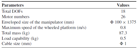
Our previous work has demonstrated the motion performance of a manipulator [Reference Ju, Zhang, Xu, Yuan, Miao, Zhou and Cao16]. In this work, our HRM is placed on a 2-DOFs wheeled platform to improve its wide-range mobility, as shown in Fig. 2. It is designed for delivering the robot tip to desired locations in aircraft engines by following the inner cavity. The main structure consists of a manipulator and a driving subsystem. The modular manipulator has 8 active universal joints with 16 rotational DOFs. It is driven by wire cables in order to provide accurate driving force and all driven cables are controlled by 24 driving modules. Each driving module is composed of a linear guide rail, slider, ball screw, coupling, DC motor, and motor driver. For faster installation and maintenance, the driving modules are arranged circularly. Its physical performances are listed in Table I.
Physical performance of HRM.
Mechanism design of the proposed mobile HRM.

2.2. Kinematics modeling
For motion planning of HRM in confined environments, it is crucial to obtain an accurate kinematics model. Based on the above mechanism design, the physical constraints are seriously considered. HRMs are usually modeled in the task, joint, and driving spaces. Respectively, their kinematics are further decomposed into two sub-kinematics as shown in Fig. 3.
2.2.1. Kinematics of the manipulator
During the motion planning process of HRM, the current posture of the end-effector is calculated according to the rotational joints. In this work, product-of-exponential (POE) method is applied to describe the geometrical relations of HRM and avoid singularity solutions [Reference Li, Wu, Lowe and Li24, Reference Yang, Kang, Branson, Chen and Dai25]. As shown in Fig. 3(a), a base coordinate system
 $B$
and an end coordinate system
 $E$
are established.
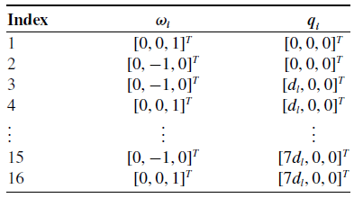
POE parameters of the proposed HRM are listed in Table II, where
 $\omega _{i}$
is the unit direction vector of each axis,
 $q_{i}$
represents the position of each joint. The motion of HRM can be described in the form of an exponential product as
 $e^{\hat{\xi } \theta }$
. Therefore, its posture of HRM can be expressed as
 \begin{equation} f_{1}=T_{B,E}(\theta _{1},\theta _{2},\theta _{3},\ldots,\theta _{16}) = e^{\hat{\xi }_{1} \theta _{1}} e^{\hat{\xi }_{2} \theta _{2}} e^{\hat{\xi }_{3} \theta _{3}} \ldots e^{\hat{\xi }_{16} \theta _{16}}T_{B,E}(0), \end{equation}
where
 $T_{B,E}$
represents the transformation matrix from
 $S$
to
 $B$
and
 $\theta _{1}, \theta _{2},\ldots,\theta _{16}$
are angles of rotational axes. The twist
 $\hat{\xi }_{i}=[\hat{\omega }_{i}, \nu _{i};\, 0, 0]$
, where
 $\hat{\omega }_{i}$
is the skew symmetric matrix of
 $\omega _{i}$
and
 $\nu _{i} = - \omega _{i} \times q_{i}$
. Besides,
 $T_{B,E}(0)$
is the initial posture of HRM. In this work, the initial joint angles corresponding to initial state of HRM are set as
 $\theta _{i} = 0^{\circ }$
.
POE parameters of HRM.
Kinematics of: (a) the manipulator; (b) the driven cables.

2.2.2. Kinematics of the driven cable
The main task in kinematics of the driven cable is to establish the mapping relationship between cable lengths and rotational joint angles. As shown in Fig. 3(b), a kinematic model is established to analyze the universal joint, and POE methods are applied to solve this problem.
 $M$
and
 $N$
are reference coordinate systems of two disks. The two rotational axes are intersect at the center of the universal joint.
 $h$
represents the vertical distance between the disk and center of the universal joint. Further, the POE parameters are described by
 $\omega _{M} = [0,\ 1,\ 0]^{T}$
,
 $\omega _{N} = [1,\ 0,\ 0]^{T}$
, and
 $q_{M} = q_{N} = [0,\ 0,\ h]^{T}$
. The initial posture of the joint is
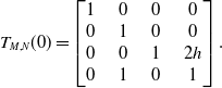 \begin{equation} T_{M,N}(0) = \begin{bmatrix} 1& \quad 0 & \quad 0& \quad 0 \\ 0 & \quad 1& \quad 0& \quad 0 \\ 0& \quad 0 & \quad 1& \quad 2h \\ 0 & \quad 1& \quad 0& \quad 1 \\ \end{bmatrix}. \end{equation}
Then, the transformation matrix from
 $M$
to
 $N$
is
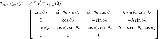 \begin{equation} \begin{aligned} T_{M,N}(\theta _{M},\theta _{N}) &= e^{\hat{\xi }_{1} \theta _{M}} e^{\hat{\xi }_{2} \theta _{N}}T_{M,N}(0) \\[3pt] & =\begin{bmatrix} \cos \theta _{M} & \quad \sin \theta _{M}\sin \theta _{N} & \quad \sin \theta _{M}\cos \theta _{N} & \quad h \sin \theta _{M}\cos \theta _{N} \\[4pt] 0 & \quad \cos \theta _{N} & \quad -\sin \theta _{N} & \quad -h\sin \theta _{N} \\[4pt] -\sin \theta _{M} & \quad \cos \theta _{M}\sin \theta _{N} & \quad \cos \theta _{M}\cos \theta _{N} & \quad h+h\cos \theta _{M}\cos \theta _{N}\\[4pt] 0 & \quad 0 & \quad 0 & \quad 1 \\ \end{bmatrix}. \end{aligned} \end{equation}
The cable length
 $L_{Ci}$
is the distance between the corresponding holes on disks, where
 $i$
is the index of each cable. The position of cables in
 $M$
is
 ${}^{M} C_{i}= \begin{bmatrix} \rho \cos \varphi, & \rho \sin \varphi, & 0, & 1 \\ \end{bmatrix}^{T},$
where
 $\rho$
is the distance from cable hole to the center of disk. After that, the kinematic of driven cables can be obtained as
 \begin{equation} \begin{aligned} L_{c}(\theta _{M},\theta _{N},\varphi ) &= \|T_{M,N}{}^{N}C_{\varphi }-{}^{M} C_{\varphi }\|\\ &=((\rho \cos \varphi (\!\cos \theta _{M}-1)+h\sin \theta _{M}\cos \theta _{N}+\rho \sin \varphi \sin \theta _{M}\sin \theta _{N})^{2}\\ &+(\rho \sin \varphi (\!\cos \theta _{N}-1)-h\sin \theta _{N})^{2}+(h(\!\cos \theta _{M}\cos \theta _{N}+1)-\rho \cos \varphi \sin \theta _{M}\\ &+\rho \sin \varphi \cos \theta _{M}\sin \theta _{N})^{2})^{\frac{1}{2}}. \end{aligned} \end{equation}
3. DSE-based collision detection method
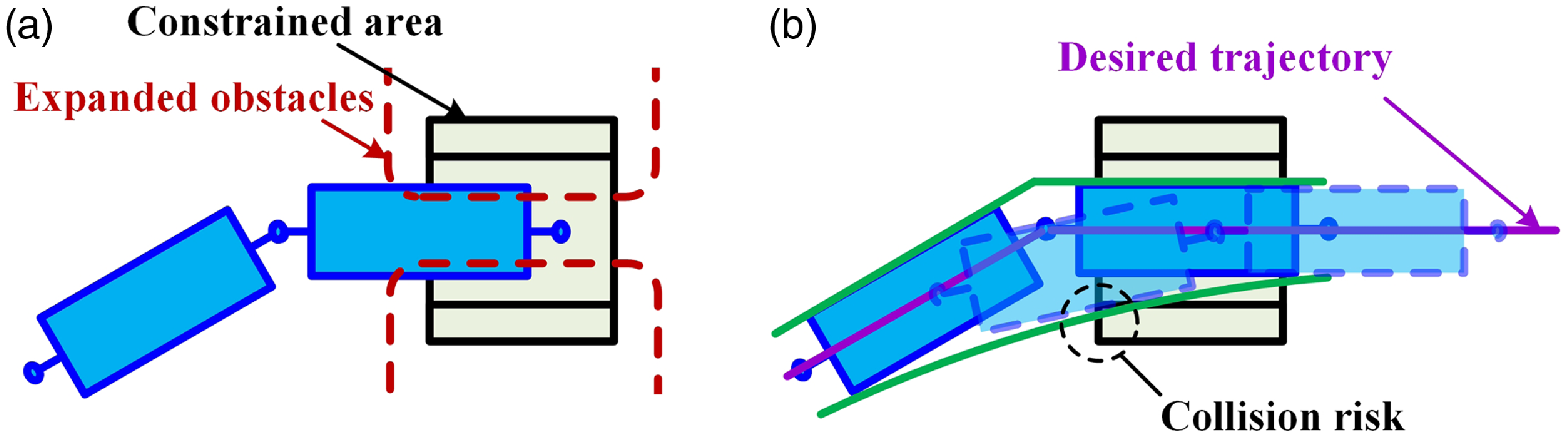
As shown in Fig. 4(a), free space for maneuvering will be occupied by using traditional expanding-based methods. Excessive-expanded obstacles result in the failure of the planning process. Besides, due to the HRM cannot completely track the trajectory, area swept by rigid links during the tracking process needs to be researched. As shown in Fig. 4(b), HRMs deviate from the ideal trajectory, and collision risks may occur. However, in the presence of obstacles, there lacks detailed analysis related to this swept area. Therefore, the collision detection method based on DSE is proposed.
Potential issues by using traditional methods during the trajectory tracking process: (a) excessive-expanded obstacles; (b) deviation from ideal trajectory.
3.1. Ladder problem
Ladder problem with: (a) L-shaped corner; (b) irregular corner.
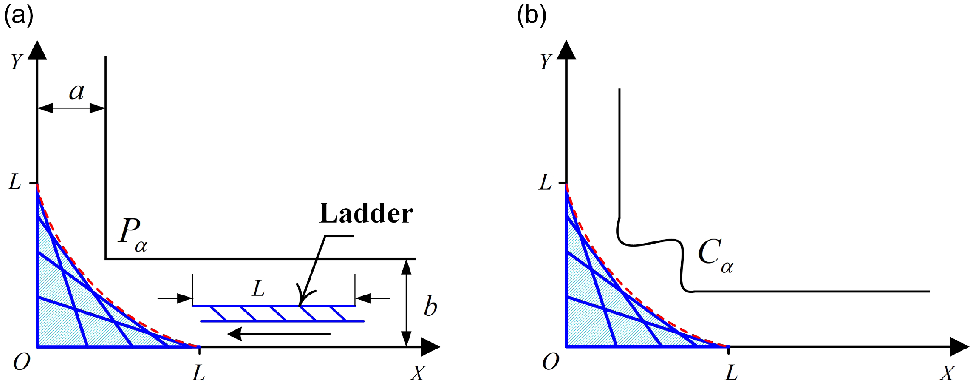
In order to provide a better understanding, the classical ladder problem is introduced first. As shown in Fig. 5(a), it can be described that how to operate a ladder to cross the L-shaped corner. In the idealized geometry, a line of constant length moves along the coordinate axes and forms a swept area. By definition, the envelope is a curve which is tangent at each of its points to the ladder. Interestingly, the envelope of this area is a part of a 4-cusped hypocycloid called astroid, with an equation in Cartesian coordinates:
 \begin{equation} x^{\frac{2}{3}}+y^{\frac{2}{3}}={L}^{\frac{2}{3}}, \end{equation}
where
 $L$
is the length of the ladder [Reference Dana-Picard26]. In order for the ladder to pass through the corner without collision, the corner point
 $P_{\alpha }(a,b)$
needs to be outside the envelope and satisfy
 $a^{\frac{2}{3}}+b^{\frac{2}{3}}\gt{L}^{\frac{2}{3}}$
.
Further discussion of the ladder problem is illustrated in Figure 5(b), where the L-shaped corner is replaced by an irregular corner. Accordingly, we assume that the irregular corner is formed by curve
 $C_{\alpha }$
, and
 $(x_{\alpha },y_{\alpha })$
is a point of
 $C_{\alpha }$
. To avoid collisions,
 $(x_{\alpha },y_{\alpha })$
needs to satisfy
 ${x_{\alpha }}^{\frac{2}{3}}+{y_{\alpha }}^{\frac{2}{3}}\gt{L}^{\frac{2}{3}}$
.
Similarly, collision risks occur where the trajectory is curved tightly during the tracking process of HRM. Inspired by the ladder problem, the potential collision area
 $C_{p}$
is defined as is the interior of the swept area. DSE is defined as the inner boundary curve of
 $C_{p}$
. The main properties of
 $C_{p}$
are
-
 $C_{p}$
usually occurs on the concave side of the trajectory.
-
When the curvature of trajectory tends to be infinitesimal, which means the trajectory tends to a straight line, the area of
$C_{p}$
tends to be infinitesimal.


3.2. Parameterization of DSE
An extended variation on the above ladder problem is shown in Fig. 6. When the tracking trajectory is no longer vertical, the other side of the ladder
 $P_{i+1}$
moves on any line passing through the origin of coordinates.
 $\alpha$
is the angle between the line and the horizontal axis.
To facilitate the calculation, the
 $X^{\prime}OY^{\prime}$
coordinate system is established with
 $\angle X^{\prime}OX= \frac{\alpha }{2}$
. In
 $XOY$
coordinate system, we assume that
 $P_{i}(u,0)$
,
 $P_{i+1}\left(v\cos{\alpha }, v\sin{\alpha }\right)$
, where
 $u\in [{-}1,0]$
and
 $v\in [0,1]$
. Then, in
 $X^{\prime}OY^{\prime}$
coordinate system, we have
 $P^{\prime}_{i}\left(u\cos{\frac{\alpha }{2}}, -u\sin{\frac{\alpha }{2}}\right)$
,
 $P^{\prime}_{i+1}\left(v\cos{\frac{\alpha }{2}}, v\sin{\frac{\alpha }{2}}\right)$
.
 $L_{d}$
is the length of
 $P^{\prime}_{i}P^{\prime}_{i+1}$
. In the derivation process, we assume that
 $L_{d}=1$
.
 $G(x^{\prime},y^{\prime},v)$
is defined as a family of lines with parameters
 $u$
and
 $v$
. According to
 $P^{\prime}_{i}P^{\prime}_{i+1}$
, it can be obtained:
 \begin{equation} G(x^{\prime},y^{\prime},v)= \dfrac{y^{\prime}+u\sin{\dfrac{\alpha }{2}}}{v\sin{\dfrac{\alpha }{2}}+u\sin{\dfrac{\alpha }{2}}}-\dfrac{x^{\prime}-u\cos{\dfrac{\alpha }{2}}}{v\cos{\dfrac{\alpha }{2}}-u\cos{\dfrac{\alpha }{2}}}. \end{equation}
By the cosine theorem in
 $\Delta P^{\prime}_{i}OP^{\prime}_{i+1}$
,
 $u$
and
 $v$
linked by the relation
 $(u+v)^{2}=1+4uv\cos ^{2}{\frac{\alpha }{2}}$
.
Illustration of geometric approach for DSE.

In general, the DSE can be obtained:
 \begin{equation} \begin{split} G(x^{\prime},y^{\prime},v)=0, \\[4pt] \frac{\partial G(x^{\prime},y^{\prime},v) }{ \partial v}=0. \end{split} \end{equation}
It represents that an envelope of the family
 $G(x^{\prime},y^{\prime},v)$
is a curve that is tangent to each member of the family at some point. By combining (6) and (7), the envelope in
 $X^{\prime}OY^{\prime}$
coordinate system is
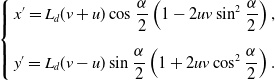 \begin{equation} \left \{ \begin{split} &x^{\prime} = L_{d}(v+u)\cos{\frac{\alpha }{2}} \left(1-2uv\sin ^{2}{\frac{\alpha }{2}}\right), \\[7pt] &y^{\prime} = L_{d}(v-u)\sin{\frac{\alpha }{2}} \left(1+2uv\cos ^{2}{\frac{\alpha }{2}}\right). \\ \end{split} \right . \end{equation}
Therefore, the corresponding envelope in
 $XOY$
coordinate system can be obtained in the form:
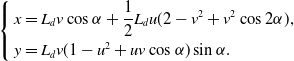 \begin{equation} \left \{ \begin{split} &x = L_{d}v\cos{\alpha } + \frac{1}{2} L_{d}u(2-v^{2}+v^{2}\cos{2\alpha }), \\ &y = L_{d}v(1-u^{2}+uv\cos{\alpha })\sin{\alpha }. \\ \end{split} \right . \end{equation}
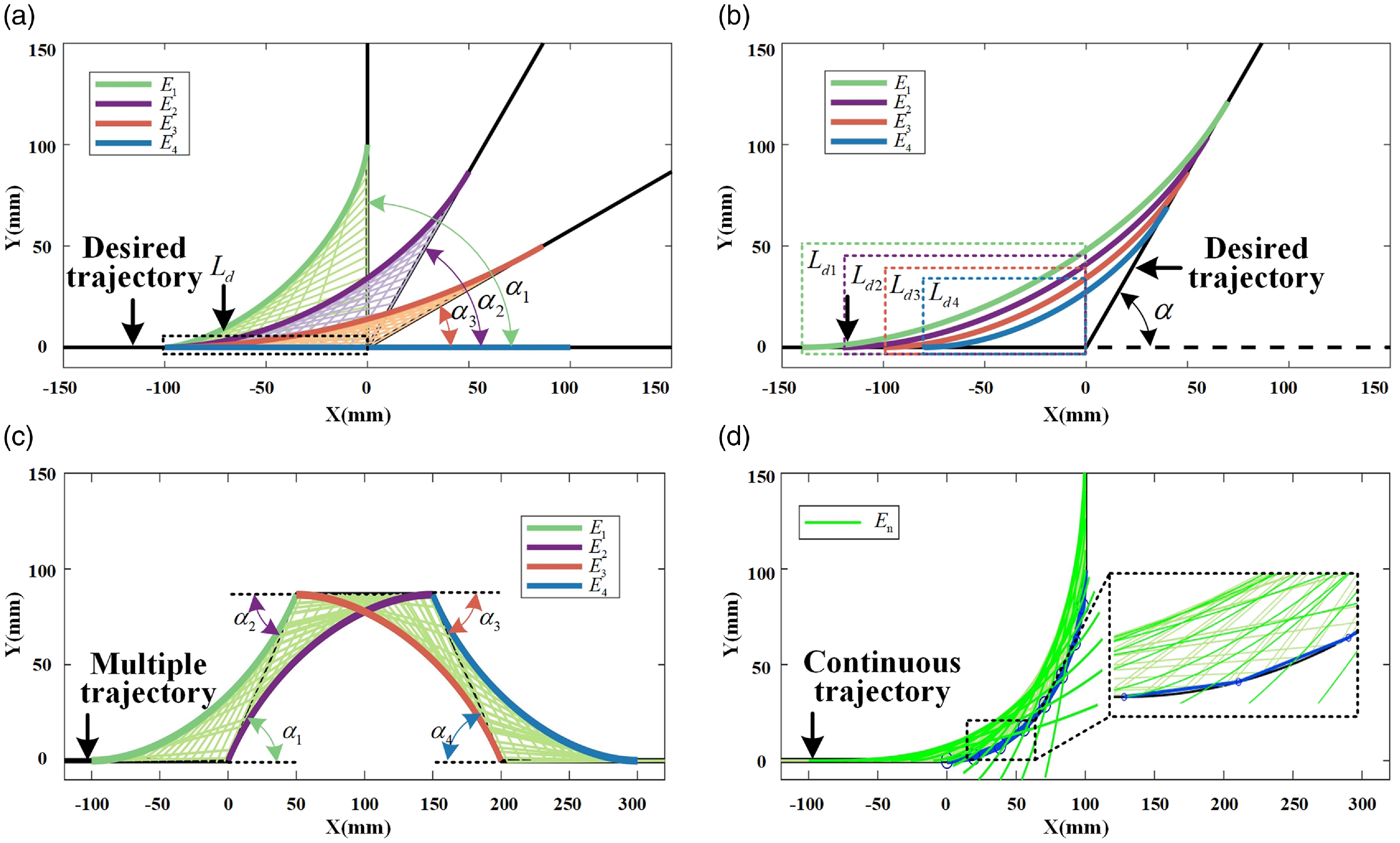
As shown in Fig. 7(a),
 $E_{1}$
-
 $E_{4}$
are envelope curves, and the potential collision area
 $C_{p}$
tends to be infinitesimal when
 $\alpha$
tend to be
 $0^{\circ }$
. It indicates that as deflection angle of the trajectory increases, the collision risk of HRM increases correspondingly. Figure 7(b) illustrates the positive correlations between
 $C_{p}$
and
 $L_{d}$
, which means the geometric parameters of the HRM are crucial in its ability to navigate through obstacles. Further, the potential collision area
 $C_{p}$
is formed by multiple envelope curves
 $E_{1}$
-
 $E_{4}$
in case of multisegment trajectories as shown in Fig. 7(c). Especially, if the trajectory is a continuous arc as shown in Fig. 7(d),
 $C_{p}$
can be formed by overlaying the envelopes of multiple discrete trajectories. By parameterizing the DSE, multisegment HRM can effectively avoid collision-risk areas.
Related properties of DSEs: (a) change
 $\alpha$
under constant
 $L_{d}$
; (b) change
 $L_{d}$
under constant
 $\alpha$
; (c) envelope curves of multisegment trajectories; (d) envelope curves of continuous trajectory.
3.3. DSEs considering the geometric dimensions of HRM
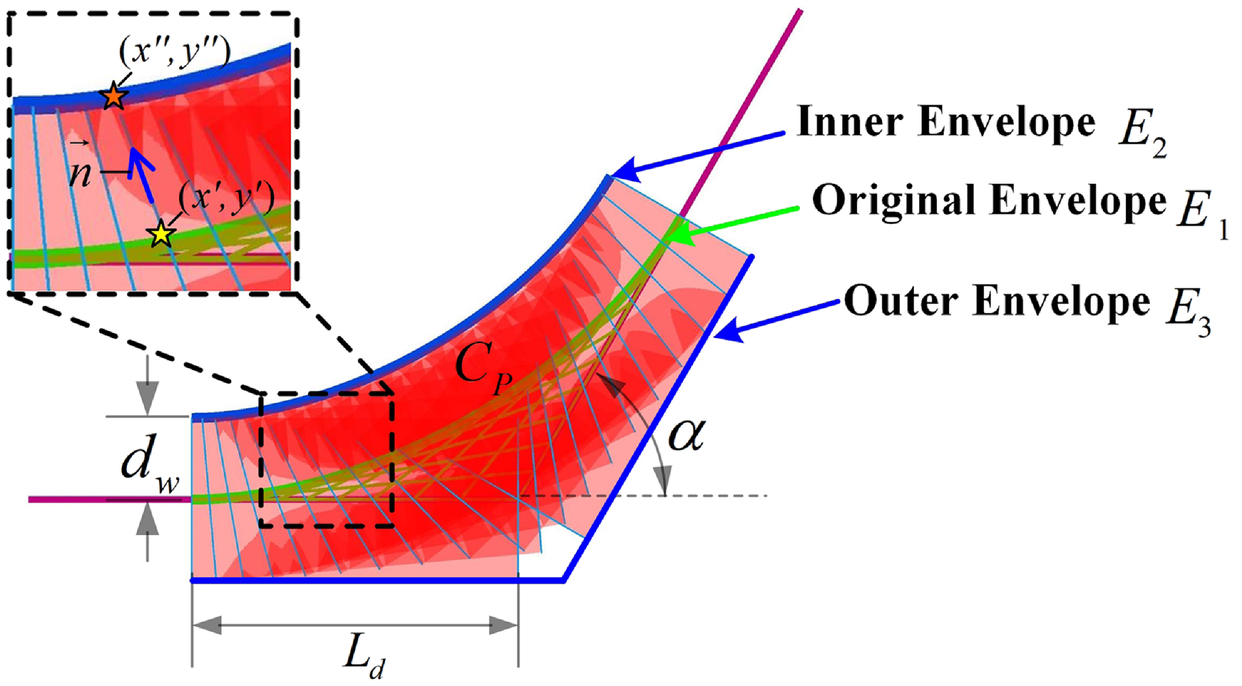
The authenticity of the scenario is enhanced by recognizing that the HRM actually has some positive width. As shown in Fig. 8, the centerline of HRM’s link is aligned with the tracking trajectory, which forms an original safety envelope
 $E_{1}$
. Similarly, an envelope
 $E_{2}$
occurs by the
 $H$
family, which consists of line segments separated from
 $G$
family by width
 $d_{w}$
. The parameterized representation of
 $E_{1}$
has been derived above, and the relationships between
 $E_{1}$
and
 $E_{2}$
are obtained in this part.
DSEs generated by actual cylindrical link.
In
 $X^{\prime}OY^{\prime}$
coordinate system, lines of
 $G$
family are described in (6), which can be rewrote as
 \begin{equation} G(x^{\prime},y^{\prime},v)=(u+v)\sin{\frac{\alpha }{2}}x^{\prime} + (u-v)\cos{\frac{\alpha }{2}}y^{\prime} -uv\sin{\frac{\alpha }{2}}, \end{equation}
where
 \begin{equation} \left((u+v)\sin{\frac{\alpha }{2}}\right)^2+\left((u-v)\cos{\frac{\alpha }{2}}\right)^2=1. \end{equation}
The normal unit vector of G is defined as
 \begin{equation} \overrightarrow{n}=\left((u+v)\sin{\frac{\alpha }{2}},(u-v)\cos{\frac{\alpha }{2}}\right). \end{equation}
To be convenient, the functions can be expressed as
 \begin{equation} \begin{split} & G(x^{\prime},y^{\prime},v)=\overrightarrow{n}\cdot (x^{\prime},y^{\prime}) - uv\sin{\alpha },\\ & H(x^{\prime},y^{\prime},v)=\overrightarrow{n}\cdot (x^{\prime},y^{\prime}) - uv\sin{\alpha } - d_{w}, \end{split} \end{equation}
Considering that
 $(x^{\prime},y^{\prime})$
is on the envelope of
 $G$
family,
 $(x^{\prime\prime},y^{\prime\prime})$
is the corresponding point that is
 $d_{w}$
units away in the normal direction. Thus, the
 $H$
family is
 \begin{equation} \begin{split} H(x^{\prime\prime},y^{\prime\prime},v)&= \overrightarrow{n}\cdot (x^{\prime\prime},y^{\prime\prime}) - uv\sin{\alpha } - d_{w} \\ &= \overrightarrow{n}\cdot [(x^{\prime},y^{\prime})+d_{w}\overrightarrow{n}] - uv\sin{\alpha } - d_{w} \\ &= G(x^{\prime},y^{\prime},v). \end{split} \end{equation}
Similarly, the partial derivative with respect to
 $v$
is computed as
 $\frac{\partial H(x^{\prime\prime},y^{\prime\prime},v) }{ \partial v}=\frac{\partial G(x^{\prime},y^{\prime},v) }{ \partial v}$
. The results show that if
 $H$
family consists of parallel lines in
 $G$
family separated by width
 $d_{w}$
, the envelope
 $E_{2}$
is the parallel of
 $E_{1}$
. In addition,
 $E_{3}$
is defined as the outer safety envelope. Obviously, it is parallel to the reference trajectory. Considering the geometric dimension, the ladder problem is transformed into couch problem. Indeed, as for the couch problem, the DSE and one of its parallel curves are applied to make it more in line with the actual situation of HRM.
 $C_{p}$
is defined as the potential collision area formed by the inner safety envelope
 $E_{2}$
and the outer safety envelope
 $E_{3}$
. In case of multiple obstacles
 $O_{n} = \bigcap \limits _{i=1}^{n} O_{i}$
, where
 $n$
is the number of obstacles, the collision avoidance conditions can be expressed as
 $\left \lbrace C_{p} \bigcap O_{n} = \emptyset \right \rbrace$
. In fact, evaluating potential collision areas rather than expanded obstacles gives more permissible space for motion planning.
4. Local collision-free motion planning strategy
Typically, deep cavities of an aircraft engine are more narrow and confined than normal environments, where more precise obstacle avoidance strategies are needed. Based on the designed HRM and the proposed DSE, a local collision-free motion planning strategy is proposed in detail. The motion planning of the HRM mainly includes two steps: a) configuration prediction, followed by b) configuration update. In the following, each module of the approach is described in detail.
4.1. Configuration prediction
To avoid failure planning results caused by over occupation of free space, the links’ collision volumes and potential collision area are not considered during the planning process. With the reference trajectory, the traditional tracking method is to fit its link to the desired curve. However, it is difficult to give the mathematical expression of continuous curve, which may cause more computation time. To fully utilize the potential of the DSE, a configuration switching-based planning strategy is first proposed by discretizing motion process. Different with the real-time link fitting method, our approach is to directly predict future configurations of the HRM.
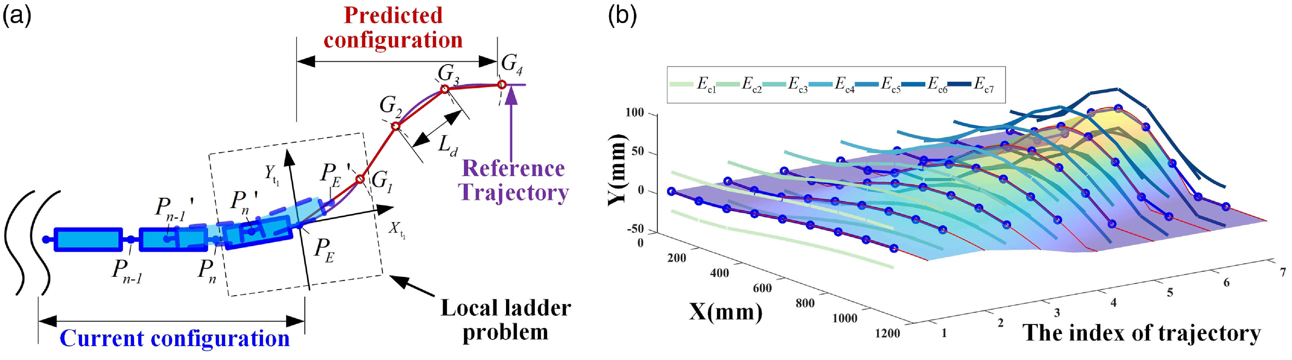
The configuration prediction method: (a) Illustration of the method; (b) prediction results of different reference trajectories.
The configuration update method of the HRM: (a) modeling of the internal environment of aircraft engine; (b) predicted configuration under the reference trajectory; (c) calculating DSEs and updating
 $G^{\prime}_{1}$
,
 $G^{\prime}_{2}$
; (d) updating
 $G^{\prime}_{3}$
,
 $G^{\prime}_{4}$
and predicting
 $G^{\prime}_{5}$
; (e) update result of collision-free configuration.

In order to provide the reader with a better understanding of the proposed method, a detailed illustration is given as shown in Fig. 9(a). The main idea of this method is tip-guided motion, which means that only the motion of the last two links is considered.
 $P_{n-1}P_{n}$
and
 $P_{n}P_{E}$
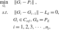
represent the current configuration of the last two links. To track the reference trajectory, the first step is to predict the next configuration of HRM. The statement of the problem is
 \begin{equation} \begin{split} \min _{G_{i}} \quad & \left \|G_{i}-P_{t}\right \|,\\ s.t. \quad & \left \|G_{i}-G_{i-1}\right \|-L_d=0, \\ & G_{i} \in \mathit{C}_{ref}, G_{0}=P_{E}\\ & i=1,2,3,\cdots,n_{j}, \end{split} \end{equation}
where
 $\mathit{C}_{ref}$
is the curve of the reference trajectory and
 $G_{i}$
is the point on
 $\mathit{C}_{ref}$
. Once the position of
 $P_{E}$
is determined, the next
 $n_{j}$
key nodes can be obtained. The distance between each two nodes is equal to the length of HRM’s link, which means that the future configuration can be predicted.
It’s worth noting that in the process of link
 $P_{n}P_{E}$
transfer to
 $P_{E}G_{1}$
, joint
 $P^{\prime}_{n}$
is on
 $P_{n}P_{E}$
and joint
 $P^{\prime}_{E}$
is on
 $P_{E}G_{1}$
. As mentioned in Section 3, it can be regarded as a local ladder problem with collision volume constraints. With the application of the DSE, the regions swept by the head links can be parameterized. Further, configuration prediction results are obtained from different reference trajectories as shown in Fig. 9(b).
 $E_{c1}$
,
 $E_{c2}, \ldots, E_{c7}$
are envelope curves of them.
4.2. Configuration update
After predicting the configuration, it is necessary to update the configuration according to the obstacle situation. As shown in Fig. 10(a), the main task for HRM is to keep the manipulator moving within intracavity without colliding with local obstacles. The whole DSE-based configuration update method for HRM is shown in Algorithm 1.
The DSE-based configuration update algorithm.

First, the desired configuration is predicted and
 $G_{0}, G_{1},\ldots, G_{4}$
are obtained via (15) as shown in Figure 10(b).
 $G_{0}$
coincides with point
 $P_{E}$
.
 $G_{1}, G_{2}, G_{3}, G_{4}$
are located on the reference trajectory
 $T_{r}$
and satisfy the distance constraints. Then, the envelope
 $E_{1,2}$
is calculated by considering
 $G_{0},G_{1},G_{2}$
as shown in Fig. 10(c). Obviously,
 $E_{1,2}$
is found in contact with the obstacle nearby. By fixing
 $G_{0}$
,
 $G_{1}$
is rotated by angle
 $\delta \theta$
in the direction away from the obstacle with
 $L_{d}$
as the radius of rotation where
 $\delta \theta$
represents the incremental angle for each iteration. Since our approach involves local updates,
 $G_{2}$
cannot deviate too far from the reference trajectory. After obtaining
 $G^{\prime}_{1}$
,
 $G^{\prime}_{2}$
is planned on
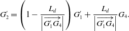
 $G^{\prime}_{1}G_{4}$
and calculated as
 \begin{equation} G^{\prime}_{2} = \left(1-\frac{L_{d}}{\left |\overrightarrow{G^{\prime}_{1}G_{4}} \right |}\right)G^{\prime}_{1}+\frac{L_{d}}{\left |\overrightarrow{G^{\prime}_{1}G_{4}} \right |}G_{4}. \end{equation}
The next step is to recalculate the envelope and assess collision risk according to
 $G_{0},G^{\prime}_{1},G^{\prime}_{2}$
. As shown in Fig. 10(d), the above steps are repeated until there exists no collision risks.
 $G^{\prime}_{3},G^{\prime}_{4}$
, and
 $G^{\prime}_{5}$
are predicted in the same way via (15). After a step-by-step optimization, a collision-free configuration within narrow aircraft engine can finally be obtained, as shown in Fig. 10(e). In the above example, the calculation of
 $G_{0},G_{1},G_{2}$
and the evaluation of collision are the key to our method.
 $G_{3}$
and
 $G_{4}$
are thoughtfully crafted to make the most of the reference trajectory
 $T_{r}$
, ensuring that all subsequent points are smoothly updated toward the ultimate goal.
It should be emphasized that the advantage of our strategy lies in the utilization of confined space. The geometric dimensions of HRM’s links and potential collision areas are considered in the envelope calculation process. On this base, the links are simplified into length-fixed segments, and obstacles are maintained in their original size.
5. Simulation and experimental validation
5.1. Simulations of HRM in narrow environments
In order to verify the proposed methods, simulations are implemented. This serves to illustrate the unique advantage of DSEs in motion planning. All of the numerical simulations are performed on a PC with an AMD Ryzen 7 3700X 8-Core Processor 3.60 GHz and 16-GB memory.
As shown in Fig. 11(a), the virtual model of an aircraft engine and a mobile HRM are established. The initial configuration of HRM is set to horizontal. The length of each rigid link
 $L_{d}$
is set to
 $128.5mm$
, the same size as the actual robot. The red arcs indicate the inner and outer boundary of the aircraft engine, and the distance between these boundaries is set to
 $500mm$
. The obstacles are tightly arranged within two boundaries and the radius of each obstacle is
 $60mm$
. In compact part, narrow gaps are set for HRM to pass through. The common method of expanded obstacles is shown in Fig. 11(b). To ensure the safety of planning, the link width
 $d_{w}$
and the potential collision areas are considered to calculate the expanded size of obstacles. In this work,
 $d_{w} = 25mm$
. According to (9) and (14), the maximum safety expanded size is set to
 $89.25mm$
where the path deflection angle
 $\alpha = 90^{\circ }$
. However, expanded areas excessively occupy narrow spaces, and there exists no free space for the HRM to obtain a proper trajectory.
Simulation of HRM in narrow environment by the proposed method.

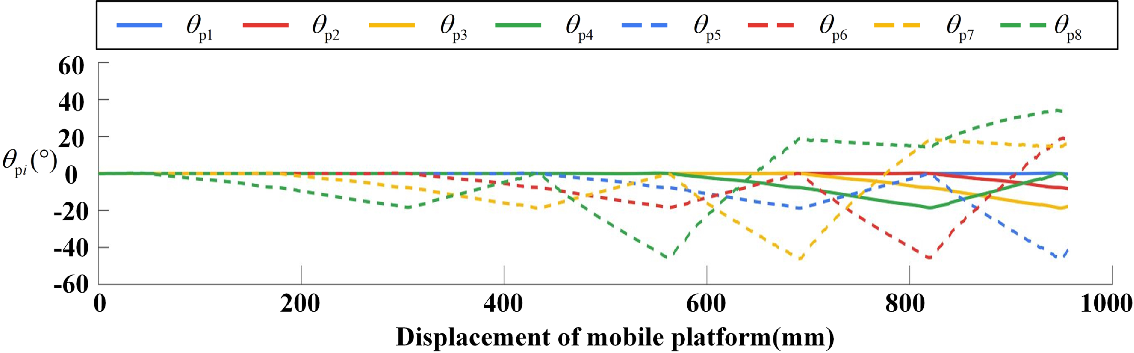
Pitch rotation joint angles of simulation.
Experiments of intracavity exploration by the proposed method.

The result of proposed method based on DSEs is shown in Fig. 11(c). The reference trajectory is obtained by the combination of an artificial bee colony algorithm and a particle swarm optimization algorithm [Reference Li, Wang, Yan and Li27]. The DSE is calculated, and the collision-free trajectory is obtained by our strategy. Figs. 11(d)-(f) show the trajectory tracking results during the movement of HRM.
As shown in Fig. 12, the pitch rotation joint angles
 $\theta _{p1},\theta _{p2},\ldots,\theta{p8}$
are solved.
 $\theta{p8}$
represents the end pitch rotation joint angle. Due to the tip-guided trajectory tracking method, the rest joints are followed sequentially by the end joint. The simulations indicate that the proposed strategy enable HRM to precisely avoid obstacles in confined aircraft engines.
5.2. Experiments of intracavity exploration
In this part, experimental validation is conducted on an actual HRM system to verify the adaptability of our strategy as shown in Fig. 13(a). In order to accomplish detection tasks in aircraft engine, an annular cavity is constructed first. The same virtual model is built in COPPELIASIM, as shown in the right part of Fig. 13(a). The HRM is supposed to cross a narrow space and reach the faulty electronic component to conduct detection tasks. In this experiment, the initial joint angles corresponding to initial state of HRM are set to
 $\theta _{i} = 0^{\circ }$
. Figs. 13(a)-(c) are current motion images of HRM move into obstacle array at t = 0s, 110s, and 200s, respectively. It is concluded that the proposed strategy makes HRM to avoid obstacles and reach the target point accurately.
6. Conclusion
Driven by the safety concern in contactless operating tasks, a local collision-free motion planning strategy is proposed for HRMs based on DSE. For the method, the tracking processes of HRMs are analyzed in detail, and the concept of DSE is first proposed to describe the boundary of the collision-free area. In order to guarantee the efficiency of motion planning in confined environments, trajectory of HRM’s end-effector is roughly planned without expanded obstacles. Further, the DSEs are applied to evaluate collision risk and optimize the trajectory in real time. Performances of our strategy are verified by simulations and experiments. Advantage of the DSE in the motion planning of HRMs is demonstrated.
Our strategy proposed in this work expands the potential of HRM in maintenance of narrow aircraft engines. Our future work includes dynamic modeling, energy optimization, and precise motion control of HRMs [Reference Aimedee, Gogu, Dai, Bouzgarrou and Bouton28–Reference Cao, Xiao and Zhou31]. The DSE can be extended to three-dimensional space. Furthermore, intelligent optimization and other advanced methods should be applied to improve the performance of HRMs [Reference Lin, Cao and Zhou32, Reference Li, Li, Wang, Guo, Wang, Zhang and Liu33].
Author contributions
Renjie Ju, Dong Zhang, Yan Gai, and Zhengcai Cao conceived and designed the study and wrote the article.
Financial support
This work was supported by the Beijing Natural Science Foundation (L223019, 3242011) and National Natural Science Foundation of China (52105005).
Competing interests
The authors declare no competing interests exist.
Ethical approval
The authors declare none.



