I. INTRODUCTION
It is well known that mechanical properties of metal products are significantly determined by the condition of the surface and its microstructure. Although an overall improvement in the base material can influence the properties remarkably, such changes, in most case, are not economic and sometimes even not accomplishable. On the other hand, the surface modification upon metal can be quite efficient in improving the fatigue, wear, and corrosion resistance of metal by changing the grain structure, hardness, and residual stresses.
Ultrasonic impact treatment (UIT), which was first invented in former Soviet Union in 1950s, Reference Krylov and Polischuk1,Reference Mukhanov and Golubev2 has attracted considerable attention over decades as a promising residual stress based post-weld surface treatment. This treatment involved a metallic striker or indenter oscillating at an ultrasonic frequency in an order of 18,000–27,000 Hz, and working piece will undergo treatment by direct contact with it. Enormous experimental studies have been reported to certificate the fascinating advantages of UIT, Reference Malaki and Ding3–Reference Vilhauer, Bennett, Matamoros and Rolfe9 including: (i) relaxation in stress concentration by smoothing geometrical profile, (ii) introduction of compressive residual stress, (iii) formation of a working hardening layer on surface, (iv) crystalline refinement to nanometer size, (v) reduction roughness as well as surface area, etc. Moreover, UIT devices are neither expensive nor complex and, in most case, portable. The treatment itself is convenient to carry out and environment friendly, which makes UIT a promising approach than traditional treatment.
However UIT is not a panacea inasmuch as it is a cold-work-based treatment which means the increase of working hardening also induce exacerbated ductility and plasticity. Surface damages caused by UIT have been indicated recently in literature. Reference Liu, Wang, Deng, Xia, Huo, Wang and Gong5 Yekta et al. Reference Yekta, Ghahremani and Walbridge6 applied UIT upon steel welded attachments at proper, under- and over-treatment. Even the over-treatment sample displays an improvement in fatigue life, the author eluded anxiousness for potential risky concern UIT in real application. Another problem was that strengthened layer introduced by UIT should not exceed a thickness of hundreds of microns, Reference Mordyuk, Prokopenko, Volosevich, Matokhnyuk, Byalonovich and Popova7,Reference Dekhtyar, Mordyuk, Savvakin, Bondarchuk, Moiseeva and Khripta8,Reference Abdullah, Malaki and Eskandari10 which means that the modification was confined within this scale and the properties varied in a large gradient along depth from the surface to the substrate.
Cold-working with subsequent traditional heat processing is a quite typical method to solve this problem. However the most common utilization of UIT is on wielded beams, more specifically, wielded toes, putting the whole wielded structure into furnace are not realistic. Heating the structure evenly might also cause grain coarsening, which deteriorate the mechanical properties and increase the cost of treatment shapely. Fortunately, electropulsing (EP) can be an alternative option as external energy input to replace the traditional heat treatment. The application of electropulsing is extensively studied and reported in many literature in recent years. The conclusions were quite exciting that EP could affect both plastic deformation, phase transformation, and recrystallization in some metals positively. Conrad and co-workers Reference Conrad11–Reference Conrad and Jung14 revealed that the introduction of a high energy current (density larger than 103A/cm2, depends on characteristics of metals) was able to trigger electro plasticity. As a result, it would contribute to reduce deformation resistance and increase strain rate in orders of magnitude. Jiang et al. Reference Jiang, Tang, Shek, Zhu and Xu15 applied EP on Mg–9Al–Zn alloy and found that EP accelerated dissolution of β phase in a short time due to reduction of nucleation thermodynamic barriers and enhancement of diffusion. Qin et al. Reference Rahnama and Qin16,Reference Samuel, Bhowmik and Qin17 investigated low carbon steel subjected to EP and found that EP is able to change the precipitation behavior of carbon atoms and affect the distribution of cementite. Ye et al. Reference Ye, Zion, Tang and Song18 applied EP to titanium alloy rolling process and endowed the final products with superior mechanical properties to cold-rolled ones. Wang et al. Reference Wang, Song and Tang19 performed a ultrasonic surface rolling (a similar treatment to UIT in present work) assisted with EP on 304 stainless steel and revealed that EP improved the surface hardness and wear resistance, and more martensite formed by strain-induced phase transformation. Therefore, EP is a potential high efficiency assisting treatment to ameliorate primary processing conditions and improve properties and performance of materials.
Present work focused on the D36 low carbon steel, which is an excellent material in the manufacture of ships, oil planes, and other ocean vessels or structures in which wielding is primary structural join method. Among these applications, the service condition could be corrosive and the load states be quite complex. Thus UIT has been adopted commonly upon wielding beam, which though to be vulnerability, in an aim to enhance the fatigue strength and corrosion resistance of overall structures. In this paper, D36 samples were subjected to both UIT and high energy EP simultaneously (EP-UIT). Some new phenomena have been revealed such as increment in hardness dramatically, phase morphology transition, and variation in chemical component. These discoveries might be supplement to the application of UIT.
II. EXPERIMENT
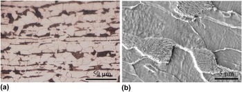
D36 steel studied in the current work was manufactured by Baoshan Iron & Steel. Co., Ltd, and the nominal composition of as-rolled material is 0.16C–0.22Si–1.54Mn–0.04Al–0.01Cr–0.002Nb (in weight%). The initial microstructure (as shown in Fig. 1) consisted of ferrite grains (light color) with an average size of 10 μm and pearlite colonies (dark color) with an average pearlite inter-lamellar spacing of 0.1 μm. Ferrite grains and pearlite colonies distributed in layers thus stratification structure paralleled to surface can be seen. The D36 steel was wire-cut into a cuboid-shaped sample and the dimension was 70.0 mm long, 12.5 mm wide and 14 mm thick.
Initial microstructure of the as-received sample: (a) OM and (b) SEM.

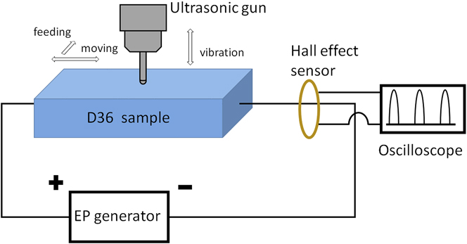
UIT equipment was provided by Huawin Electrical & Mechanical Technology Co., Ltd. (Jinan, China) with an energy output of 1 kW. Ultrasonic generator gave a vibration of 19.8 kHz. An alloy steel cylinder needle with semisphere tip (diameter 3.5 mm) was used as indenter. Static force between sample and indenter was provided by self-weight of ultrasonic gun, and indenter vibration peak to peak amplitude was 15 μm in this working parameter setting. In ordinary application, operators would manipulate UIT equipment manually which makes treatment could hardly be controlled precisely. Accordingly in present work ultrasonic gun has been installed on an altered milling machine and replaced the milling cutter. A pair of electrodes nipped both sides of sample longitudinally providing EP during UIT. The operation platform and join place between the steel frame fixing ultrasonic gun and the milling machine have be modified to be insulation in order that the current would totally go through the sample rather than leaking through the milling machine.
Electrical pulses were generated by a self-designed electropulsing generator. Electrical parameters were monitored by an oscilloscope. In this paper multiple current pulses with frequency 500 Hz and duration 95 μs were adopted. Peak current density and root-mean-square current density were 17.4 A/mm2 and 2.7 A/mm2 respectively. Temperature of the sample was measured by a K-type thermal couple during treatment concurrently. When the sample was subjected to EP, the temperature rising dramatically would be controlled around 380 °C by an air-blow cooling. Illustration of EP-UIT was shown in Fig. 2. Relative moving speed between the indenter and the sample was 3 mm/s, and the indenter gone through treated surface for 5 times, forth and back, in both UIT and EP-UIT.
Schematic configuration of EP-UIT.

After treatment the samples were wire-cut through treated zone to expose cross sections which were normal to the treated surface and parallel to the longitudinal direction of the sample. The cross section was ground on abrasive papers and polished with colloidal diamond paste according to standard metallographic process and etched in 3% nital solution. Hirox KH-7000 three-dimension optical microscope (OM; Hirox, Tokyo, Japan) and Hitachi S-4800 FEG scanning electron microscope (SEM; Hitachi Corp., Tokyo, Japan) operated in 50 keV were used to catch microstructural images of the treated surface or cross section. Element components in a micro region were examined by energy dispersive x-ray microanalysis system (EDX) equipped in SEM. X-ray diffraction (XRD) measurement was performed in Bragg geometry with Cu Kα radiation. A Rigaku micro-diffraction goniometer (Rigaku Corp., Tokyo, Japan) running at 40 kV/200 mA was used to scan a 2θ from 10 to 90° to characterize the phase composition of treated surface. Micro-hardness of the cross section and treated surface were measure by a micro-hardness tester. A diamond indenter was operated with static load of 50 gf and duration of 15 s. Measurement has been repeated for 5 times in each depth to get an average value. The depth of measurement on the cross section was not shallower than 40 μm from treated surface since the indenture has a dimension around 30 μm.
III. RESULT
A. Microstructure
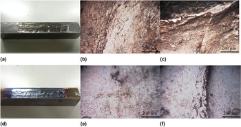
The surface of samples treated by UIT and EP-UIT were shown in Figs. 3(a) and 3(d) respectively. The indenter left grooves with depth around 0.3 mm on treated surface of both UIT and EP-UIT. When operation platform moved, the ultrasonic gun was subjected to a friction torque due to insufficient lubrication. Consequently, the uneven deformation caused by discontinuous movement of indenter leads to arc-shaped ridges. Figures 3(b) and 3(c) present the OM images of flat region and a ridge on UIT treated surface which reveals tiny pores and cracks, as well as wide and complex shaped ridge. These macro defects could be fatal in its service, as they might become the source of stress concentration and crack initiation. The surface subjected to EP-UIT possessed a violet tinge with metallic luster caused by oxidation [Fig. 3(d)]. The microstructure indicated that EP-UIT surface [Figs. 3(e) and 3(f)] was much smoother than UIT surface. This is presumably attributed to less crack and narrower area of ridge. It might be caused by two reasons: firstly, the deformation brought about by EP-UIT is usually more homogeneous despite discontinuous movement; secondly, the surface oxidation results in a volume expansion, and the macro defects could be abated or covered. More details concerning the oxide layer will be discussed in subsequent chapters.
Surface quality: (a) UIT, (d) EP-UIT; OM image of treated surface: (b and c) UIT, (e and f) EP-UIT.

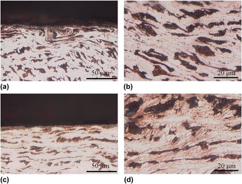
Cross section of UIT sample was shown in Figs. 4(a) and 4(b). It is clear that the superficial layer (30 μm from surface) undergoes severe plastic deformation. The pearlite colonies have been greatly twisted and elongated to narrow stream shape, and they sometimes overlapped with each other. Though pronounced variation in morphology, most “pearlite streams” maintained continuous and unbroken with clear boundaries against ferrite grains. Some area has been rotated to form whirlpool-shaped structure that revealed heterogeneous and complex deformation. Beneath the superficial layer, strain decreased with depth increment, thus pearlite colonies deformed and kept integral bulk shape. Ferrite boundaries were elongated and ferrite grains became irregular nonequal-axial grains as shown in Fig. 4(b). They were adherent to regular pattern of cold-work based deformation.
OM images of cross section: (a and b) UIT; (c and d) EP-UIT.

The microstructure of EP-UIT specimen was considerably distinguishing from UIT, as displayed in Figs. 4(c) and 4(d). An oxide layer (3–5 μm in thickness) covered the treated surface evenly. In some region, oxide layer was discontinuous and the interior metal is exposed, which might be accordant to the tiny spots in Fig. 3(e). As long as both UIT and EP-UIT were executed in the same ultrasonic power output and treatment intensity, superficial layer should also be severe plastic deformed structure. However, stream-shaped pearlite has been replaced by island-shaped pearlite in EP-UIT. More boundaries and pervasive structure which might be induced by the redistribution of cementite [as shown in Fig. 4(d)] have developed within ferrite matrix during EP-UIT. It is noticeable that so abound in quantities were boundaries that it almost occupied light area of ferrite compared with UIT microstructure in which less boundaries could be found. These boundaries might consist of initial boundaries and newly formed ones which emerged with development of dislocation network. It is reasonable to assume that the ferrite grains have been refined and this refinement was different from that of UIT. Further work should be performed to provide more evidence.
Figure 5 presented typical SEM micrograph of UIT and EP-UIT samples. Severe plastic deformation layer under UIT was indicated in Fig. 5(a). Pearlite colonies have been squeezed into streams in accordance with the OM image in Fig. 4. However cracks can be found on the very superficial region and it could propagate along the pearlite streams to dissociate nearby structure as shown in Fig. 5(b). These cracks were detrimental in service, as the surface layer could be stripped from substrate. Furthermore, macro crack might initiate and propagate on the basis of these micro cracks. Integral stream-shaped pearlite was presented in Fig. 5(c) (about 50 μm from the surface). Pearlite lamellas have been squeezed to reduce the interlamellar spacing to the extent that cementite almost directly contacted with neighbor layers.
SEM of the cross section of superficial layer: (a) UIT general view, (b) crack along cementite streams, (c) deformed pearlite colony, (d) EP-UIT general view, (e) superficial layer and oxide, (f) transition region of spheroidized cementite.

As shown in Fig. 5(d), EP-UIT introduced an oxide layer. Since most metal oxidation proceed in a manner that oxide grows into the metal substrate, the boundary between oxide layer and the matrix is not quite flat. In contrast to UIT microstructure lamellar pearlite is hardly found beneath the oxide layer as well as the cracks along it, and spheroidized cementite particles [as shown in Fig. 5(e)] with average diameter around 200 nm scattered within the ferrite matrix in replacement. This difference in morphology signified that cementite redistribution occurred in this region during EP-UIT. Spherical cementite particles is gradually replaced by the original lamellar pearlite colony with the increase of depth. Therefore, there was a transition region in a depth around 20–50 μm presented in Fig. 5(f). It is noticed some colonies that shattered and under gone spheroidization coexisted with integral lamellar colonies.
B. Microhardness
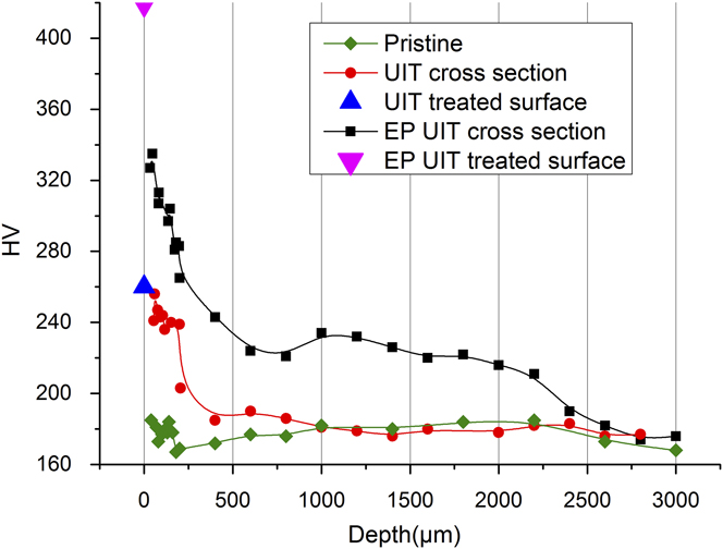
Figure 6 indicated variation of Vickers micro hardness measured on cross section as a function of depth from the treated surface to the interior substrate, as well as the average micro hardness of treated surface denoted by triangle icons. Pristine structure has an average micro hardness of 175 HV. After UIT, the micro hardness of superficial layer increased to more than 240 HV. This could be attributed to the working hardening introduced by the large strain on the surface. The micro hardness measured from treated surface (blue triangle) was around 260 HV, which was close to the value obtained from cross section. Thus one can say micro hardness in superficial layer of UIT sample was continuous, since the microstructure, morphology, and chemical component were all continuous. Then the strain declined swiftly with the depth increment into interior metal as well as hardness which returned to the pristine value in a depth of 300 μm approximately. A hardness reduction of about 80 HV occurred within such a narrow region demonstrated that there was a large (absolute value) gradient of hardness versus depth. A number of literature Reference Malaki and Ding3,Reference Mordyuk, Prokopenko, Volosevich, Matokhnyuk, Byalonovich and Popova7,Reference Dekhtyar, Mordyuk, Savvakin, Bondarchuk, Moiseeva and Khripta8,Reference Abdullah, Malaki and Eskandari10 have reported the general dependence between hardness and depth by UIT, then it is declared in their work that the metal on superficial layer was able to gain a maximum hardness enhancement by 40–100%, depending on the chemical composition, ultrasonic equipment, process parameters, etc. However, it is noticeable that the strengthened layer is confined within 400 μm (generally it should be 200 μm) when the surface is subjected to a common and practical treatment intensity. Obviously the present UIT result was in accordance with literature reports.
Micro hardness in dependence of depth.
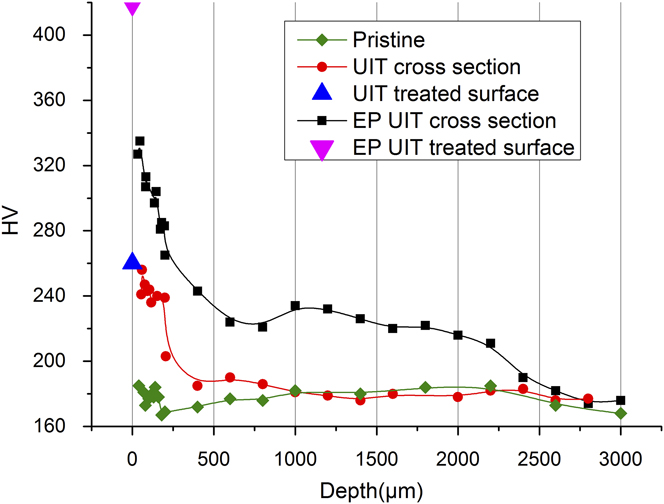
However, EP-UIT seems to surmount this limitation, as depicted by the black curve. Two sections of region could be discerned in terms of different gradient of hardness distribution. The first section was superficial layer whose thickness was about half millimeter with similar hardness gradient of UIT superficial layer. Nevertheless, the increment in hardness was almost twice the value of UIT. Specifically, the micro hardness measured from treated surface (denoted by the purple triangle), which was actually the hardness of oxide layer, exceeded 400 HV. As a result, there was a gap in hardness between the treated surface and the cross section, because of the discontinuity in structure and chemical components. The second region beneath half millimeter particularly extended to a depth of more than 2 mm with its hardness between 240 and 200 HV varying in a relative small gradient. Even though both OM and SEM exhibited a coarse grain structure whose dimension and morphology were the same as pristine sample, a hardness increment of about 25% definitely has been introduced into this region. Subsequent validation test also confirm the results presented here.
C. Surface chemical composition
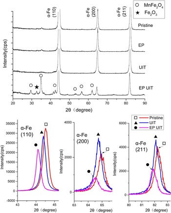
The XRD patents of pristine specimen, EP solely, UIT solely, and EP-UIT samples were presented in Fig. 7. There was no difference in characteristic diffraction patent that correspond to α-Fe (110), (200), (211) between pristine sample and EP, even though sample treated by EP was covered by purple tinge for surface oxidation induced by exposure to air in high temperature during EP. However, no diffraction peak of oxide was found, demonstrating that the oxide was insufficient in amount to provoke detectable characteristic diffraction. Then XRD of UIT sample showed similar patent with the pristine sample except for a peak deviation toward low diffraction angles. This could be explained by the compressive residual stress introduced by UIT. Another explanation may be the increment in lattice parameters caused by the interstitial solid-solution atoms.
XRD patent of the treated surface experienced EP, UIT, EP-UIT, as well as pristine sample.

Beside original α-Fe, characteristic diffraction peak of oxide can be seen in EP-UIT. These new phases have been identified as two types of compounds. The first one was MnFe2O4 as well as its allotropic substance with different stoichiometrical number such as Fe3Mn3O8 or FeMn2O4 etc. who shared the same characteristic diffraction patent. Another one was hematite despite its diffraction intensity was much weaker than MnFe2O4 thus it can be concluded that hematite did exist in the oxide layer but by a very small fraction. In analogy to UIT, the peaks of α-Fe also shifted toward low diffraction angle, but by a deviation larger than UIT. Taking the new compounds and elements engaged by EP-UIT into consideration, it is rational to postulate that both compressive residual stress and solid-solution induced increment in lattice parameter lead to diffraction peak displacement, but the latter probably would make more contribution.
Moreover, UIT introduced a redistribution of intensity of peaks, which might be attributed to reorientation of grains induced by plastic deformation. It can be found that the intensity of reflection (110) dropped as well as (200) (211) elevated after UIT. However there were several new compounds emerged in EP-UIT, which occupied a fraction of the global diffraction intensity, so the α-Fe reflection dropped dramatically and the comparison with pristine intensity lost its meaning.
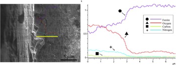
An EDX line scanning on cross section was performed vertical to the treated surface to reveal the chemical composition and the distribution of superficial layer, as shown in Fig. 8. A high oxygen concentration was traced on the superficial layer as decreasing sharply in a depth of 3 μm which was the interface between the oxide layer and the matrix. Thus the distribution of oxygen was in accordance with SEM images. The iron kept its concentration uniform without perceivable variation. According to XRD analysis, the oxide layer was identified as MnFe2O4 and hematite. However, the overall manganese content in the bulk was only 1.54% in mass fraction, and the MnFe2O4 contained very limited amount of oxygen atoms, even if all the manganese was consumed by the formation of MnFe2O4. In addition, the hematite intensity was very weak signifying a destitute amount. Superfluous oxygen atoms can only react with ferrite to form amorphous oxide so that there was no characteristic diffraction peak. Identical phenomenon has been captured by M.A. Vasylyev and coworkers Reference Vasylyev, Chenakin and Yatsenko20 in their experiment investigating the UIT induced oxidation of Ti6Al4V. A small amount of nitrogen atoms was also detected without any nitride being identified by XRD, which might lead to a postulation that nitrogen atoms diffused into the layer to form solid solution, or, as analyzed in Ref. Reference Vasylyev, Chenakin and Yatsenko20, complex amorphous nitride or oxynitride. Nevertheless, nitrogen atoms contributed to the high hardness in superficial layer.
EDX analyze upon oxide lay from cross section.

IV. DISCUSSION
The present work, EP and UIT, involved two different treatments. UIT was in essence a mechanical treatment based on stress and strain, given that material was subjected to impaction load in ultrasonic frequency. On the other hand, EP referred to two kinds of influences upon material based on different physical mechanism: electro plasticity stimulated by drifting electrons as athermal effect, and Joule heat brought about by current heating as thermal effect. Thus the following discussion concentrates on the influences and interaction of the three factors on tested material.
A. The effect of UIT
The effect of ultrasonic energy on the deformation behavior of metal and alloys, acknowledged as acoustic softening, has been investigated for decades. Reference Siddiq and El Sayed21–Reference Siddiq and El Sayed24 It was found that during plastic deformation, ultrasonic energy reduced the yield stress of specimen in analogy to thermal softening. Ultrasonic energy only concentrated in specific regions, such as vacancy, dislocation, grain boundary, etc. which were dominant in plastic deformation. However, thermal energy was absorbed uniformly among material. Thus it costs much less ultrasonic energy than thermal energy by several orders of magnitude to procure a similar softening. It was also found the reduction of yield stress was proportional to the intensity of ultrasonic energy. Obviously, UIT draws benefit from acoustic softening to facilitate the deformation as well as other ultrasonic processes. Therefore, severe plastic deformation (SPD) could be achieved within a small region by fairly small power output.
Dislocation behavior and its evolution were crucial in the comprehension of the effect of UIT. Specimen subjected to UIT experienced a deformation induced grain refinement, and this phenomenon has been studied by N.R. Tao and co-workers, Reference Tao, Wang, Tong, Sui, Lu and Lu25,Reference Roland, Retraint, Lu and Lu26 concerning surface mechanical attrition treatment (SMAT) as a similar surface mechanical modification process as UIT. The authors proposed that the grain refinement process consisted of several steps: development of dislocation walls and tangles in original grains; transformation of dislocation walls and tangles into subboundaries separating the grains; evolution of subboundaries into high angle misoriented boundaries. Finally there was an equilibrium between the multiplication and annihilation of dislocations, indicating a limitation of grain refinement. In UIT, more specifically, work hardening was induced by the high density of dislocations in the superficial layer. Then stress decreased as depth increased, so that less strain as well as work hardening could be introduced in deeper layer. That also explained different morphologies along the depth and the variation in micro hardness. Then the pearlite colonies consisting of cementite and ferrite lamellas were more complex in deformation as long as cementite was much harder than ferrite. It can be inferred that pearlite colonies might rotate to a preferential orientation to satisfy a further deformation. As shown in Fig. 5(c), the interlamellar spacing of pearlite was reduced dramatically. Thus it is reasonable to postulate that the ferrite lamellas in the pearlite as well as the ferrite close to cementite/ferrite boundaries might accommodate a large strain. Accordingly these areas in superficial layer could be a vulnerability due to the existence of a high density of dislocations and other defects. Compressive residual stress, Reference Malaki and Ding3,Reference Liu, Wang, Deng, Xia, Huo, Wang and Gong5,Reference Mordyuk and Prokopenko27–Reference Liao, Chen and Bellinger29 whose value was close to the yield stress, has been exerted upon specimen because of deformation induced lattice distortion. In addition to the enhancement of hardness, shallow initial defects were affected by the deformation so that crack nucleus and development would be retarded according to A.I. Dekhtyar's investigation. Reference Dekhtyar, Mordyuk, Savvakin, Bondarchuk, Moiseeva and Khripta8 All these factors provided advantages in prolonging fatigue life which have been acknowledged prevalently, however deteriorated ductility caused by high density dislocations might become unsafe and insecure factors to mechanical property. An over treatment developed a tendency to create cracks as shown in Fig. 5(b) which might also store potential risk in the application.
B. The effect of EP in UIT
1. Electro plasticity
When electropulsing has been exerted upon deforming metal, deformation would be affected for interaction between drifting electrons and dislocations. Additional force has been applied on dislocations by drifting electrons which was described by the following formula derived in consideration of quantum mechanism Reference Conrad, Sprecher and Nabarro12 :
 $${F_{{\rm{ew}}}} = a{\bi{b}}{{\bi{p}}_{\rm{F}}}\left( {{\bi{j}} \cdot {e^{ - 1}} - {n_{\rm{e}}}{\bi{v}}} \right)\quad ,$$
where α = 0.25–1.0, b the Burgers vector, p F the Fermi momentum, j current density, e the electron charge, n e electron concentration, and v the dislocation velocity. It is worthy to note that F ew increases with j linearly. As long as mechanical force applied on metal specimen was not so strong that dislocations mobilized in a relatively small velocity (more specifically several orders of magnitude slower than sound speed in the same elastic medium) and spend most of the time in overcoming the obstacles, F ew is a positive value that granted dislocations additional promotion force to surmount obstacles which were elastic interaction with structural barriers such as Peierls stress and defects. Reference Conrad, Sprecher and Nabarro12 With assistance of F ew, new dislocation sources and slip system might be subjected to sufficient stress and be activated inducing further deformation. In terms of experimental measurement, a drop in flow stress or softening would be detected.
In the present work, specimen temperature rose to around 380 °C induced by Joule heat. Thermal effect of softening could not be ignored as long as dislocations is able to overcome the energy barriers easily with thermal fluctuation. This process is well acknowledged in terms of transition state theory in which temperature occupied the exponential term and behavior of dislocation is sensitive in dependent of temperature especially in high temperature. It is quite interesting to found that three softening effects based on different physical mechanism have been involved in EP-UIT. Acoustic softening and electro plasticity seemed to concentrate the energy (mechanical and electrical) on defects, however thermal softening was uniform. Unfortunately it is indiscreet to sum the three softening effects up algebraically because an absolute and intrinsic comprehension of acoustic softening and electro plasticity were still unavailable let along a sophisticated theory or model to combine the three. A conservative or definitive statement should be that all of the three effects gave contributions and a considerable total softening could be achieved. As a result plastic deformation layer extended to a depth that cannot be affected by UIT solely. However the mechanical stress was so weak in this region that only the dislocations or sources who possessed advantages in orientation could be activated. Thus an increment in hardness could be found, mainly resulted from the increment in dislocation density rather than changes in profile and morphology.
Besides the drop in flow stress, the evolution of dislocations might be quite different from that of UIT solely. Mobilization of dislocations have been facilitated owning to athermal and thermal effect of EP, accordingly enhancement in dislocation velocity as well as strain rate were expected given that the strain rate is a function of dislocation velocity. Reference Sprecher, Mannan and Conrad30 As discussed in UIT, there were two contradictory and competing processes in deformation induced refinement: dislocation multiplication to satisfy plastic deformation and annihilation into dislocation walls and tangles as well as subsequent subboundaries and boundaries. Both processes would be accelerated by the effect of EP. With the assistance of thermal activation, deformed structure has the tendency to release stored energy by rearrangement or annihilation of dislocation that resulted in a development of substructure. As a result, it is reasonable to postulate that a fully developed deformation induced grain refinement structure with high hardness would be accomplished. More investigations will be performed to extract evidences of the postulation.
2. Morphology of pearlite
As shown in Fig. 5(c), pearlite interlamellar spacing has been reduced dramatically during deformation, thus the thermal dynamic equilibrium between the free energy of phase transformation and the interfacial energy is broken. Pearlite transformation could be deemed as γ → α + Fe3C. For an equilibrium phase transformation, the reduction of Gibbs-free energy is balanced by the increment in interfacial energy between ferrite and cementite, which can be depicted as follows Reference Rahnama and Qin16 :
 $$\Delta H\cdot S\cdot\rho \left( {{T_{\rm{E}}} - T} \right)/{T_{\rm{E}}} = 2\sigma\quad ,$$
where ΔH is latent heat of transformation, T E is eutectoid temperature, T is transformation temperature, S is interlamellar space, ρ is mole per unit volume, and σ is interfacial energy per unit area. If interlamellar spacing was narrowed, there will be a tendency to reduce interfacial energy by contraction of interface between ferrite and cementite. Furthermore, EP created additional change in the free energy of structure, denoted by ΔG EP, which originated from the redistribution of current, as induced by the difference in resistance between phases. Then Eq. (2) became Reference Rahnama and Qin16 :
 $$\Delta H\cdot S\cdot\rho \left( {{T_{\rm{E}}} - T} \right)/{T_{\rm{E}}} = 2\sigma + \Delta {G_{{\rm{EP}}}}\quad .$$
In case of pearlite, the resistance of cementite is much larger than ferrite, ΔG EP > 0. As a result, the structure subjected to EP-UIT would deviate further away from thermal dynamic equilibrium state than UIT, which means both deformation and EP gave contribution to a driving force of cementite redistribution to satisfy the thermodynamic equilibrium. Rather than increasing interlamellar spacing, the spheroidization of cementite seems to be more efficient in reducing the free energy. Not only could interfacial area be decreased by spheroidization of cementite, but also the total resistance of structure as well as ΔG EP, according to Qin's work, Reference Rahnama and Qin16 would be reduced prominently. The explanation is that EP is able to configure conductive phase to a state of minimum resistance, in which cementite became spherical particles rather than lamella.
Apart from thermodynamic driving force, kinetic requirement has to be satisfied in the redistribution of cementite. Diffusion of carbon atoms became available only when thermal activation is engaged. Thus there would be no diffusion-dominated cementite redistribution in UIT solely. The flux of carbon atoms can be determined as follows Reference Conrad13 :
 $$\emptyset = \left( {kT{{\partial \ln N} \over {\partial x}} - \Omega {{\partial \sigma } \over {\partial x}} + {Z^*}e\rho {\bi{j}}} \right)\cdot ND/kT\quad .$$
Outside the brackets N is atomic density, D is diffusion coefficient which can be depicted by transition state theory and became perceivable in relatively high temperature, k, T their common meaning. Inside brackets, however, were different forces acting on particular atoms. The first term, where
x
is distance along diffusion direction, is concentration gradient. So that it is actually Fick's law. The second term, where Ω is atomic volume, σ the stress, is function of stress gradient. It indicated that compressive stress gradient will retard the flux while tensile stress will promote it. In present work's case, it might provide a force to drive the carbon atoms drifting from the high compressive stress region to the low compressive stress region. The third term, where
 ${Z^ * }$
is effective valence, e electron charge, ρ resistivity and
j
current density, is Einstein–Nernst equation, which has meaning in EP. However this force is polarity from anode to cathode, so that its effect on cementite redistribution was complex. Some investigators
Reference Keh, Leslie and Keh31,Reference Conrad, Chen and Lu32
believed carbon atoms electro migration would produce extra vacancies which might provide favorable places for phase transformation so that inducing promotion in redistribution. One more factor cannot be ignored that high dislocation density and mobility provide a shortcut to carbon atom diffusion in an approach that decrease energy barrier and enhance diffusion coefficient. Combined with other factors discussed above, cementite spheroidization was expected to be fulfilled in a short time in EP-UIT.
3. Surface oxidation
An oxidation process on metal surface contains three primary stages Reference Vasylyev, Chenakin and Yatsenko20 : chemisorption of oxygen on the surface, diffusion and incorporation of oxygen into the lattice of metal and growth of oxide layer. A natural rust was able to proceed in a tiny reaction rate demonstrating that the change of Gibbs free energy was always negative in ferrite oxidation and all the treatment, including EP, UIT, and EP-UIT, with respect of the thermodynamics. No pronounced oxidation occurred in UIT could be attributed to the lack of thermal activation as well as a very high energy barriers in combination and diffusion of oxygen into lattice. EP, on the other hand, do provide sufficient heat to accelerate the reaction. However the ferrite lattice was so regular and highly ordered without deformation that subsequent growth would be impeded without the assistance of defects, which decrease energy barriers in absorption and diffusion further more. Afterward, surface quality demonstrated formation of oxide layer, though so scarce in quantity that characteristic diffraction was too weak to be detected.
Then UIT introduced SPD to the superficial layer involving structure with a high density of dislocations and vacancies. It is stated that such structure was so disorder that it might transform to a state of “cold melting” that facilitated the fast diffusion of oxygen as well as nitrogen into the matrix. Subsequent growth also became available by the thermal effect of EP. As a result, a considerable amount of oxide could be formed during treatment. As discussed in previous chapter, athermal effect of EP accelerated mobilizing and evolution of dislocations, which definitely contributed to the rapid oxidation in EP-UIT. According to Eq. (4), it is possible that oxygen or nitrogen bear the force from current. However, more investigation should be conducted to confirm whether this force contributed to oxidation directly in regard that current was normal to the direction of oxide growth.
Oxide layer provided a prominent contribution to the enhancement of hardness for introduction of nitride. Then the high hardness in superficial could be attributed to multiple factors: grain refinement, working hardening induced by high dislocation density, redistribution of cementite, and nitride.
V. CONCLUSIONS
D36 low carbon steel was subjected to UIT and EP simultaneously to evoke some new phenomena. Abundant boundaries were seen in the superficial layer. The pearlite morphology in superficial layer has been changed significantly, since cementite redistributed and spheroidized with participation of carbon atom diffusion. The surface quality was improved since the superficial layer was crack-free.
Both UIT and EP-UIT gained an enhancement in hardness whose value decreased with depth increased. The maximum value of hardness reached nearly 400 HV in the treated surface of EP-UIT, compared with the value of 260 HV for UIT solely. The high value in hardness of superficial layer could be attributed to many reasons including grain refinement, working hardening, and introduction of nitride. In case of EP-UIT, strengthened layer with an increment of around 25% extended to an abnormal depth of more than 2 millimeter. However, the strengthened layer of UIT has a thickness of less than 400 μm. Three different softening mechanism is involved during the treatment, including acoustic softening, electro plasticity, and thermal softening. A considerable total softening might be an explanation of impressive strengthen layer thickness in EP-UIT.
An 3 μm oxide layer with high hardness and good adherence to the substrate formed during EP-UIT. The chemical composition was a complex mixture of amorphous oxide and nitride as well as MnFe2O4 and hematite crystalline. However, there was no perceivable amount of oxide formed in UIT solely and EP solely. The oxide layer in EP-UIT could be ascribe to both mechanochemical effect and thermal activation.
Thermal and athermal effect of EP was the key factor in generating these differences from traditional UIT. Athermal effect was, primarily, interaction between current and defects or particular atoms that arose from drifting electrons or electrical field. It is assumed that these interactions induced an increment in dislocation mobility and facilitated plastic deformation. The thermal effect was proven to be ultimate in providing thermal fluctuation to activate process with high energy obstacles.
ACKNOWLEDGMENT
This work is funded by projects from ShenZhen Government (Grant No. HYCYGJ20140512010015 and No. CXZZ20140702113545562), and Also supported by Key Enterprises & Innovation Institutes Supporting Funding Project of Nanshan District of Shenzhen City (Grant No. KC2015ZDYF0021A).