I. INTRODUCTION
As mobile consumer electronic devices shrink in size, batteries and power management electronics occupy a continuously increasing fraction of their total volume and mass. Additionally, all battery-powered devices require periodic battery recharging or replacement, which creates an inconvenience to the user. Wireless power transfer offers potential solutions to these challenges. First demonstrated by Nicola Tesla in the late 19th century, the use of electromagnetic induction to transfer power wirelessly has been used to power numerous commercial devices ranging from electric toothbrushes to smartphones.
Contemporary wireless power transmission (WPT) systems typically use two planar coils separated by a gap, which defines the wireless transmission distance. For conventional inductive WPT, the gap must be much smaller than the coil diameter in order to maintain high-power transmission efficiency [Reference Mur-Miranda1]. Consequently, in order to efficiently transmit power over millimeter-sized gaps generally requires coils with centimeters in diameter. In practice, inductive systems require a near zero distance and relatively large-area coils to draw notable power [Reference Hui, Zhong and Lee2]. The use of resonance in WPT has shown that a greater distance can be achieved, but the systems generally require relatively large, planar coils and the need for complex tuning [Reference Kurs3, Reference Hui4]. While such coils are easily integrated into cell phones and laptops, many emerging applications such as wearables, hearables, implantables, IoT nodes, etc., demand wireless power receivers with much smaller size. Additionally, these devices may not possess a large, flat exterior surface to accommodate a traditional planar coil.
This paper explores the potential miniaturization of receivers for inductive and resonant inductive WPT systems by using ferrite core wrapped with solenoidal windings as opposed to traditional air-core planar coils. These cylindrical ferrite-core receivers offer a means of potentially minimizing the receiver size while maintaining a relatively large power draw and high efficiency. Additionally, in end applications ferrite-core receivers offer the possible benefit of shielding device electronics from the transmitter's magnetic field [Reference Cook, Sieber, Widmer and Schwaninger5].
There is relatively limited literature on using ferrite-core receivers for inductive WPT. Two early notable patents held by Qualcomm [Reference Cook, Sieber, Widmer and Schwaninger5, Reference Cook, Schwaninger and Widmer6] describe a ferrite-core WPT receivers operating around 135 kHz intended for handheld communications devices. The patents describe characterizing the ferrite-core receivers via inductor-type measurements with power levels up to 3 W, but actual WPT demonstrations are not reported. Other papers focus on using ferrite receivers in applications with strict size/weight restrictions, such as biomedical devices. For example, Theilmann and Asbeck [Reference Theilmann and Asbeck7] developed extensive models and explored both theoretically and experimentally ferrite-core receivers with volumes appropriate for use in biomedical implants. Their work showed a 26.5 mm3 receiver could achieve a maximum efficiency of 20% at around 70 MHz for at a transmission distance of 6.5 cm, but absolute power levels (in watts) were not reported. Delhaye et al. [Reference Delhaye8] reported a slightly smaller 13 mm3 ferrite receiver that operated at 1 MHz achieving 1 mW power transfer at 22% efficiency. Freeman et al. [Reference Freeman9] reported an exceptionally small 0.45 mm3 ferrite-core receiver operating at 10.9 MHz with microwatt power levels that was configured as an implantable neurostimulator. Additionally, Carta et al. [Reference Carta, Thoné and Puers10] designed a 480 mm3 omnidirectional ferrite-core receivers intended for endoscope capsules and experimentally demonstrated up to 330 mW of power transmission in any orientation at 1 MHz. More recently, Wang et al. [Reference Wang, Feng, Shi and Shen11] investigated specially shaped ferrite cores to minimize demagnetization effects for increased efficiency. While their receiver was quite large (120 cm3), they reported a relatively high maximum efficiency of 58% for 15 mW power transfer.
As can be seen, for the previously investigated ferrite-core wireless receivers, there are a wide range of sizes, frequencies, and power levels. In many cases, efficiency is not reported, or perhaps not a primary concern, e.g. for powering medical implants. With the exception of the Qualcomm patents (which contained no actual WPT experiments), it does not appear that prior research efforts have explored watt-level power transmission when using ferrite cores, leaving the following questions unanswered: Is watt-level WPT with ferrite cores even possible? If so, at what kind of efficiencies? In this paper, we experimentally investigate sub-cm3 ferrite-core receivers for watt-level, rather than milliwatt-level, power transmission. This is not intended to be a theoretical study, or even a comprehensive experimental study. Rather, we combine design guidelines and empirical suggestions from classic ferrite-core antenna design and the more recent WPT literature to guide the design of several prototypes with significant performance improvements (power, efficiency, and power density) over prior published literature. In broader context, the significance of this article is the experimental demonstration of compact receivers that compete with a standard air-core receivers in terms of power (watts) and efficiency (>50%) for charging consumer electronic devices using a 6.78 MHz wireless charging standard.
II. DESIGN
A) Theory and background
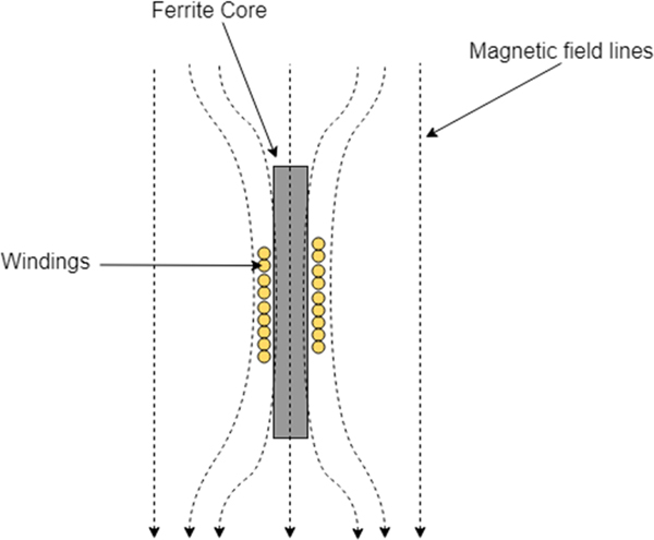
Ferrite-core antennas are commonly used in radio broadcast receivers to boost the antenna gain over a relatively narrow frequency band. The addition of a ferrite core (with suitably large magnetic permeability) has the effect of guiding the magnetic field through the coil windings and increasing flux, as shown in Fig. 1. In the context of WPT, this means a larger magnetic flux passing through the windings leading to greater induced voltage and higher output power. However, to design a WPT system, there are enumerable engineering tradeoffs in the size, shape of both the ferrite-core receiver as well as the transmitter that affect the system efficiency, maximum power level, input/output impedance, cost, etc.
Effect of a ferrite core on a magnetic field.

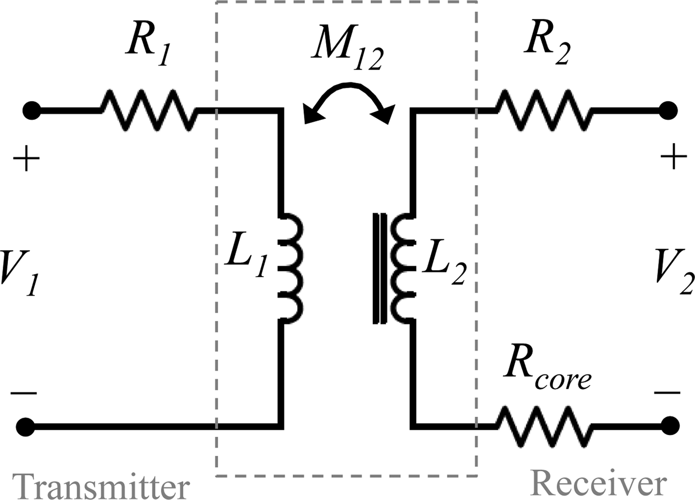
For design purposes, as shown in Fig. 2, a WPT system is typically modeled as a pair of coupled coils using equivalent circuit parameters. Parameters R 1, L 1, and R 2, L 2 represent the resistance and leakage inductance of the primary and secondary windings, respectively. Below the self-resonance frequency, the parasitic self-capacitance of each coil can typically be ignored. From an equivalent circuit perspective, the ferrite core increases the mutual coupling between a transmitter coil and receiver coil, M 12, which is critical for achieving higher power transfer efficiency at longer distances. To first-order approximation, the increase in mutual coupling afforded by a ferrite core is given by [Reference Theilmann and Asbeck7].
 $$\displaystyle{{M_{ferrite-core}} \over {M_{air-core}}} = \displaystyle{{\mu _r} \over {1 + N_D(\mu _r-1)}}.$$
where μ r is the relative permeability of the core, and N D is the shape-dependent demagnetization factor. For a typical value of μ r = 125 and N D = 0.05 (cylinder with 8:1 aspect ratio), the mutual inductance would ideally be improved by a factor of 17.3. However, a drawback of using magnetic cores is that the magnetic core material introduces additional energy dissipation (loss) mechanisms, represented by R core. So while adding a ferrite core can certainly increase the energy coupling between the transmitter and receiver, the additional energy losses can negatively impact the overall end-to-end system power efficiency.
Equivalent circuit representation of an air-core transmitter coil coupled to a ferrite-core receiver coil (below the self-resonance frequencies of the coils).

A primary difficulty of any lumped modeling effort is accurately predicting the equivalent circuit parameter values. The mutual coupling M 12 can be analytically calculated when the coils are axially aligned, but numerical simulations may be required if the transmitter and receiver are rotated or laterally offset from one another. The most difficult parameter to predict a priori is typically the loss in the magnetic core, namely R core. Magnetic core losses include eddy-current loss, hysteresis loss, and anomalous loss, each one dependent on the magnetic material, device structure/shape, and magnetic field amplitude and frequency [Reference Goodenough12, Reference Yan and Ai-ming13].
Theilmann and Asbeck [Reference Theilmann and Asbeck7] presented the earliest analytic model for modeling a (single-turn) transmitter coil and a multi-turn ferrite-core receiver, focusing primarily on how to calculate the self- and mutual inductance of the coils, as well as the core loss. Their model accounts for the real/imaginary permeability of the core (capturing energy storage and energy loss), shape demagnetization, skin effect, and other important parameters. This model is shown to match a range of experiments, but is limited in the following ways: assumes only a single-turn transmitter; requires the transmitter and receiver to be axially aligned; does not calculate any capacitances; and enables calculation of mutual induction and maximum available gain, which informs the maximum possible efficiency, but does not enable direct calculation of actual efficiency (which must account for impedance matching on the source and load side). More recently, Wang et al. [Reference Wang, Feng, Shi and Shen11] presented a similar modeling framework, and under certain assumptions, explicitly calculated the power efficiency based on knowledge of certain model parameters. These and other models can be used to optimize the WPT system.
B) Receiver design and fabrication
In this work, we use a commercial off-the-shelf transmitter, so our design efforts focus primarily on the ferrite-core receiver. Commercially, there are only a limited number of ferrite materials sold in small lot sizes for research purposes, Fair-Rite and Ferroxcube being some common manufacturers. For this work, various NiZn ferrite cores were obtained from Fair-Rite Products Corp. as part of the Antenna/RFID engineering kit (0199000024). This kit includes a variety of ferrite cores of different sizes and material types for R&D purposes.
Of the Fair-Rite materials, Material 61 was selected for having the best material quality factor at the 6.78 MHz operating frequency. Based on the vendor-provided data [14], Material 61 exhibits an initial relative permeability of μ i = 125 and a resistivity of ρ = 108 Ω cm. At the operating frequency of 6.78 MHz, the material quality factor (Q core ≈ μ ′/μ′′) is in excess of 125, and the core power loss density at 10 mT field amplitude is estimated to be 300 mW/cm3.
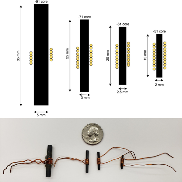
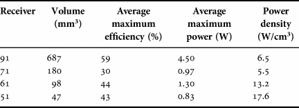
Prior studies have indicated that long, cylindrical cores with low demagnetization are preferred [Reference Theilmann and Asbeck7, Reference Wang, Feng, Shi and Shen11]. As shown in Table 1 and Fig. 3, four different size receivers (all with length to diameter aspect ratio of ~8) were selected for study, denoted −91, −71, −61, and −51 after the last two digits of the product ID of the core. The largest device (−91) used a 5 mm-diameter, 35 mm-long core, whereas the smallest device (−51) used a 2 mm-diameter, 15 mm-long core.
Scale diagrams and photographs of different sized receivers.

Summary of different receivers.

For all four sizes, a self-inductance of ~1.0 µH was targeted, so that the inductor reactance (X L = 2πfL) was in the neighborhood of 50 Ω at 6.78 MHz. Additionally, by maintaining a constant inductance across the different sizes, the same tuning capacitor could be used for all experiments, so as to minimize the number of experimental variables. Coil32 [15], an online calculator, is used to guide the design of the ferrite-core receivers. In this calculator, the user inputs a target inductance, the dimensions of the core, and initial magnetic permeability of the ferrite material, and the software suggests various winding patterns (number of turns, number of layers) for various gauge wires. Using the Coil32 software, the required number of turns for a single-layer winding was calculated to achieve the target inductance. The cores were hand wound with either 19 AWG or 22 AWG solid-core enameled copper wire (winding turns varied from 5 to 10) that was optionally secured with glue.
Coil32 does not calculate the device resistance, capacitance, or self-resonance frequency for cored inductors. However, the DC coil resistance can be easily estimated based on the product of the total winding length and the vendor-reported wire resistivity per unit length, R DC = ρ′L. The AC winding resistance is calculated as R AC = KΨR DC, where K is a skin effect factor and Ψ is a proximity effect factor. At 6.78 MHz, the skin depth in copper is approximately 25 µm. For copper at room temperature, the skin effect factor can be approximated as  ${\rm K}\approx 3.78d\sqrt f $ where d is the wire diameter (in mm) and f is the frequency (in MHz) [Reference Medhurst16, Reference Medhurst17]. Experimentally, 19- and 22-gauge (AWG) wires are used, which have diameters of ~910 and ~600 µm and corresponding K values of 9.0 and 5.9, respectively. The proximity effect factor Ψ for a single-layer, tightly wound, air-core solenoid coil ranges from 3.4 to 5.8 [Reference Medhurst16, Reference Medhurst17], but will differ in the case of a ferrite core. The capacitance and self-resonance of the cored inductor must also be considered, but as will be experimentally shown, at the 6.78 MHz operating frequency, the receivers are operating far below their self-resonant frequency, and because an additional external capacitor is used to tune the total receiver capacitance, the receiver self-capacitance need not be exactly known.
C) Receiver characterization
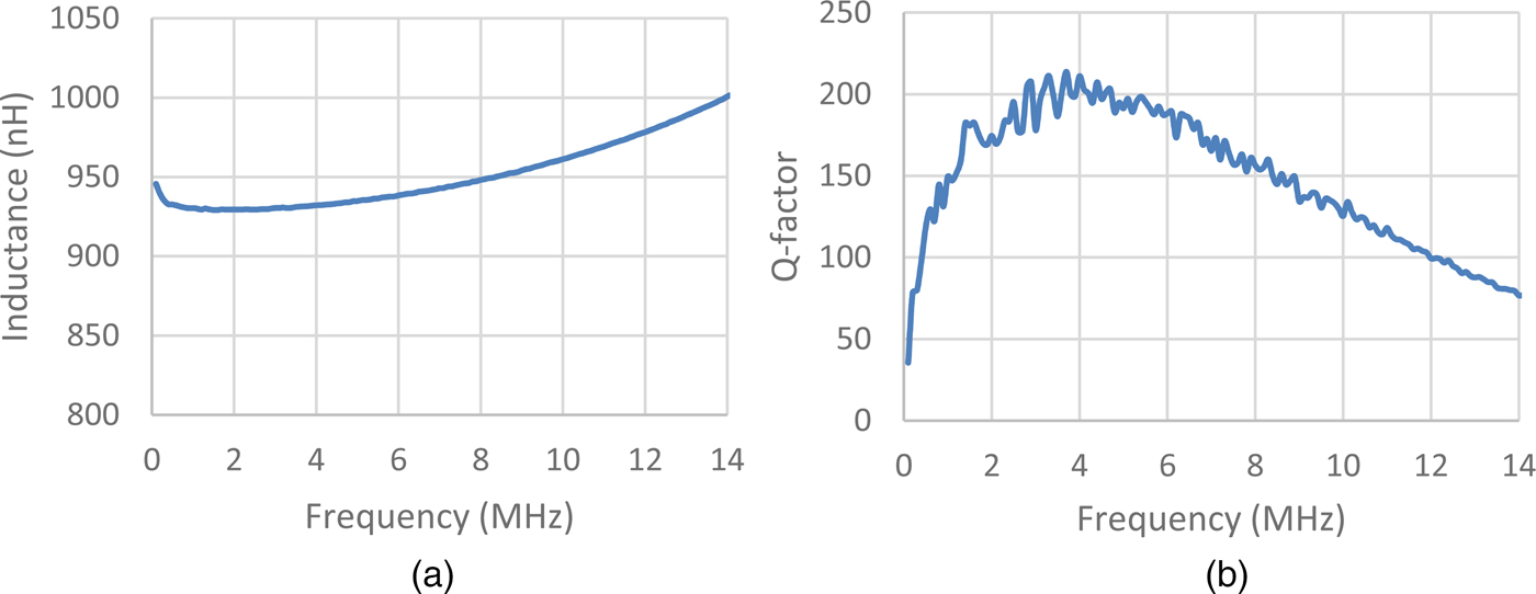
Once fabricated, the terminal impedance of each receiver was characterized using an HP4294A impedance analyzer. Figure 4 shows an example impedance spectrum (L−Q values versus frequency) for the −91 receiver. At 6.78 MHz, the inductance was measured to be 0.94 µH, and the quality factor was measured to be 180, corresponding to an effective AC resistance of 0.22 Ω. These data show the as-fabricated device was very close to the 1 µH target with a very high-quality factor. Compared with other reported values, the Q factor (here Q = ωL/R) of this device was substantially higher than those reported in [Reference Theilmann and Asbeck7, Reference Carta, Thoné and Puers10], but about half of the value of the devices reported in [Reference Cook, Sieber, Widmer and Schwaninger5, Reference Cook, Schwaninger and Widmer6], which used Litz wire. High Q factor is attributed to the relatively few number of winding turns (low conduction loss) and also operating the device near the peak operating frequency of the magnetic core material (low magnetic core loss). The other receivers were similarly tested, with Table 1 summarizing the results.
Measured (a) inductance and (b) Q-factor of −91 receiver.

One observation is that the smaller devices required more turns, which is accompanied by higher DC resistance and lower Q factor. Table 1 also tabulates the measured AC resistance at 6.78 MHz. This AC resistance accounts for both winding and core losses. Here the AC resistances are seen to range from 31× to 142× larger than the DC coil resistance. Skin and proximity effects in the windings can likely only account for a maximum increase of about 50×, meaning core losses are indeed playing a significant role in the overall energy loss.
III. WIRELESS POWER EXPERIMENTS
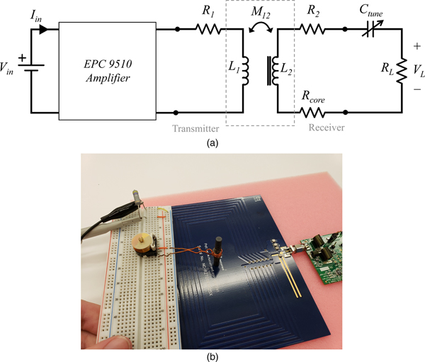
Experiments were primarily focused with evaluating the performance of the receivers in terms of maximum power transmission level and efficiency. Figure 5 shows a simple schematic representation and photograph of the WPT system testing. In all experiments, the transmitter used was part of a commercially available demo kit from Efficient Power Conversion (EPC9114), which is designed to meet the Rezence (now known as the Air Fuel Alliance) wireless charging standard [18]. The transmitter uses a zero-voltage-switching class-D RF power amplifier to drive a printed-circuit board transmitter coil to create a magnetic field at 6.78 MHz. On the receiver side, a tuning capacitor C tune and resistive load R L were connected in series to the output terminals of the receiver. The resistive loads in all experiments were discrete 2 W, 5% tolerance, metal-oxide power resistors. The 150 V, 25–600 pF tuning capacitor was manually trimmed to excite resonance in the receiver. All circuit components were mounted to a breadboard for testing.
(a) System circuit diagram and (b) experimental setup using the EPC9114 transmitter with the −91 ferrite-core receiver.

The input power was calculated as P in = V inI in, where V in and I in were the DC voltage and current, respectively, fed to the amplifier circuit, directly measured via the laboratory power supply. The output power to the load resistor was assessed by using an oscilloscope to measure the RMS voltage V L across the load, with output power calculated as  $P_{out} = V_L^2 /R_L$. The load resistance R L of each load was taken as the marked value on each component. It was assumed that the load resistance did not significantly change with current/temperature during the experiments. The Yageo RSF series resistors used are rated to undergo minimal (±1.0%) changes in resistance for short overload periods at up to 2.5 times the rated continuous working voltage. The RMS V across a resistor never exceeded this value. System power efficiency was calculated by dividing the output power by the input power, i.e. η = P out/P in.
A) Maximum power performance
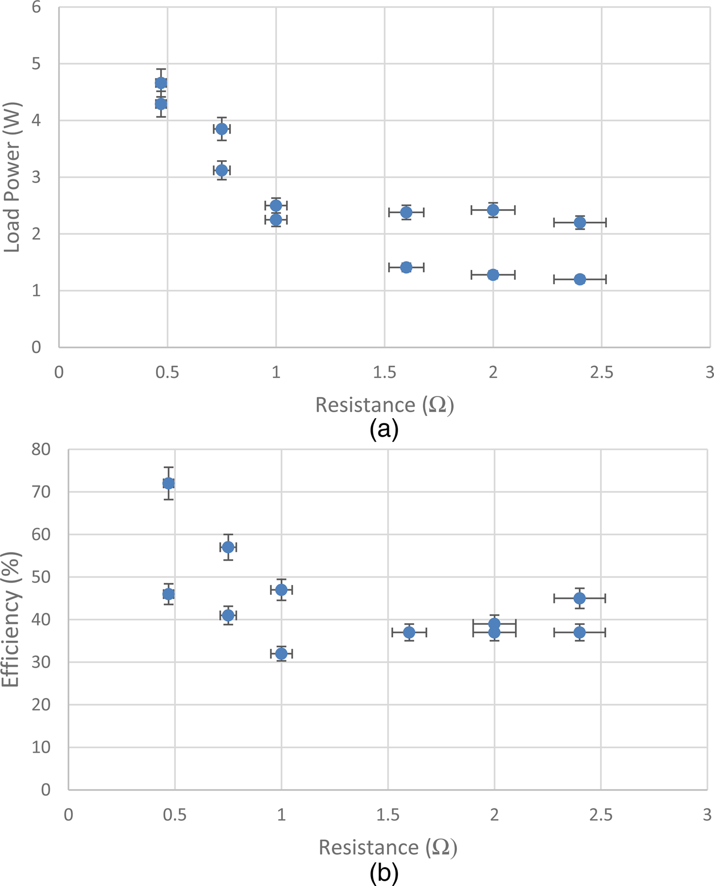
Initial testing was performed with the −91 receiver, with the ferrite core vertically oriented (ideal position) and centered and in contact with the transmitter coil (as shown in Fig. 5). To determine the maximum power that the receiver could harvest from the transmitter, a range of load resistances were tested to determine the ideal load resistance. Power and efficiency measurements across a small range of low-resistance values are shown in Fig. 6. The measurement uncertainties (error bars represent 95% confidence intervals) are primarily attributed to the resistor tolerance. The load power and efficiency both increased with decreasing load resistance. A maximum power of 4.7 W was measured with an efficiency of 72% for a load resistance of 0.5 Ω. The 0.5 Ω load was the smallest reliable load that could be tested, since smaller loads were subject to parasitic resistances from the connecting wires and breadboard connections. For all loads ranging from 0.5 to 2.5 Ω, the system efficiencies were typically above 40%.
(a) Output power and (b) system efficiency versus load resistance for the −91 receiver.

For a receiver this size, a maximum power draw of 4.7 W with an efficiency in the 50% range is significant. This power draw is within the range of many common mobile devices including modern smart phones. Additionally, it experimentally demonstrates that ferrite receivers are capable of drawing multiple watts of power at relatively high-efficiency levels despite the additional loss mechanisms introduced by magnetic materials.
B) Effect of receiver location
Tests concerning how a ferrite-core receiver was able to perform in different locations relative to the transmitter were also conducted. Given the large difference in geometry between the transmitter coil and receiver, it is important to understand how the smaller receiver would perform when not centered or resting on the transmitter. While resonant systems do offer an improved range when compared with inductive systems, harvested power and transmission efficiency still decrease significantly with transmission distance. Here a 1.0 Ω load resistor was used with the −91 receiver.
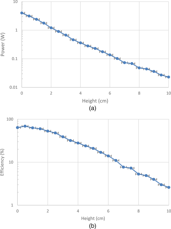
Figure 7 shows the load power and efficiency while keeping the receiver centered, but moving it away from the transmitter antenna up to a maximum height of 10 cm. The height is measured from the bottom of the ferrite core to the receiver (i.e. the air gap). A 1.0 Ω resistor was used as a load. Over the range tested, the load power declined exponentially with height. A linear fit to the semi-log function results in a slope of approximately −0.24. Efficiency also declined, but at a non-constant scaling. It is worth noting the datasheet for the EPC9114 transmitter does not explain how the transmitter power is regulated in response to the load position. Nevertheless, the receiver was still able to draw a power of 1 W at >50% efficiency at a height of 2.0 cm, and 100 mW at >10% efficiency at 6.5 cm.
(a) Output power and (b) system efficiency for the −91 receiver at different heights above the transmitter.

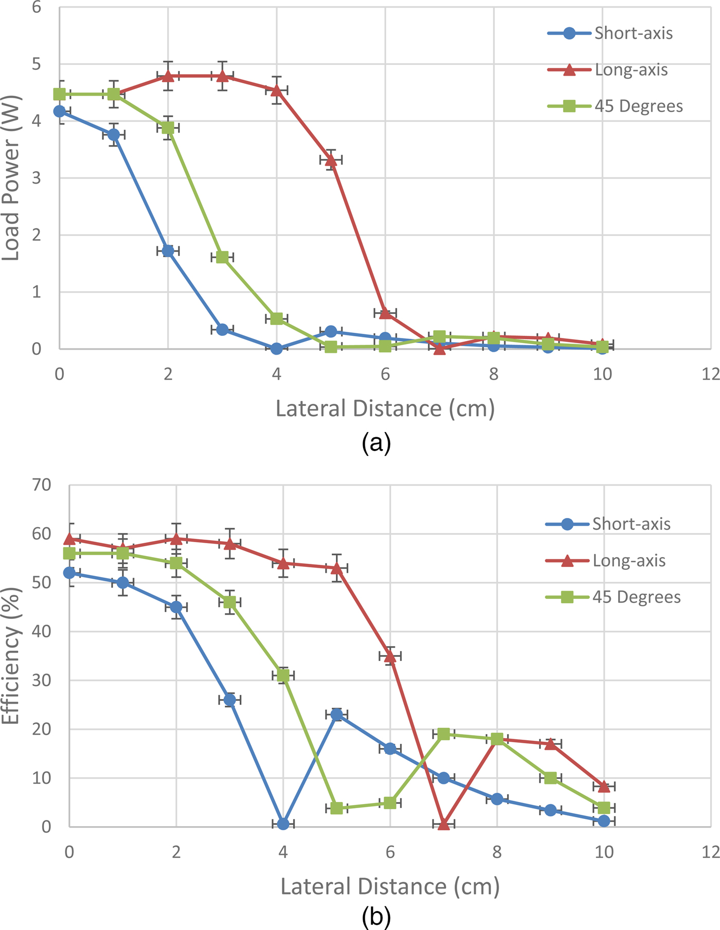
Receiver performance was also evaluated as a function of lateral distance from the center of the transmitter with the receiver in contact with the transmitter. In these tests, receiver power performance was evaluated as it was moved away in 1 cm increments from the center of the transmitter with a height (gap) of zero. The transmitter coil uses rectangular shape windings, with the outermost windings measuring 9 cm × 15 cm and the innermost windings measuring 4 cm × 10 cm. Starting from the center, lateral offsets in three different directions were explored: along the long-axis of the transmitter, along the short-axis of the transmitter, and at a 45° angle in between. Here the −91 receiver with a 0.47 Ω load resistor was used.
Figure 8 shows the measurement results. Load power remained high so long as the receiver was within the center region of the transmitter, but decayed rapidly after moving beyond the innermost windings. Power at the outermost edges of the transmitter windings was approximately only 5% of the maximum measured power inside of the center winding. Moving beyond the outermost windings, the power was negligible. The use of the ferrite-core receiver facilitates relatively broad lateral freedom, allowing high power and efficiency, so long as the receiver is positioned within the extents of the transmitter windings. Systems such as biomedical implants may be able to take advantage of these lateral degrees of freedoms.
(a) Output power and (b) system efficiency of the −91 receiver at different lateral offset locations.

C) Performance of different receiver sizes
Additional experiments were conducted to assess the performance of receivers that made use of smaller cores. As integrated electronics get smaller and smaller, more compact wireless power receivers are highly desirable, especially for applications where mass and volume are critical.
For this set of experiments, the receivers were placed in the middle of the transmitter antenna, oriented perpendicular (aligned with the field), and set in contact with the receiver (zero gap). The systems were first tuned using the trimmer capacitor and tested across a range of load resistances to evaluate power draw and system efficiency. For each of the smaller receivers (−71, −61, and −51), three measurements were taken for each load resistance.
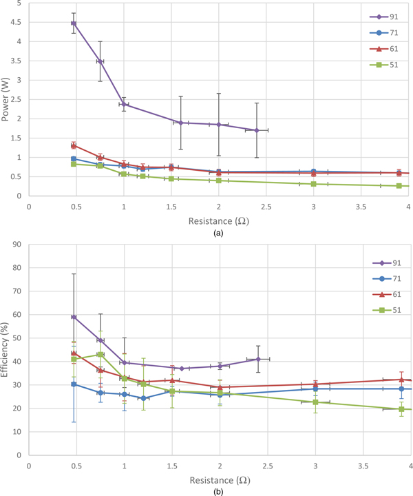
Load power and efficiency data are shown in Fig. 9, with comparison to the larger −91 receiver. Across the range of load resistances tested, the larger receivers tended to outperform the smaller ones in terms of power draw and efficiency. However, at maximum power, the smaller receivers generally exhibited larger power densities, as summarized in Table 2. There was much greater trial-to-trial variance observed at lower load resistances in both power and efficiency, possibly due to miniscule differences in tuning that become more pronounced under matched-load conditions.
(a) Output power and (b) system efficiency versus load resistance for different receivers.

Comparison of size and performance of receivers of differing sizes.

IV. CONCLUSION
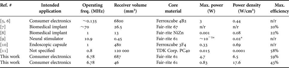
In this paper, we have presented experimental results of using ferrite-core antennas for WPT. It was demonstrated that solenoid-shaped antennas can receive multiple watts of power with >50% efficiency from a commercially available WPT demo board operating at 6.78 MHz. Smaller receivers (46 mm3) are shown to achieve a higher power density (up to 17.6 W/cm3) compared with larger receivers (687 mm3, 6.5 W/cm3). Table 3 summarizes the results presented in this paper compared with several other previously reported ferrite-core wireless power receivers. The power levels, efficiencies, and exceptionally high-power densities achieved here are significantly larger than the comparison devices, although some of the comparison biomedical devices may have been power constrained by maximum allowable field levels for human exposure. Most notably the work here demonstrates a receiver power density that is 25× higher than the best-reported ferrite-core receiver (17.6 versus 0.69 W/cm3).
Comparison of this work with selected devices from other reported literature.

n/r, not reported.
*Estimated from data in the paper.
Overall, the ferrite-core devices offer a size reduction and a more compact form-factor compared with traditional air-core planar receivers, affording potential high-energy density wireless power delivery to consumer electronics such as smart phones and tablets, as well as smaller devices such as wearables, hearables or possibly implantables. Further work is required to optimize such devices, but the preliminary results indicate that WPT receivers using ferrite cores are worthy of further development for a variety of applications.
ACKNOWLEDGEMENTS
The authors thank John Varela, Nicolas Garraud, Dr. Alexandra Garraud, and Daniel Alabi for their valuable guidance and suggestions in the experimental measurements.
FINANCIAL SUPPORT
This work was supported in part by the NSF I/UCRC on Multi-functional Integrated System Technology (MIST) Center (NSF Grant IIP-1439644) as well as internal support from the University of Florida Office of Technology Licensing.
CONFLICT OF INTEREST
None.
ETHICAL STANDARDS
Not applicable.
 Stasiu T. Chyczewski is currently working on his B.S. in Electrical Engineering at the University of Florida (2020). His current research interests include wireless power systems.
 Seahee Hwangbo received her B.S. degree from Gangneung-Wonju National University, Gangneung-si, Republic of Korea, in 2012, and is currently pursuing her Ph.D. degree in Electrical and Computer Engineering at the University of Florida, Gainesville, FL, USA. Her current research interests include micro/nanofabrication, RF MEMS, RF/Microwave passive components, 5G/millimeter-wave (mm-wave) antennas for wireless chip-to-chip communications in 3D-System in Packaging (3D-SiP), and low RF loss conductors for 28 GHz 5 G applications. She won second place in 2017 International Microwave Symposium (IMS) Student Paper Competition and the IEEE Antennas and Propagation Society (AP-S) Doctoral Research Award in 2016.
 Yong Kyu Yoon received his Ph.D. degree in Electrical and Computer Engineering from the Georgia Institute of Technology, Atlanta, GA, USA in 2004. He is currently an Associate Professor of the Department of Electrical and Computer Engineering at the University of Florida, Gainesville, Florida, USA. He received the NSF Early Career Development Award (CAREER) and SUNY Young Investigator Award. He has more than 180 peer-reviewed publications. He is a member of IEEE society. His research interests include microelectromechanical systems, nanofabrication, and energy storage devices; metamaterials for RF/microwave applications; micromachined millimeter wave/terahertz antennas and waveguides; wireless telemetry systems for biomedical applications; and ferroelectric materials for memory and tunable RF devices.
 David P. Arnold received dual B.S. (1999) and M.S. degrees (2001) from the University of Florida and the Ph.D. degree in Electrical and Computer Engineering from Georgia Tech (2004). He is currently the George Kirkland Engineering Leadership Professor in the Department of Electrical and Computer Engineering, Deputy Director of the NSF Multi-functional Integrated System Technology (MIST) Center, and Director of the Interdisciplinary Microsystems Group at the University of Florida. His research focuses on micro/nanostructured magnetic materials, magnetic microsystems, electromechanical transducers, and miniaturized power/energy systems. He has co-authored over 170 refereed journal and conference publications, and holds 16 US patents.