Introduction
Many emerging photonics and optoelectronics applications require them to be directly triggered or tuned by mechanical inputs from their environment. Some inorganic or organic materials exhibit light emission when an external mechanical stimulus is applied, which is termed mechanoluminescence (ML). Xu first reported intense and reproducible luminescence during exposure of certain materials to mechanical stimuli, including ZnS:Mn2+ and SrAl2O4:Eu2+, and introduced the principle and applications of hybrid inorganic–organic composites especially for sensors and sensitive artificial skins.Reference Xu, Watanabe, Akiyama and Zheng1–Reference Xu and Schwartz3 Wang introduced the field of piezophotonics in semiconductors, regarded as a two-way coupling of piezoelectric–photoexcitation.Reference Wang4,Reference Wang5 Therefore, metal ions as activators in ML may serve for demonstrating the piezophotonic effect since they are capable of responding to photoexcitation and subsequently emitting light.
Luminescence is a phenomenon in which the excitation energy of a substance excited by external energy is given off as a photon, resulting in light emission. One may classify luminescence according to the excitation source used. Typically, photoluminescence (PL) is stimulated by photon energy while electroluminescence (EL) is triggered by an electric field. PL- and EL-based materials have been extensively applied in display systems, light-emitting diodes (LEDs), solid-state lighting, and biomedicine.Reference Bai, Tsang and Hao6,Reference Bai, Tsang and Hao7 A useful form of ML, elasticoluminescence (ESL), recoverable light emission generated during elastic deformation that is also called piezoluminescence for piezoelectric materials, has attracted considerable attention because it can be repeatedly used for mechano-optical conversion. ESL materials and devices offer advantages of wireless detection and nondestructive analysis, making it a promising candidate for various applications such as stress sensing and damage diagnosis.Reference Matsui, Xu, Liu and Tateyama8–Reference Li, Xu, Tu, Chai, Wang, Liu and Kawasaki13
Here, we first introduce the physical mechanisms of piezo-photonics, followed by the relevant materials considerations and processing. We review the development of recent prototypical demonstrations and applications. Finally, a brief perspective on piezophotonics is outlined.
Fundamental principles and materials considerations
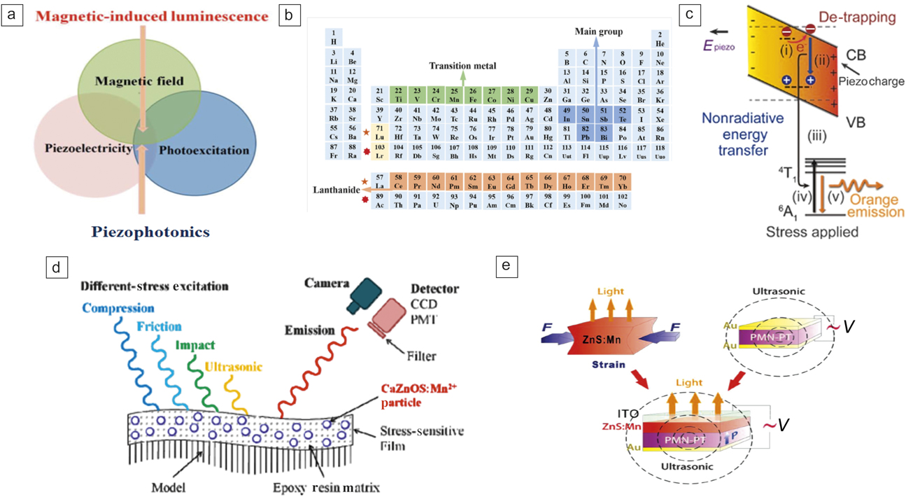
The piezophotonic effect is a two-way coupling between piezoelectricity and photoexcitation properties as shown in Figure 1a.Reference Wong, Chen, Tsang, Zhang and Hao14 The piezophotonic effect uses the piezopotential to tune the energy band, carrier detrapping, and recombination and hence induces photon processes such as light emission. Apart from the two-way coupling effect mentioned, coupling between other external stimuli and the piezophotonic effect can lead to additional physical effects. As an example, magnetic-induced luminescence (MIL), shown in Figure 1a, is observed via strain-mediated coupling, which will be described in the subsequent section.
(a) Schematic showing the coupling for piezophotonics and magnetic-induced luminescence.Reference Wong, Chen, Tsang, Zhang and Hao14 (b) Metal ions in piezophotonic materials.Reference Bai, Tsang and Hao6 (c) Energy diagram showing the piezophotonic effect-initiated luminescence in ZnS:Mn.Reference Wang, Zhang, Yu, Dong, Peng, Zhang, Zhang, Liu, Pan and Wang21 (i) Detrapping of electrons is facilitated by strain-induced piezopotential. (ii) Nonradioactive recombination occurs between these detrapped electrons and holes. (iii) Transfer of energy to Mn2+ ions. (iv) Excited Mn2+ ions fall back to the ground state with (v) the emission of visible light. (d) Ultrasonic-, impact-, tribo-, and compression-luminescence of CaZnOS:Mn2+ polymer films.Reference Zhang, Xu, Kamimura, Terasawa, Yamada and Wang12 (e) Dual-mode emission of piezophotonic luminescent and ultrasonic waves from ZnS:Mn film grown on Pb(Mg1/3Nb2/3)0.7Ti0.3O3 (PMN-PT) under an AC electric field.Reference Zhang, Gao, Chan, Dai, Wang and Hao18 Note: ITO, indium tin oxide; E piezo, piezoelectric potential inside the phosphor crystal lattice induced from external pressure; F, force applied to the ZnS:Mn phosphor; PMT, photomultiplier tube; CCD, charge-coupled device; 4T1 and 6A1, positron energy levels of Mn2+ ions when it doped in a II–IV semiconductor; CB, conduction band; VB, valence band; V, voltage.

Figure 1b shows commonly used luminescent ions in a periodic table.Reference Bai, Tsang and Hao6 Two classes of metal ions are mainly used as activators for piezophotonics, lanthanide (Ln) ions and transition-metal (TM) ions. The luminescence of Ln and TM ion-doped phosphors can cover a broad optical spectral range, including ultraviolet, visible, and infrared regions.Reference Bai, Tsang and Hao6 Ln ions, including Pr3+, Sm3+, co-doped Ce3+ and Ho3+, and Eu2+ have been used in ESL phosphors.Reference Botterman, Eeckhout, Baere, Poelman and Smet9,Reference Tu, Xu, Yoshida, Fujihala, Hirotsu and Zheng11,Reference Kamimura, Yamada and Xu15–Reference Liu and Xu17 Because of the larger spatial extension of the spectroscopically active d electrons, the energy-level structures of TM ions are sensitive to their coordination environment associated with external perturbations, such as mechanical strain. To date, TM ions such as Mn2+, Cu+, and co-doped Mn2+ and Cu+ have been used by different groups.Reference Zhang, Xu, Kamimura, Terasawa, Yamada and Wang12,Reference Wong, Chen, Tsang, Zhang and Hao14,Reference Zhang, Gao, Chan, Dai, Wang and Hao18–Reference Wang, Zhang, Yu, Dong, Peng, Zhang, Zhang, Liu, Pan and Wang21
Using the typical example of ZnS:Mn, the fundamental principle of light emission under mechanical stress is shown in Figure 1c. An imposed stress gives rise to a piezopotential in wurtzite-structured ZnS, which tilts the bands of ZnS. The detrapped electrons at the defect states can then escape to the conduction band, followed by the nonradiative recombination of electrons and holes. The released energy excites the Mn2+ dopant ions, and photon emission occurs when the excited Mn2+ ions return to the ground state.Reference Wang, Zhang, Yu, Dong, Peng, Zhang, Zhang, Liu, Pan and Wang21,Reference Zhang, Jie, Chen, Liu and Hao22
Currently, luminescent metal ion-doped hosts have been fabricated in different forms, including crystals, powders, nanowires, nanoparticles, and thin films. Figure 1d displays the ultrasonic-, impact-, tribo- and compression-luminescence of CaZnOS:Mn2+ polymer films under different types of stress excitation.Reference Zhang, Xu, Kamimura, Terasawa, Yamada and Wang12 A method of controllable piezoelectric-induced strain from Pb(Mg1/3Nb2/3)0.7Ti0.3O3 (PMN-PT) has been developed, which has been used for piezophotonics. With this novel technique, dual-mode emissions can be generated and modulated precisely (Figure 1e).Reference Zhang, Gao, Chan, Dai, Wang and Hao18 Through dual-mode emissions, light and ultrasound waves can be simultaneously generated from a single system. One can tune the luminescence and ultrasound signal from this system via a converse piezoelectric effect in PMN-PT upon the application of either an AC or a DC electric field. Recently, Fang et al. monolithically integrated a triboelectric nanogenerator with a mechanoluminescent film.Reference Fang, Wang, Li, Peng, Yan and Pan23 These approaches utilize readily available ambient mechanical energy to generate either electrical or light output. The pursuit of multifunctionality has become a new important trend in recent years and such devices promote the development of smart systems to efficiently utilize mechanical energy in many ways and demonstrates great potential for a variety of applications.
Recent prototypical demonstrations and applications
Recently, there has been a trend to apply piezophotonic materials to demonstrate interesting multifunctional applications. This section briefly describes select examples of the latest research in this field. Generally, it is still difficult to predict and quantify the risk level of fracture by stress/strain concentration for fabricated structures with microstrains below 1000 μst (1 μST = 10–6 strain) using conventional ESL materials. Therefore, it is important to develop novel materials with thresholdless high sensitivity and quantify emission intensity for microstrains.
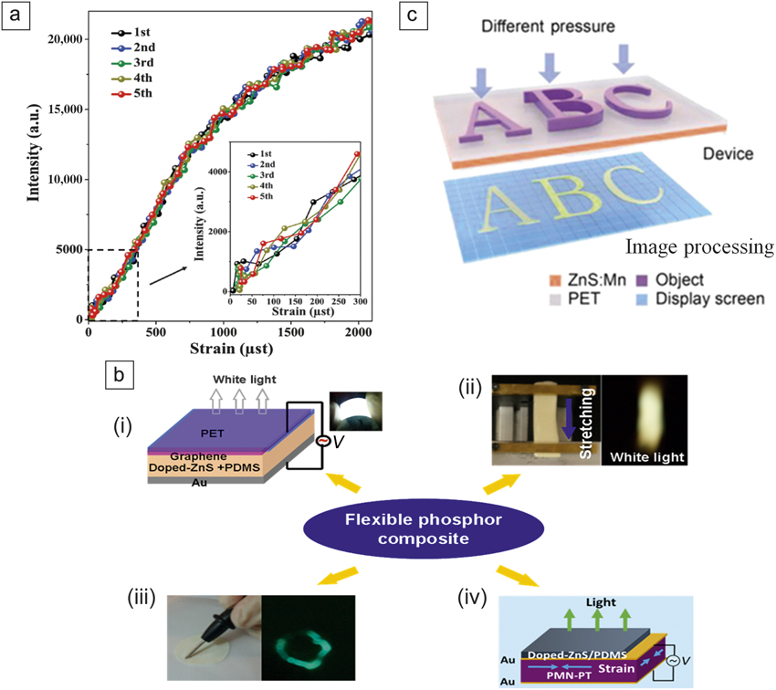
Recently, a high-performance piezo-multifunctional material named as “multi-piezo” has been found that exhibits both piezoelectricity and efficient luminescence.Reference Tu, Xu, Yoshida, Fujihala, Hirotsu and Zheng11 The study was performed by doping lanthanide Pr3+ ions into a LiNbO3 host by precisely tuning the Li/Nb ratio in nonstoichiometric LiNbO3:Pr3+, a material that exhibits a high luminescence intensity. Figure 2a shows the light emission of a LiNbO3:Pr3+ sheet during tensile strain tests. In particular, LiNbO3:Pr3+ shows excellent strain sensitivity at the lowest strain levels, with no threshold for stress sensing, as shown in the inset of Figure 2a. These multiple piezoproperties are useful for multifunctional device applications. As previously discussed, it is interesting that a PMN-PT actuator used to produce piezopotential demonstrated the piezophotonic effect. In addition to the earlier study on proving the piezophotonic effect by this strategy,Reference Zhang, Gao, Chan, Dai, Wang and Hao18 composite-based hybrid devices have been further developed that are capable of sensing different types of external stimuli, including electric fields, uniaxial strains for stretching and mechanical writing, and piezoelectric biaxial strain (Figure 2b).Reference Chen, Wong, Bai, Jie and Hao24
(a) Mechanoluminescence (ML) response of the LiNbO3:Pr3+ sheet. The inset shows the mechanoluminescence response of the sheet in the strain range from 0 to 300 μst, where the unit μst (microstrain) = 10–6 strain.Reference Tu, Xu, Yoshida, Fujihala, Hirotsu and Zheng11 The ML curves showed excellent reproducibility during the five strain cycles. Meanwhile, LiNbO3:Pr3+ exhibits a much higher piezoluminescence intensity, which far exceeds other piezoluminescence materials such as CaZnOS:Mn, ZnS:Mn, and ZnS:Cu.Reference Zhang, Xu, Kamimura, Terasawa, Yamada and Wang12,Reference Chen, Wong, Bai, Jie and Hao24 (b) Composite phosphors and devices for sensing different types of external stimuli. (i) Structure of the device. The inset shows a photograph of the white light emission of the device biased at 100 V and 1 kHz. (ii) (Left) Sample mounted on the stretch-release system and (right) the corresponding white light emission from the sample. (iii) (Left) Photograph of sample under mechanical writing and (right) green ML emission under mechanical writing. (iv) Schematic of the piezophotonic luminescence device.Reference Chen, Wong, Bai, Jie and Hao24 (c) Schematic of the pressure mapping process by the piezophotonic effect.Reference Wang, Ling, Zhang, Que, Peng and Pan26 Note: PET, poly(ethylene terephthalate); PDMS, poly(dimethylsiloxane); PMN-PT, Pb(Mg1/3Nb2/3)0.7Ti0.3O3; V, voltage.

Zhang et al. recently presented addressable and color-tunable piezophotonic light-emitting stripes by replacing the PMN-PT crystal with piezoelectric films. Each actuator can be manipulated independently, offering an opportunity to control the light emission in a single pixel.Reference Chen, Zhang, Karnaushenko, Chen, Hao, Ding and Schmidt25 Interestingly, the Pan group demonstrated a pressure sensor matrix composed of poly(dimethylsiloxane) mixed with ZnS:Mn ML phosphor.Reference Wang, Zhang, Yu, Dong, Peng, Zhang, Zhang, Liu, Pan and Wang21,Reference Wang, Ling, Zhang, Que, Peng and Pan26 Figure 2c shows a schematic of the pressure mapping process using the piezophotonic effect.Reference Wang, Ling, Zhang, Que, Peng and Pan26 The dynamic pressure mapping device promises prospective applications in real-time pressure sensing and three-dimensional handwriting.
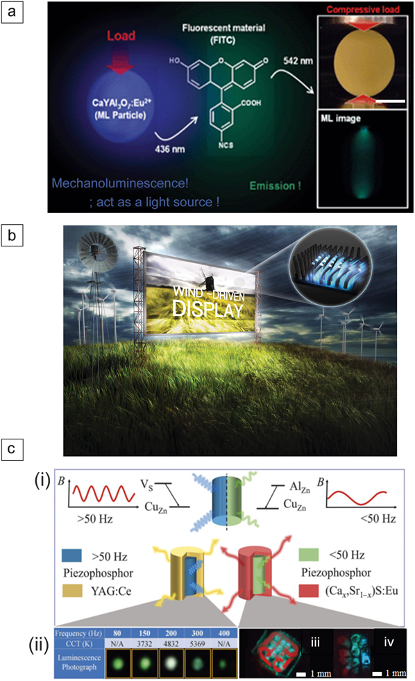
Apart from stress-optical sensing, materials have been explored for other emerging applications.Reference Peng, Chen and Wang27 Figure 3a illustrates a ML light source for a fluorescent probe molecule in bioimaging and phototherapy, even in the dark environment inside biotissues.Reference Terasaki, Zhang, Yamada and Xu28 A light source induced by ultrasonic waves was also demonstrated for photo-activation of TiO2 photocatalyst.Reference Terasaki, Yamada and Xu29 Jeong et al. reported a wind-driven device that is capable of emitting warm/neutral/cool white light from Cu-doped ZnS-based composites.Reference Jeong, Song, Joo, Kim, Hwang, Jeong and Kim20 Such novel displays/lighting systems could pave the way to new environmentally friendly lighting, reducing energy waste and promoting sustainability (Figure 3b).
(a) Mechanoluminescence (ML) light source for a fluorescent probe molecule in a potential biological application.Reference Terasaki, Zhang, Yamada and Xu28 Inset images are the photographs before and during application of a load on the pellet, which consists of blue ML particles of CaYAl3O7 with grain size of ca. 1 μm. Upper image was taken with lighting before application of the load, while the lower image was recorded during application of the load without light. The fluorescence material of FITC was excited by the ML light source. (b) Conceptual image of a wind-driven ML device that produces significant brightness and emits light over a range of tunable white color. The inset demonstrated patterned, colorful ML driven by wind.Reference Jeong, Song, Joo, Kim, Hwang, Jeong and Kim20 (c) Full-color display by temporal and remote tuning of piezophotonic-effect-induced color gamut from a piezo-phosphor (ZnS:Al,Cu) coupled with other phosphors. (i) The red curves indicate the instantaneous magnetic flux (B) though the magnetic-induced luminescence (MIL) sample in (left) low and (right) high frequency regimes. Donor (Vs,AlZn) and acceptor (CuZn) states are created when specific metal ions are doped into the host piezophosphor lattice. Under a strain-induced piezo-potential, electron detrapping occurs, and electrons recombine with holes in the CuZn acceptor levels, resulting in MIL emission. (ii) Photographs of white emission with tunable color temperature (CCT) under different modulation frequencies of the magnetic field from a MIL composite mixed with cerium-doped yttrium aluminum garnet (YAG:Ce) phosphor. (iii) The red and green MIL emission of a multicolor MIL flexible composite combined with (Cax Sr1−x)S:Eu displaying the logo of The Hong Kong Polytechnic University. (iv) A display of red-green blue MIL emission.Reference Wong, Chen, Bai, Huang and Hao31 Note: CCT, correlated color temperature; FITC, fluorescein isothiocyanate isomer-I.

Compared to PL and EL, the realization of light emission stimulated by magnetic fields faces a great challenge and the phenomenon of intrinsic MIL is extremely rare. The Hao group first proposed a strategy to observe MIL by coupling the magnetic effect to the piezo-photonic effect,Reference Wong, Chen, Tsang, Zhang and Hao14,Reference Graydon30 as shown in Figure 1a. Most recently, remote and temporal tuning of luminescence was also demonstrated. Tuning is achieved by modulating the frequency of magnetic-field excitation at room temperature, where the emission spectrum from the phosphors in magnetic sensitive flexible composites can be reversibly controlled in real time and in situ. Based on this intriguing property, proof-of-concept devices, including tunable white-light and red-green-blue full-color displays, were fabricated, and they demonstrated promising opportunities for numerous applications, as shown in Figure 3c.Reference Wong, Chen, Bai, Huang and Hao31
Conclusion
Piezophotonics has attracted much attention because it could find broad applications in. multidimensional scale platform applications in fields of earthquake prediction, stability testing of large infrastructures via nondestructive measurements, wearable hand-input oriented multitouch technology in smartphones or other mobile devices with mechanoluminescence that is based on electronics or magneto-stimulation, as well as paving the way for new, environmentally friendly lights or displays.Reference Bai, Yuan, Zhao, Yang, Choi, Chai, Yu, Lau and Hao32 By manipulating the strain and piezopotential of composite phosphors, many devices could be conceived and fabricated based on the principle of piezophotonics. Despite encouraging progress, there are still many issues that remain to be addressed. It is vital to investigate the effects of the piezopotential on optical processes to deepen our fundamental understanding of this phenomenon. Although the coupling between piezoelectricity and photoexcitation in existing materials is promising for device characteristics, it is essential to understand the generalized energy-conversion mechanisms, as a better understanding of the mechanism will be beneficial for establishing guidelines for developing novel ML materials. Meanwhile, further enhancing the energy of ML materials gained from external mechanical stimulation from a variety of sources is also highly feasible. Examples of such sources include the efficient conversion of mechanical stimulation into energy for emitting photons, or an extended decay time of the mechanoluminescent emission to increase the illumination duration. Both indicate promising applications using novel ML technology. It is essential to understand the generalized energy-conversion mechanisms and then enhance energy gain in diverse systems.Reference Xu, Watanabe, Akiyama and Zheng1,Reference Matsui, Xu, Liu and Tateyama8,Reference Huang, Sun and Peng33 Considering their superior flexibility and mechanical strength, optical properties of new two-dimensional (2D) piezo-optical materials are expected to become increasingly important in developing ultrathin and flexible devices. The ultrathin nature of 2D material gives rise to excellent optical transparency and a fast response to external stimulation. Therefore, for 2D piezo-optical materials possessing superior semiconductor properties, the coupling between semiconductor properties and piezoelectricity may help facilitate a new class of ML devices with unusual characteristics.Reference Bai, Yuan, Zhao, Yang, Choi, Chai, Yu, Lau and Hao32–Reference Liu, Xu, Yoshida, Tu, Ueno and Kainuma39 Finally, experimental methods and protocols need to be developed for characterizing the piezophotonic effect and quantifying the properties of relevant materials and device systems. As piezophotonics are a result of three-way coupling among piezoelectricity, mechanical excitation, and semiconductor transport. A common standard is thus required to quantify the performance of these relevant systems so that their outputs can be compared and evaluated. This would be beneficial for establishing guidelines and a roadmap for developing and synthesizing novel ML materials.
Acknowledgments
J.H. acknowledges support from the Research Grants Council of Hong Kong (GRF No. PolyU 153281/16P) and NSFC (Grant No. 11474241). C.N.X. is grateful for support by JSPS KAKENHI (Grant Nos. 25249100, JP16F16076, JP17H06374, and 18H01453).

Jianhua Hao is a professor and associate head of the Department of Applied Physics at The Hong Kong Polytechnic University (PolyU), Hong Kong. Prior to joining the faculty at PolyU, he worked at The Pennsylvania State University, the University of Guelph, Canada, and the University of Hong Kong. He obtained his BSc, MSc, and PhD degrees at Huazhong University of Science & Technology, China. He has published more than 240 scientific papers. His research interests include metal-ion-doped luminescent materials, functional thin films and heterostructures, piezo-photonics and nanoenergy. Hao can be reached by email at jh.hao@polyu.edu.hk.

Chao-Nan Xu is a principal research manager and leader of the research team at the National Institute of Advanced Industrial Science and Technology (AIST), Japan, where she was the founding chair of the Mechanoluminescence Technology Consortium. She has been a concurrent professor at Kyushu University, Japan, since 2005, and also serves as the director of the Electronic Division of The Ceramic Society of Japan (CerSJ). She is the pioneer and inventor on novel mechanoluminescence and their applications and holds more than 150 patents. Her awards include the CerSJ Fellow Award and Distinguished Researcher of the MEXT Minister Prize. Xu can be reached by email at cn-xu@aist.go.jp.