1. INTRODUCTION
Laser-driven plasma acceleration using high-amplitude laser wakefields is promising to make compact accelerators (Tajima & Dawson, Reference Tajima and Dawson1979). A few recent work demonstrated the generation of quasi-monoenergetic electron beams by an ultra-intense laser pulse (Mangles et al., Reference Mangles, Murphy, Najmudin, Thomas, Collier, Dangor, Divall, Foster, Gallacher, Hooker, Jaroszynski, Langley, Mori, Norreys, Tsung, Viskup, Walton and Krushelnick2004; Reference Mangles, Walton, Najmudin, Dangor, Krushelnick, Malka, Manclossi, Lopes, Carias, Mendes and Dorchies2006; Geddes et al., Reference Geddes, Toth, van Tilborg, Esarey, Schroeder, Bruhwiler, Nieter, Cary and Leemans2004; Faure et al., Reference Faure, Glinec, Pukhov, Kiselev, Gordienko, Lefebvre, Rousseau, Burgy and Malka2004; Glinec et al., Reference Glinec, Faure, Pukhov, Kiselev, Gordienko, Mercier and Malka2005; Chen et al., Reference Chen, Unick, Vafaei-Najafabadi, Tsui, Fedosejevs, Naseri, Masson-Laborde and Rozmus2008). However, the electron injection is basically a nonlinear process, which causes poor reproducibility. How to inject electrons into the acceleration phase of the laser wakefield in a controlled way is crucial. To get this, a few injection schemes have been proposed (Umstadter et al., Reference Umstadter, Kim and Dodd1996; Esarey et al., Reference Esarey, Hubbard, Leemans, Ting and Sprangle1997; Fubiani et al., Reference Fubiani, Esarey, Schroeder and Leemans2004; Kotaki et al., Reference Kotaki, Masuda, Kando, Koga and Nakajima2004), which use either one or two additional laser pulses to produce electron injection from the background plasma electrons. Umstader et al. (1996) first proposed a controlled-injection scheme using an injection pulse propagating orthogonally to the pump pulse and taking the perpendicular polarization of the two pulses. The transverse ponderomotive force, paralleling with the propagation axis of the pump pulse, generated by the injection pulse enables some electrons to deviate from the fluid-oscillation and then be injected. However, a strong injection pulse is needed in this scheme (Hemker et al., Reference Hemker, Tzeng, Mori, Clayton and Katsouleas1998; Zhang et al., Reference Zhang, Saleh, Chen, Sheng and Umstadter2003). Another scheme, proposed by Fubiani et al. (Reference Fubiani, Esarey, Schroeder and Leemans2004) and Kotaki et al. (Reference Kotaki, Masuda, Kando, Koga and Nakajima2004), uses a counter-propagating injection pulse with the polarization paralleling to that of the pump pulse, which is modified from the scheme proposed by Esarey et al. (Reference Esarey, Hubbard, Leemans, Ting and Sprangle1997). The injection pulse can significantly change electron trajectories during the overlapping stage of the two pulses and result in the injection of some electrons into the first accelerating bucket of the wakefield. It is found that the required intensity of the injection pulse is much lower than that of the pump pulse. This enables the wakefield structure not to be destroyed and electrons to be stably injected, as shown by simulations (Wang & Sheng, Reference Wang and Sheng2008; Sheng et al., Reference Sheng, Wang, Trines, Norreys, Chen and Zhang2008) as well as demonstrated by experiments (Faure et al., Reference Faure, Rechatin, Norlin, Lifschitz, Glinec and Malka2006). Also, there are other schemes (Kaganovich et al., Reference Kaganovich, Ting, Gordon, Hubbard, Jones, Zigler and Sprangle2005; Lifschitz et al., Reference Lifschitz, Faure, Glinec, Malka and Mora2006) proposed to control the electron acceleration.
Up to now, most studies on the colliding injection scheme adopted two linearly polarized pulses. However, the difference between cases of linearly polarized pulses and circularly polarized pulses has not yet been realized, and the impact of the frequency difference on electron injection has not been studied. In this paper, we shall discuss these two points. In the case when both pulses are right-circularly-polarized or left-circularly-polarized, their electric field components actually rotate in opposite directions since they counter-propagate. However, when one is right-circularly-polarized and another is left-circularly-polarized, their electric field components rotate in the same direction. This results in significant difference of electron injection. We analyze the electron injection process by the Hamiltonian approach, assuming that the injection pulse is weak enough as not to affect the wakefield excited by the pump pulse. When the rotating directions of the two pulses are opposite, electron injection is not created. While the rotating directions are the same, electron injection can be generated. In this case, efficient injection can be found even if the injection pulse has a frequency much different from the pump pulse.
In Section 2, the Hamiltonian approach is adopted to analyze the dependency of electron injection on the rotating directions of the two circularly-polarized pulses. Then particle-in-cell (PIC) simulations are presented to confirm analytical results. In Section 3, the impact of the injection pulse frequency is discussed by both Hamiltonian analysis and PIC simulations. Finally, a brief summary is given in Section 4.
2. EFFECT OF THE ROTATING DIRECTION OF THE INJECTION PULSE
We consider the interaction of two counter-propagating circularly-polarized pulses in rarefied plasmas, where group velocities of pulses are approximately equal to the vacuum speed of light c. The pump pulse propagates along the +x-direction and the injection pulse propagates along the −x-direction. We introduce new space and time coordinates ξ = x – t, τ = t, where x and t are normalized by the pump pulse wavelength λ0 and oscillation period T 0, respectively. In one-dimensional (1D) case, it can be assumed that the vector potential a1 (normalized by mc 2/e) and the wakefield φ (normalized by mc 2/e) of the pump pulse are the function of ξ only if there is only the pump pulse. Thus, the Hamiltonian of a test electron is conserved. In order to enable the injection of some background electrons to occur, their Hamiltonians have to be reduced toward the separatrix (Esarey & Pilloff, Reference Esarey and Pilloff1995), which separates open orbits (for untrapped electrons) and closed obits (for trapped electrons), by introducing the injection pulse or other perturbations.
The Hamiltonian with the pump pulse only is given by (Esarey & Pilloff, Reference Esarey and Pilloff1995; Sheng et al., Reference Sheng, Sentoku, Mima, Zhang, Yu and Meyer-ter-Vehn2000)

where p x is the axial momentum (normalized by mc). When the injection pulse is much weaker than the pump pulse, one can assume that the perturbation created by the injection pulse only affects the vector potential but not the scalar potential of the wakefield. Then the Hamiltonian with the two pulses is

where a = a1 + a2, and a2 is the normalized vector potential of the injection pulse. During the overlapping period of the two pulses, electrons will temporarily deviate from the conserved system. But once the perturbation stops, they will return to the conserved system with a new Hamiltonian constant. We assume that an electron starts to be perturbed at τ1 and stops at τ2. At τ1 with a2 = 0 and its position (ξ1, p x1) in phase space not changed suddenly, the Hamiltonian is not altered, i.e., H(ξ1, p x1, τ1) = H (0) (ξ1, p x1)|τ1; At τ2 when a2 = 0 again, the Hamiltonian in the conserved system becomes H (0) (ξ2, p x2)|τ2 = H(ξ2, p x2, τ2). Therefore, the change of the Hamiltonian ΔH (0) between leaving from and returning to the conserved system is equal to that ΔH during the perturbing period, i.e.,

If the Hamiltonian changes of some electrons are negative, the perturbation can be considered to be effective for electron injection. Note the Hamiltonian satisfies that dH/dτ = ∂H/∂τ = (a·∂a2/∂τ)/γ, where 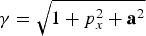 . Assume the two pulses have the same frequency ω2 = ω1 = ω0, the pump pulse is right-circularly-polarized, a1 = a 10[êy cos(2πξ) + êz sin(2πξ)], and the injection pulse is either right or left-circularly-polarized, a2 = a 20[êycos(2πξ + 4πτ) ± êzsin(2πξ + 4πτ)] by taking the upper or lower sign, where a 20≪a 10. Then Eq. (3) is rewritten by

taking  . Since both ξ and p x are functions of τ, usually Eq. 4 is not easily evaluated. For convenience, one can separate the integral in Eq. (4) into the sum of many integrals within a laser period and analyze the characteristic of the integral in a laser period. Note that under the circularly-polarized pump pulse, the relativistic factor γ varies slowly within a laser period (consider the pulse duration is much larger than T 0). This still holds under the assumption of small perturbations. Therefore, within a laser period, the integral of Eq. (4) is approximately given by

When taking the upper sign in the integrand of term (5) for the two pulses having the same polarization, it reduces to sin(4πτ), which is a periodic function of τ. Then the integral (5) is equal to zero. Because this is an integral value within an arbitrary laser period, Eq. (4) vanishes, i.e., ΔH (0) = 0. This indicates that the perturbation generated by the injection pulse at the same polarization with the pump pulse does not lead to effective electron injection.
The lower sign in the integrand of term (5) denotes the opposite polarization of the injection pulse with the pump pulse. In this case, the integrand reduces to sin(4πξ + 4πτ), and the integral part of term (5) becomes ∫ττ+1 sin(4πξ + 4πτ)dτ. Only when an electron is in-phase with the pump pulse or ξ is constant, the integral is zero always. However, generally ξ varies with τ, which destructs the periodic property, so that the integral has chance to be positive or negative. Thus, after being perturbed, there may be some electrons with sufficient ΔH (0) < 0 for being injected and trapped in the wakefield. This suggests that the perturbation generated by the injection pulse at the opposite polarization with the pump pulse can be effective.
The above results can be understood as follows. The perturbation contributed by the y-direction component of the total vector potential is given by ∫ττ+1∂/∂τ [cos(2πξ)cos(2πξ + 4πτ)]dτ = −2π∫ττ+1 sin(4πξ + 4πτ)dτ. That contributed by the z-direction component is ±∫ττ+1∂/∂τ[sin(2πξ)sin(2πξ + 4πτ)]dτ = ±2π∫ττ+1 sin(4πξ + 4πτ)dτ. When the rotating directions of the electric fields of the two pulses are opposite (under the same polarization), the perturbations generated by the y-direction and z-direction components are anti-phased and consequently cancel each other. While the rotating directions of the two pulses are the same, the perturbations produced by the y-direction and z-direction components are in-phase and thereby reinforce each other.
One-dimensional PIC simulations are invoked to check the results presented above. We take an uniform plasma slab with an unperturbed electron density of 0.002n cr, where n cr = mω02 /4πe 2 is the critical density. The pump pulse is fixed with the right-circular-polarization. It has the amplitude a 10 = 1.5 and the width of 20T 0, and propagates along the +x-direction. The injection pulse, either right or left circularly-polarized, has the amplitude a 20 = 0.02, 0.2, and the width of 20T 0, and propagates along the −x-direction. The two pulses with the same frequency (unless stated otherwise) and rectangular profiles, start to overlap at (x,t) = (95λ0, 955T 0), and separate at (x,t) = (95λ0, 975T 0). Without the injection pulse, no electron is injected into the first accelerating bucket of the wakefield at the given conditions.
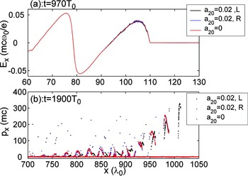
Figure 1a shows the spatial distributions of laser wakefields during the overlapping period of the two pulses. One can see that the injection pulse either right or left circularly-polarized with a 20 = 0.02 affects the wakefield of the pump pulse quite slightly. The approximation used previously in our Hamiltonian approach applies here. In Figure 1b, one observes that the injection pulse with the left circular-polarization helps to inject electrons into the first acceleration bucket of the wakefield. Whereas, with the injection pulse right-circularly-polarized, no electron is injected into the first bucket, and the electron phase space distribution nearly coincides with that without the injection pulse. These simulation results accord with the above analysis.
(a) The spatial distributions of laser wakefields, where three lines with different colors denote the injection pulse with the left(L) circular-polarization (black) and the right(R) circular-polarization (blue), and no injection pulse (red), respectively; (b) The corresponding phase space distributions of electrons at t = 1900T 0.

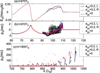
Further simulations with higher amplitudes of the injection pulse suggest that our analysis given above holds when a 20 < 0.05. However, when a 20 ≥ 0.05, the injection pulse with the right circular-polarization can also create electron injection into the first bucket. In this case, the impact of the injection pulse on the wakefield becomes appreciable, and the small perturbation approximation is not valid. Either right circularly-polarized or left circularly-polarized injection pulse can break the conservation of the Hamiltonian system through perturbing the wakefield, and consequently Hamiltonians of some background electrons are possible to be decreased (or some electrons can be preaccelerated). And for the two pulses with opposite polarizations, the perturbations produced, respectively, by the y-direction and z-direction field components should be more coherent than those for the two pulses with same polarization. As a result, the wakefield perturbation for the two pulses with opposite polarizations can be larger and the electron injection can be more efficient, which can be seen in simulations. Figure 2 (with a 20 = 0.2) shows that the injection pulse with the left circular-polarization injects more electrons into the first bucket (see Fig. 2c), introduces larger perturbations of electron motion (see Fig. 2b), and causes stronger destruction on the wakefield (see Fig. 2a) than the right circular-polarized injection pulse. Besides, in the case of left circular-polarized injection pulse, the “beam-loading” effect (Esarey et al., Reference Esarey, Hubbard, Leemans, Ting and Sprangle1997) leads to that the average energy (43 MeV) of trapped electrons in the second bucket is much smaller than that (105 MeV) in the first bucket. The first electron bunch can be picked out using a magnetic field (Umstadter et al., Reference Umstadter, Kim and Dodd1996). And energy spread of the first electron bunch is 0.7%.
(a) The spatial distributions of laser wakefields, where three lines with different colors denote the injection pulse with the left(L) circular-polarization (black) and the right(R) circular-polarization (blue), and no injection pulse (red), respectively; (b) The corresponding phase space distributions of electrons at t = 970T 0; (c) The corresponding phase space distributions of electrons at t = 1900T 0.

3. IMPACT OF THE INJECTION PULSE FREQUENCY
In the following, we shall discuss the impact of the frequency of the injection pulse on electron injection. The form of the pump pulse is not changed and the injection pulse takes the form 
 . Then Eq. (4) is rewritten by

Then the integral of the integrand in Eq. (6) within an arbitrary laser period is approximately given by


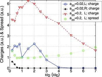
Terms (7) and (8) denote the cases of the two pulses with different polarizations and the same polarization, respectively. Term (7) can be estimated in a similar way to that of term (5), i.e., electron injection should also be created even if ω2 ≠ 1. The corresponding PIC simulations are shown by the blue solid line in Figure 3 and one can see that the injection pulse with 0.5 ≤ ω2 ≤ 3 creates electron injection efficiently. Qualitatively, the injection electron number first increases with ω2, then decreases with it. First, the coefficient ahead of the integral in Eq. (7) is proportional to ω2. Meanwhile, since the integrand varies with τ faster for a larger ω2, it can experience more periods within a pump pulse period. Then ΔH (0), obtained by the sum of more random numbers (positive or negative), inclines to be zero. The competition of the two cases may account for the phenomenon, the number of injected electrons first increases and then decreases with the increasing ω2 as shown in Figure 3. Increasing a 20 from 0.02 to 0.2, the charges and energy spread of trapped electron beams are shown by the red broken line and the green dotted line in Figure 3. One sees that the injection pulse with 0.5 ≤ ω2 ≤ 3 can produce electron injection efficiently and the corresponding energy spread changes slightly.
The injected electron beam charge and energy spread as a function of the injection pulse frequency.

One can use term (8) to discuss the case of the same polarization. When ω2 ~ 1, the result should be similar to the case of ω2 = 1, i.e., almost no electrons are injected. When ω2 deviates from 1, the varying trend of the injected electron number with ω2 should be similar to the case of different polarizations. One can see the black dash-dotted line accords with the above analysis.
4. SUMMARY
In conclusion, we have discussed the dependence of electron injection on the polarization and the frequency of the circularly-polarized injection pulse. The injection pulse with the opposite polarization from the pump pulse can generate electron injection more efficiently than the one with the same polarization as the pump pulse. The injection pulse with the frequency different from the pump pulse (e.g., ω2/2 ≤ ω2 ≤ 3ω0) can create electron injection efficiently, too, provided it has the opposite polarization with the pump pulse.
ACKNOWLEDGMENTS
This work was supported in part by the National Natural Science Foundation of China (Grant Nos. 10425416, 10674175, 60621063), the National High-Tech ICF Committee in China, and the National Basic Research Program of China (Grant No. 2007CB815105).