Introduction
Modern communication systems such as GPS, RFID, WLAN, WiMAX, etc. require circularly polarized (CP) antennas. CP antennas have better immunity toward multipath fading and polarization mismatch as compared with linearly polarized (LP) antennas [Reference Chang, Wong and Chiou1]. In CP radiations, two orthogonal modes with equal amplitude which are 90° out of phase are excited. CP antennas can be broadly classified into two types: single fed or dual fed antennas. For the dual fed CP antennas, a 90° hybrid is required to have the essential phase shift of 90°. Dual fed antennas have complex designs, larger size, and higher losses [Reference Garg, Bhartia, Bahl and Ittipiboon2]. Thus, single fed CP antennas are more preferred over the dual fed antennas. Several single fed CP antennas have been reported in the literature. The two orthogonal modes with equal amplitude with 90° phase difference can be achieved by introducing an asymmetry and/or perturbations in different monopoles [Reference Sharma and Gupta3–Reference Ding, Guo and Gao8] and slot antennas [Reference Jan, Pan, Chiu and Chen9–Reference Nosrati and Tavassolian11] in single fed antennas. A single microstrip fed CP square patch antenna with a pair of truncated corners analyzed and designed using a multiport network model is presented in [Reference Sharma and Gupta3]. In [Reference Wong and Wu4], CP radiations are obtained by cutting slits of a square patch. A microstrip fed CP antenna with a cross-shaped slot is presented in [Reference Iwasaki5]. All the above reported works have mostly narrow 3 dB-axial ratio bandwidths (ARBW).
With the advancement of communication technology, CP antennas with a wide impedance bandwidth and wide ARBW are in great demand [Reference Augustin and Denidni6–Reference Nosrati and Tavassolian11]. In [Reference Augustin and Denidni6], a trapezoidal structure is presented which possess both the CP (ARBW = 8%) and LP radiations. In [Reference Jan, Pan, Chiu and Chen9], a broadband coplanar waveguide fed CP slot antenna with an open slot having an ARBW of 27% is presented. However, their larger size and complex design restrict its application in portable wireless devices. Two orthogonal degenerate modes in [Reference Ellis, Zhao, Wu, Ding, Nie and Liu10] are generated by protruding the square shaped slot with a metallic stub and the asymmetric microstrip feed line with 40% ARBW. An ARBW of 44.9% is achieved in coplanar waveguide (CPW) fed planar monopole antenna by adding a vertical stub and cutting a horizontal slit on the ground plane [Reference Zhang, Jiao, Ding, Chen and Weng7]. However, designing a compact CP monopole antenna with the wide impedance bandwidth as well as wide ARBW is a true challenge for antenna designers.
A self-complementary antenna was initially reported in [Reference Mushiake12] along with its frequency-independent broadband characteristics. Self-complementary concepts were applied over a monopole or a slot for size miniaturization in [Reference Pu, Fujimoto and Shiming13]. Later, the quasi-self-complementary (QSC) structures are employed to obtain wide or multi-band impedance characteristics [Reference Guo, Wang, Chen and Parini14–Reference Lin, Huang and Chen16] in compact dimensions. Here, the QSC structure is employed to obtain a wide impedance bandwidth along with wide 3 dB ARBW characteristics.
In this paper, a compact CP modified QSC antenna with a wide 3 dB ARBW is presented. The wideband circular polarization of the proposed antenna is achieved by asymmetrical QSC structure and the stepped stub attached to its extended ground plane. In the present design, a 3 dB ARBW of 1.6 GHz is obtained which is nearly 50% (relative to the center frequency of 3.2 GHz). The proposed antenna is suitable for several wireless communication systems such as 2.4 GHz WLAN (2400–2484 MHz), WiMAX (2500–2690 MHz, 3200–3800 MHz) bands, etc.
Antenna configuration
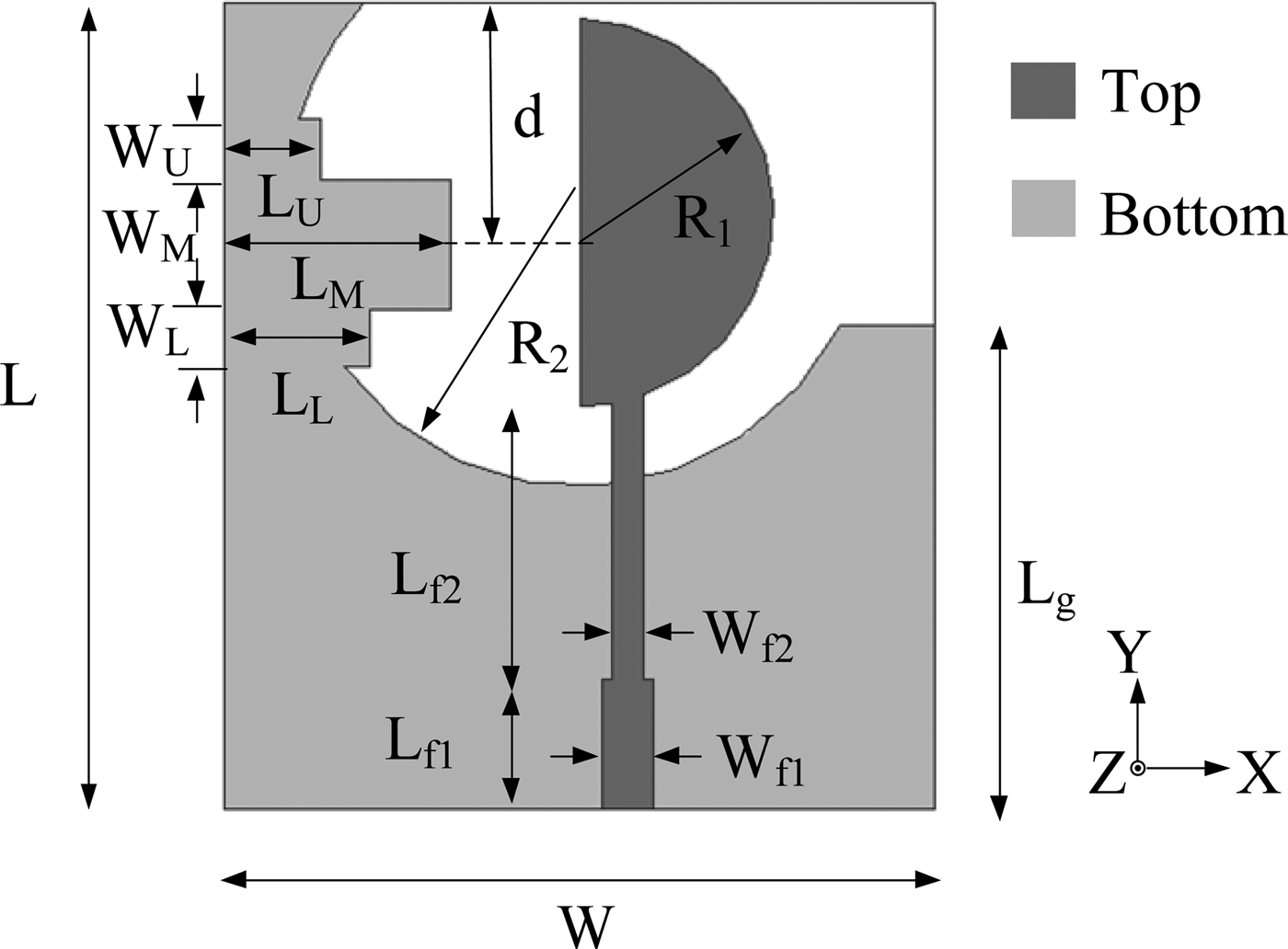
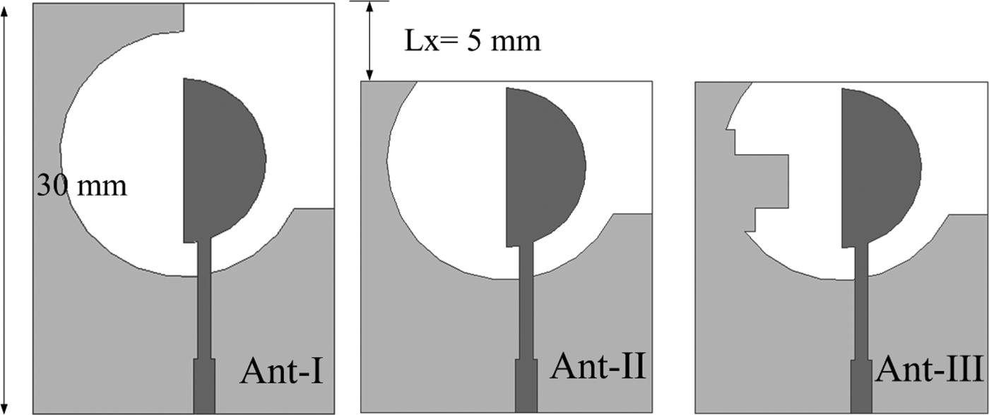
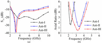
The geometry of the proposed CP antenna is shown in Fig. 1. It is fed by a 50 Ω microstrip feed line printed on the top of the substrate. A low cost FR4 substrate having a dielectric constant of 4.4, loss tangent of 0.02, and thickness of 0.8 mm is used in the present design. The overall size of the proposed antenna is 25 mm × 22 mm. The proposed antenna is the modified QSC structure, which consists of a semi-circular patch of radius R 1 and a modified complementary etched ground plane of radius R 2 with a stepped stub attached to its extended ground plane as shown in Fig. 1. Figure 2 shows the evolution of the proposed structure from the basic QSC structure to the final wideband CP antenna. The S 11 parameters and the axial ratio of the different antennas shown in Fig. 2 are plotted in Fig. 3.
Geometry of the proposed CP antenna.

Evolution of the proposed antenna: (a) Ant-I, (b) Ant-II, and (c) Ant-III.

Simulated (a) S 11 parameters and (b) axial ratio for Ant-I, Ant-II, and Ant-III.

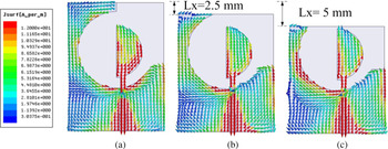
It is well-known that a QSC structure based antenna exhibits the wide impedance bandwidth. The basic QSC structure (Ant-I) resonates at two frequencies: 3.5 and 7.2 GHz. Ant-I has an asymmetrical ground plane that results in narrow band CP radiations (3-dB ARBW = 2.1–2.5 GHz, 17.4%) [Reference Jan, Pan, Chiu and Chen9]. At the first resonant frequency, 3.5 GHz, Ant-I mainly have vertically polarized radiations. It is due to the presence of oppositely oriented horizontal currents in the ground plane which cancels each other and results in vertically polarized radiations [Fig. 4(a)].
Surface current distribution for different values of L x at 3.5 GHz: (a) L x = 0 mm, (b) L x = 2.5 mm, and (c) L x = 5 mm.

In order to obtain CP radiations, the extended ground plane along with the substrate of the basic QSC structure is shortened by L x [Fig. 2(b)]. The surface current distributions at 3.5 GHz for L x = 2.5 mm and L x = 5 mm are plotted in Fig. 4(b) and (c), respectively. As the value of L x increases, the resultant horizontal currents are generated in the ground plane. For L x = 5 mm (Ant-II), a significant amount of horizontal currents is produced which along with vertical currents results in CP radiations. Thus, the shortening of the ground plane not only reduces the size of the antenna, but also results in CP radiations.
The impedance bandwidth of Ant-II is from 2.3–7.6 GHz, while the 3-dB ARBW is 2.9–3.8 GHz, which is nearly 26.9%. Furthermore, to enhance ARBW, a stepped stub is introduced in the extended ground plane (Ant-III). This stepped stub creates an equal horizontal current in-phase quadrature with the vertical currents, that results in a wideband 3-dB ARBW (2.4–4.0 GHz, 50%).
Circular polarization mechanism
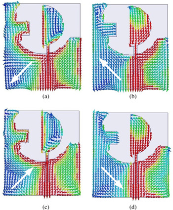
In order to understand the operating principle of the proposed antenna, the time varying surface currents of the proposed antenna at 3.5 GHz are plotted in Fig. 5. As reported in literature [Reference Jan, Pan, Chiu and Chen9], the asymmetry in the ground plane as well as asymmetry in the feed line will result in wideband CP operation. It can be observed that the surface currents rotating in the clockwise direction results left-hand CP (LHCP) radiation in the +z-direction and right-hand CP (RHCP) radiation in the −z-direction.
Simulated surface current distribution of the proposed antenna at 3.5 GHz for (a) ωt = 0°, (b) ωt = 90°, (c) ωt = 180°, and (d) ωt = 270°.

Parametric analysis
In order to understand the basic underlying principle of the proposed CP antenna, the parametric study of different geometrical parameters is conducted for a wide impedance bandwidth and wide 3 dB ARBW. The effects of different geometrical parameters are discussed as follows to obtain the final dimensions of the proposed antenna.
Effect of ground plane parameter, L g
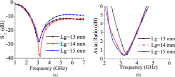
The variations in parameter L g of the ground plane greatly influence antenna's |S 11| characteristics and AR as shown in Fig. 6. The increase in the value of L g affects the impedance matching at the upper frequency edge, while the resonant frequency at the lower frequency remains almost unaltered. Whereas, the ARBW improves at the lower frequency edge as L g increases. Hence, by considering the trade-off between the impedance bandwidth and ARBW, L g = 14 mm is chosen as an optimal design parameter.
Simulated (a) S 11 parameters and (b) axial ratio for different values of L g.

Effect of radius of semi-circular feed structure, R 1
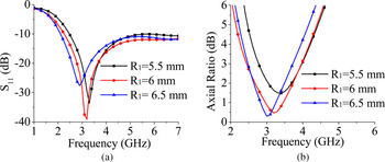
The radius R 1 of the semi-circular feed structure also affects the antenna's |S 11| and AR as shown in Fig. 7. It can be observed that an increase in the value of R 1, shifts the lower frequency edge of S 11 curve toward the lower value. The value of R 1 = 6 mm provides the wide ARBW, hence it is chosen as an optimal design parameter.
Simulated (a) S 11 parameters and (b) axial ratio for different values of R 1.

Effect of introduction of a stepped stub
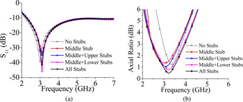
The effects of the stepped stub on the S 11 parameter and axial ratio performance are presented in Fig. 8. The stepped stub can be divided into three smaller stubs: upper stub, middle stub, and lower stub. First, the middle stub is introduced at the central position of the extended ground plane. Subsequently, the upper and lower stubs are added separately to evaluate their effects on antenna's performance. Finally, all the three stubs are applied together to obtain our designed antenna. It can be observed from Fig. 8(a) that with the introduction of stubs S 11 curve shifts toward the right with a slight change in the impedance bandwidth. While the introduction of stubs has a significant effect on the axial ratio performance of the antenna. The 3 dB ARBW is maximum (1.6 GHz) for the combination of all the three stubs, i.e. stepped stub.
Simulated (a) S 11 parameters and (b) axial ratio for combination of different stubs.

Effect of length of middle stub, L M
The variation of the length L M of middle stub on the S-parameters and axial ratio performance is plotted in Fig. 9. It can be observed that as the value of L M increases, S 11 curve shifts toward the left. The ARBW is maximum when the value of L M equals 6 mm. Hence, L M = 6 mm is an optimum choice for the proposed design.
Simulated (a) S 11 parameters and (b) axial ratio for different values of L M.

Effect on the position of stepped stub, d
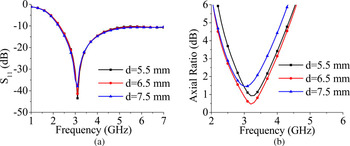
The position of the stepped stub ‘d’ is optimized in this section. As can be seen from Fig. 10(a), there is insignificant effect on S 11 characteristics of the proposed antenna. It can be observed from Fig. 10(b) that the ARBW is maximum for the value of d = 6.5 mm. Thus, d = 6.5 mm is chosen as an optimal design parameter for the position of the stepped stub.
Simulated (a) S 11 parameters and (b) axial ratio for different values of d.

The optimized parameters of the proposed antenna are: L = 25 mm, W = 22 mm, L f1 = 4 mm, L f2 = 8.6 mm, W f1 = 1.6 mm, W f2 = 1 mm, L g = 14 mm, R 1 = 6 mm, R 2 = 9 mm, W U = 1.9 mm, L U = 3 mm, W M = 4 mm, L M = 7 mm, W L = 1.8 mm, L L = 4.5 mm, and d = 6.5 mm.
Results and discussions
In order to verify the present design approach, the proposed antenna with the optimized design parameters is fabricated and its radiation characteristics are measured. The simulated and measured results are shown in Fig. 11 and there is a good agreement between them. The measured impedance bandwidth is 4.36 GHz (2.43–6.79 GHz, 95%). The standard laboratory procedure described in [Reference Toh, Cahill and Fusco17] has been adapted for axial ratio measurements. The simulated and measured axial ratio performances in the broadside direction are shown in Fig. 11(b). The measured ARBW is 1.5 GHz (2.4–3.9 GHz, 48%).
Simulated and measured (a) S 11 parameter and (b) axial ratio.

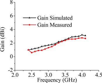
The measured far field radiation patterns of the proposed antenna in the xz- and yz-planes at 2.8 and 3.5 GHz are shown in Fig. 12. It is clear from the figure that the antenna exhibits a bidirectional radiation with opposite circular polarizations. The antenna has LHCP radiations for z > 0, which provides maximum radiations nearly in the broadside direction. While it has RHCP radiations for z < 0, which provides the maximum radiations approximately at ϕ = 0° and θ = 180°. The peak gain of the proposed antenna is plotted in Fig. 13. The antenna has the peak gain of 3 dBi with a variation of 1–2 dB within the 3 dB ARBW. The antenna gain is low at the lower frequencies, due to its smaller dimensions, which indicates the tradeoff between the gain bandwidth and its dimensions. In the middle and higher frequencies, the gain varies between 2 and 3 dBi.
Measured radiation patterns of the proposed antenna at (a) 2.8 GHz and (b) 3.5 GHz.

Simulated and measured gain of the proposed antenna.

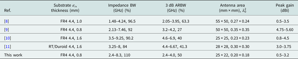
Table 1 lists a comparison of the proposed antenna with the other similar antennas reported in the literature. It can be observed from the table that the proposed antenna has comparable or better performance over the other antennas in terms of either size or ARBW.
A comparison of the proposed CP antenna with other CP antennas

Conclusion
A compact wideband CP antenna using a modified QSC structure is designed, fabricated, and its characteristics are measured. The proposed antenna has a wide impedance bandwidth (110%) and wide ARBW (50%). The asymmetrical modified QSC structure and the stepped stub attached in its extended ground plane result in wideband CP radiations. The measured results show that the presented CP antenna will be a potential candidate for WLAN bands (2400–2484 MHz) and WiMAX bands (2500 MHz–2690 MHz, 3200–3800 MHz).
 Gunjan Srivastava received her Ph.D. degree from the Indian Institute of Technology (Indian School of Mines), Dhanbad, India in Microwave Engineering in 2016. At present, she is working as Women Scientist in the Department of E&ECE at the Indian Institute of Technology (IIT Kharagpur). She has authored or co-authored over 10 peer-reviewed international journal and conference papers. Her main research interests are design of ultra-wideband, reconfigurable, and MIMO antennas.