Introduction
The fifth generation of mobile system requires high gain ultra wide-band (UWB) antennas to fulfill mobile and modern wireless communication needs. Ultra-wideband antenna is one of the most important components and has attracted significant research power in recent years due to the various advantages such as low power consumption, low complexity, and high bandwidth for modern wireless communication applications [Reference Mobashsher and Abbosh1, 2]. Ultra-wideband is an emerging new technology for broadband internet access and public safety applications and the Federal Communications Commission allotted the spectrum in the region from 3.1 to 10.6 GHz for UWB systems issued in February 2002 [Reference Kushwaha and Kumar3]. In order to fulfill the challenging requirements of modern wireless communication systems and to obtain improved bandwidth of a UWB antenna, several techniques have been reported in the literature. In [Reference Soliman, Dwairi and Alahmadi4–Reference Paul, Kandasamy and Sharawi7], various slot configurations with proper dimensions have been etched into the ground to modify the reference antennas bandwidth. The bandwidth can also be increased by exciting two types of resonant modes, namely the slot and monopole modes as reported in [Reference Guo, Tian, Wang, Luo and Ji8, Reference Anum, Singh, Mishra and Tripathi9]. The peak gain of the UWB antenna is low due to its high back lobe radiation, further in order to improve the directionality by minimizing back lobe radiation a frequency selective surface (FSS) reflector was employed below the UWB antenna [Reference Kushwaha and Kumar10–Reference Yuan, Xi and Zhao12]. The modeling of a polarization insensitive UWB FSS with band stop response is reported in [Reference Abdulkareem and Gopalakrishnan13].
In this paper, a monopole UWB patch antenna with an FSS reflector is designed and proposed for the enhancement of the gain and bandwidth. Initially, the reference antenna is a monopole type with a square radiator and fed by a microstrip feed line with a partial ground plane. Further, a slot is introduced on the patch and in the ground plane along with blending and chaffering operation to modify the reference antenna bandwidth characteristics and to improve its radiation performance throughout the frequency range. Finally, to achieve the high gain for broadband applications, one layer FSS reflector is proposed to exhibit the desired reflection in the entire UWB band. The proposed antenna is designed and investigated using the CST-EM software package in terms of the antennas different parameters including impedance bandwidth characteristics, radiation patterns, antenna's gain, radiation efficiency, and group delay evaluation.
UWB antenna design
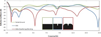
The proposed monopole UWB microstrip patch antenna is shown in Fig. 1. The antenna is designed on Rogers RO4003C substrate having a relative permittivity of 3.55 and loss tangent 0.0027. The overall dimensions of the substrate are Ws × Ls mm2 and the height is 1.52 mm. The dimensions of radiating patch element are (in mm): patch width (WP) = 20 mm, patch length (LP) = 23 mm, feed length (Lf) = 24 mm and to offer the perfect impedance matching of 50 Ω the feed width (Wf) of 3.5 mm has been chosen. Initially, on the bottom side of the substrate, there is a partial ground plane of Wg × Lg mm2, resulting in an impedance bandwidth of 71% (1.9–4 GHz). Further to achieve the wide impedance bandwidth a rectangular slot is etched on the ground plane, which has dimensions of Ldgs × Wdgs mm2 and achieved impedance bandwidth of 114% (1.9–7 GHz). To further increase the impedance bandwidth, a chamfering technique has been applied on the edges of a rectangular slot at the ground side. Finally, an impedance bandwidth of 157% (1.8–15.2 GHz) is achieved. Due to the effect of E field excitation on DGS, it will make a direct influence on the current distribution and radiation patterns are slightly deteriorating at the higher frequencies [Reference Saraswat and Kumar14].
UWB antenna with the modified ground.

To obtain the stable radiation patterns at higher frequencies, two identical vertical slots of the LS1 × WS1 mm2 size are etched out from the patch and also blending operation has been applied on the corner edges of the patch as well as a ground plane. The position and size of the slots have been chosen according to the distribution of current and electric field at the operating frequencies [Reference Ibtisam and Otman15]. The optimized design parameters of the proposed UWB antenna have been depicted in Table 1.
Parameters of proposed UWB antenna

The simulation result of this reference antenna is shown in Fig. 2. It is observed that a good impedance matching has been achieved over the operating frequency band from 1.8 to 15.2 GHz.
Simulated return losses of an antenna with respect to ground modification.

Further, in order to compare the proposed work with the available literature, the proposed UWB antenna has been compared in terms of bandwidth enhancement and peak gain with the few available broadband-based antennas in the literature as shown in Table 2.
Comparative analysis of the proposed UWB antenna with few broadband-based research works

The proposed antenna covers a wide impedance bandwidth of 157% from 1.8 to 15.2 GHz with − 10 dB return loss however the peak gain of an antenna is 6.4 dBi. The gain of the antenna with respect to the entire operating band is as shown in Fig. 3.
UWB antenna Gain vs. Frequency plot without FSS.

Fundamentally UWB antennas lead to very high interference because of its omnidirectional radiation characteristics. In order to create unidirectional radiation characteristics, a cavity-based resonator can be used, which redirects the back radiation and enhance the gain of the antenna. The advances in periodic structures have led to the development of FSS reflectors, which enhance the gain over the UWB range owing to their in-phase reflection [Reference Swetha and Naidu20]. In this work, to enhance the gain of the proposed antenna a novel FSS reflector has been proposed with the UWB antenna. The proposed UWB antenna with an FSS reflector enhances the antenna bandwidth, peak gain and directivity.
FSS design and analysis
The geometry of the proposed FSS unit cell is shown in Fig. 4 and the optimized design parameters of the proposed FSS unit cell have been depicted in Table 3. The FSS structure comprises a single metallic square loop, an annular ring and four dipole elements, printed on the FR-4 (lossy) dielectric substrate of 23 mm × 23 mm × 1.6 mm size having dielectric permittivity (ɛr) = 2.2 and loss tangent (δ) is 0.025.
Configuration and geometrical parameters of proposed FSS.

Parameters of proposed FSS

Initially, merely the metallic square loop has been designed and simulated, which provided the narrow bandwidth (1.6–4.8 GHz) having an outer dimension of 22.5 mm × 22.5 mm and the inner dimension is 14 mm × 14 mm. Further with the aim to achieve a wider bandwidth in the UWB range, the unit cell FSS geometry has been modified by adding an annular ring with the outer and inner radius of 7.5 and 6 mm respectively and four dipole elements of 14 × 1 mm2 have been added inside a square loop. After modifying the structure, the operating frequency is shifted in right and the transmission characteristic bandwidth is improved in the frequency range of 2.1–12.6 GHz. The comparison in transmission characteristics of square loop FSS and the proposed FSS is shown in Fig. 5. It can be observed that the proposed FSS is covering the complete UWB range.
Transmission characteristics of square loop FSS and proposed FSS.

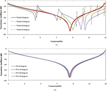
The proposed UWB FSS is analyzed for the various incident angles of a plane wave. The incident angles of a plane wave in terms of θ (theta) and Ø (phi) varies from 00 to 450. Figures 6(a) and 6(b) represents the transmission characteristics of the proposed UWB FSS for incident angles optimized from 00 to 450.
Transmission characteristics of proposed UWB FSS for various incident angles optimized (a) Theta (θ) (b) Phi (Ø).

The analysis of reflection phase response for both TE and TM modes varies linearly from −1800 to 1800, within the complete UWB range of 1.33 to 13 GHz is depicted in Fig. 7. From the figure, it can be seen that the reflection phase decreases with a frequency which is an essential requirement for the FSS to enhance the gain when used as a superstrate [Reference Saraswat and Kumar14].
Reflection phase of the proposed FSS for TE and TM modes.

Equivalent circuit model of FSS
The geometry of the complete unit cell element and its equivalent circuit are shown in (Figs 8(a) and 8(b)) respectively. The equivalent circuit (EC) model provides a fast solution and required very less computational resources.
Equivalent circuit model complete FSS Unit cell structure.

As mentioned above, the complete unit cell FSS structure comprises a single metallic square loop, an annular ring and four dipole elements. So, the equivalent circuit model of the complete unit cell FSS, has been obtained by combining the individual equivalent circuit model of a single metallic square loop, an annular ring and four dipole elements. The individual equivalent circuit models with its equivalent inductive reactance's and capacitive susceptance's of a single metallic square loop, an annular ring and four dipole elements are shown as below.
The theory of transmission line supports in the development of an equivalent circuit model of FSS using inductive (L) and capacitive (C) lumped components. An equivalent circuit of FSS representing an infinite array of conducting strips, developed by Marcuvitz [Reference Marcuitz21] allows the computation of inductive (L) and capacitive (C) values. The square loop array and its equivalent circuit model is shown in (Figs 9(a) and 9(b)) respectively. The square loop FSS represents the vertical and horizontal metal strips, the vertical metal strip acts as an inductive reactance and horizontal strips as a capacitive reactance.
(a) Square loop cell structure (b) Equivalent Circuit Model.

The values of L and C can be calculated by equation (1) and (2) as presented in [Reference Sheng, Gao and Liu22, Reference David, Rafael, Caldeirinha and Fernandes23]. The equivalent inductive reactance and capacitive susceptance are given as follow. The inductive reactance and capacitive susceptance depend upon the, periodicity p, length d, width s, and effective permittivity of material and gap g between the adjacent strips of the square loop FSS.


Similarly, the circular loop array and its equivalent circuit model are shown in (Figs 10(a) and 10(b)) respectively. Accordingly, the values of lumped parameters L and C can be obtained for a circular loop FSS using equation (3) and (4) as presented in [Reference Ali Ramezani, Zaker Hossein and Abolghasem Zeidaabadi24]. The value of inductance and capacitance is determined by loop width w, cell size p and length d, effective permittivity of the material and the average gap between an adjacent loop ga. Therefore, inductive reactance (X L) and capacitive susceptance (B C) can be given as follows.


(a) Circular loop cell structure (b) Equivalent Circuit Model.

Here, in equation (3) and (4) the factor π/4 and π/2 are owing to the circular loop (πd) compared with the square loop factor (4d) and the length of the half-circular loop πd/2 compared with square loop length d. Here ga is the average gap between two adjacent circular loop and can be calculated as [Reference Sheng, Gao and Liu22].

Likewise, the cross dipole array and its equivalent circuit model is shown in (Figs 11(a) and 11(b)) respectively and for cross dipole, the normalized reactance and susceptance can be given as follows. Z 0 is the free space impedance, B g is the susceptance due to the gap capacitor of two adjacent cells, B d is the susceptance due to the (p–d) spaced capacitor, d is the length, w is the width and p is the periodicity. The total susceptance Bc = B g + B d [Reference Udeshwari, Narang, Singh and Yadav25].


(a) Cross dipole array structure (b) Equivalent Circuit Model.

Equivalent circuit model of FSS
Square loop FSS
Figures 12(a), 12(b) and 12(c) show the square loop FSS, the equivalent circuit of square loop FSS and comparison of S-parameter between square loop FSS and its equivalent circuit respectively. The design of an equivalent circuit is carried out in CST schematic circuit design environment with the optimized value of LC pairs is L = 0.4 nH and C = 7 pF. Figure 11(c) shows a very close agreement between simulated results of square loop FSS with its equivalent circuit model.
(a) Square Loop FSS (b), Equivalent circuit of square loop FSS, (c) S-parameter comparison between square loop FSS and its equivalent circuit.

UWB FSS
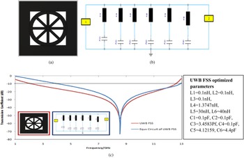
Figures 13(a), 13(b) and 13(c) show the UWB FSS, the equivalent circuit of UWB FSS and a comparison of S-parameter between UWB FSS and its equivalent circuit respectively. The design of the equivalent circuit is carried out in CST schematic circuit design environment with the optimized value of six LC pairs are L1 = 0.1 nH, L2 = 0.1 nH, L3 = 0.1 nH, L4 = 1.3747 nH, L5 = 30 nH, L6 = 40 nH and C1 = 0.1 pF, C2 = 0.1 pF, C3 = 3.4583 Pf, C4 = 0.1 pF, C5 = 4.12159, C6 = 4.4 pF.
(a) UWB FSS, (b) Equivalent circuit of UWB FSS, (c) S-parameter comparison between UWB FSS and its equivalent circuit.

Figure 13(c) shows a very close agreement between the simulated results of square loop FSS with its equivalent circuit model.
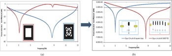
Figure 14(a) and 14(b) depicted the comparison of transmission characteristics in 3D EM environment and in 2D schematic circuit environment of CST for both square loop FSS as well as UWB FSS structure and their equivalent circuit respectively.
S-parameter comparison between (a) UWB FSS and Square loop FSS, (b) Equivalent circuit of UWB and square loop FSS.

Antenna with FSS reflector for gain enhancement
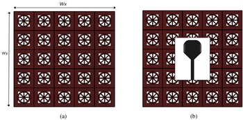
The array of proposed FSS is shown in Fig. 15(a) and the array of FSS incorporated with the proposed antenna is shown in Fig. 15(b). To enhance the gain of the proposed UWB antenna the FSS is implemented behind the antenna and has been used as a reflector. When the radiated waves impinge on the FSS reflector, it will reflect back and in turn affects the antenna characteristics. The wave radiated by the antenna and wave reflected from the FSS are in phase to enhance the antenna gain. Therefore, the phase of the antenna radiated wave and FSS reflected wave must satisfy the following condition [Reference Kushwaha and Kumar11,Reference Rabia and Makoto26].

(a) The array of FSS (b) FSS array with the proposed antenna.

In equation (9), φFSS is the reflection phase of FSS, β is the propagation constant of free space given by 2π/λ and h is a height at which FSS is placed behind the antenna. From the above equation, by considering the reflection phase φFSS is zero then the optimal height “h” can be taken as half of the wavelength $\left({{\lambda \over 2}} \right)$ . From Fig. 6 it has been observed that zero degree phase reflection frequency is found at 8.5 GHz and the optimal height is calculated as 17.6 mm. But to achieve the desired bandwidth and reflection coefficient below −10 dB, the height “h” needs to be optimized and the optimal height “h” between antenna and FSS is found at 36.14 mm. Comparison at H = 17.6 & 36.14 mm is shown in
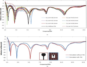
The antenna is placed above FSS at 36.14 mm as shown in Fig. 16. The antenna characteristics are affected due to FSS. Figure 17(a) shows the comparison of the simulated reflection coefficient with FSS for the optimized height (H = 17.16, 28.14, 30.14, 32.14, 34.14, 36.14, 38.14 mm) and without FSS. Figure 17(b) shows the proposed height (H = 36.14 mm) between the antenna and FSS. It can be observed that the impedance bandwidth is intact even after the application of FSS, however, the trivial enhancement in bandwidth and gain is observed at height (H) 36.14 mm. The Comparison table of percentage bandwidth and gain for optimized height is illustrated in Table 4. It can be observed that at the height of 36.14 mm between antenna and FSS providing the excellent bandwidth enhancement of 160% (1.7–15.5 GHz).
UWB antenna based on the FSS reflector.

Reflection coefficient with and without FSS at (a) Optimized height (H), (b) Proposed height (H = 36.14 mm).

Comparative analysis percentage bandwidth and peak gain for the antenna with FSS at optimized height and without FSS.

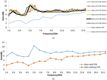
Figure 18 shows the comparison of the simulated gain of UWB antenna with and without FSS at optimized height (H = 17.16, 28.14, 30.14, 32.14, 34.14, 36.14, 38.14 mm). From Table 4, it has been observed that when an antenna is placed at an optimized height h (36.14 mm) with an FSS reflector then the gain of the antenna is significantly increased around 4 to 5 dBi over the complete UWB range. It can be predicted that whenever the wave radiated toward the FSS is reflected back and added to the wave radiated from the antenna and if the two wave components are added in phase then the gain of the antenna improves significantly. The peak gain of 10.4 dBi for the antenna composite is achieved at 5.6 GHz.
Gain of UWB antenna with and without FSS over the complete UWB range at (a) Optimized height (H), (b) Proposed height (H = 36.14 mm).

Further, in order to compare the proposed work with the available literature, the proposed UWB antenna with FSS is compared with few broadband-based antennas with FSS for gain enhancement available in the literature. The comparison is as shown in Table 5.
Comparative analysis of the proposed antenna with FSS over few broadband-based antennas with FSS available in open literature.

Measurement test setup & results discussion
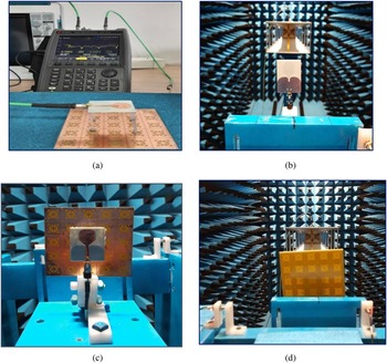
The proposed antenna has been modeled and designed using 3D Electromagnetic Software; CST (Computer Simulation Technology) based on Finite Integration Technique (FIT) and then fabricated. Figure 19 represents the measurement test setup of the fabricated prototype antenna assembled with FSS. The reflection coefficient (S11) is tested using the Keysight Vector Network Analyzer (N9918A) and the radiation patterns have been measured inside an in-house anechoic chamber with an Antenna Measurement Systems.
Measurement setup of proposed antenna with FSS, (a) VNA setup of antenna with FSS, (b) Setup of antenna alone in an anechoic chamber, (c) & (d) Setup of antenna with FSS in an anechoic chamber.

Reflection coefficient (S 11) characteristics
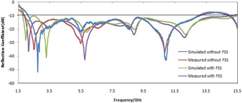
A comparison of the simulated and measured reflection coefficients (S11) of the UWB antenna with and without FSS is shown in Figure 20. It can be observed that, there is close agreement between simulated and measurement results and the impedance bandwidth for antenna without FSS and with FSS are 157% (1.8–15.2 GHz) & 160% (1.7–15.5 GHz) respectively. The slight difference occurred due to the fabrication tolerance and assembly error.
Comparison of simulated and measured reflection coefficients (S11) with and without FSS.

Peak gain
Figure 21 shows the comparison of simulated and measured gain with and without FSS. It can be seen that there is an approx 4–5 dBi improvements in gain for antenna after incorporated with FSS as compared to antenna alone. It can be observed that, there is close agreement between simulated and measured results.
Comparison of simulated and measured gain with and without FSS.

Radiation patterns
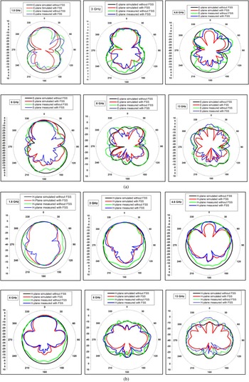
The simulated and measured radiation patterns in E and H plane of the UWB antenna with and without FSS at 1.8, 3, 4.6, 6, 8, and 13 GHz are shown in (Figs 22(a) and 22(b)). It can be seen that the antenna without FSS has almost stable radiation patterns which is nearly omni-directional in H (X–Z)-plane (ϕ = 00) and bidirectional in E (Y–Z)-plane (ϕ = 900) over the entire ultra wideband bandwidth. However, for the antenna with FSS, at higher frequencies, undesirable side lobes are generated with the main lobe due to the multi-direction current distribution and higher-order modes excitation. The simulated and measured radiation patterns are found to be in close agreement. There is a slight difference due to the measurement testing and alignment errors.
Comparison plot of simulated radiation patterns (E-plane and H-plane) of antenna with and without FSS at different frequencies 1.8, 3, 4.6, 6, 8 and 13 GHz (a) E-plane (b) H-plane.

Time response analysis
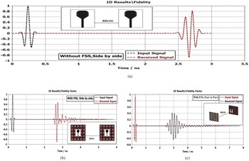
In order to analyze the time domain response, The Fidelity factor plays a vital role to minimize the distortion in the modulated signal. To determine the influence of the designed FSS reflector-loaded UWB antenna on the time-domain performance, two identical antennas were employed as Transmitter (Tx) and Receiver (Rx) devices in side by side and Face to Face configurations. The Fidelity factor is a normalized cross-correlation between the Gaussian source pulse and the received pulse. The correlation (fidelity factor) between transmitted (excited) and received pulse is given by [Reference Sarthak, Pragya and Amit30].

Here, S t (t) is the transmitted or excited signal, S r (t) is the received signal and τ is the time delay between both of the signals. The correlation is done normalization in order to compare the only shape of the signals and not their magnitude as S r (t) is expected to be very lower than S t (t). Antennas are placed at a distance of 66 cm, which is three times of the wavelength of the lowest operating frequency (1.8 GHz).
Figure 22 depicts the time domain analysis for both the configurations of an antenna with and without FSS and it shows the minimum distortion in signal with the fidelity factor of 90% for antenna without FSS as in Fig. 23(a) and 85, 70% for antenna with FSS in side by side and face to face configuration respectively as shown in Figs23(b) and 23(c).
Transmitted and received signal of antenna (a) side by side without FSS. (b) side by side with FSS (c) face to face with FSS.

Group delay
The group delay of an antenna is defined as the negative derivative of phase response with respect to angular frequency (ω). It is an important parameter of UWB communication systems, which measures the signal delay and total phase distortion of the antenna system [Reference Sarthak, Pragya and Amit30,Reference Werner, Grzegorz and Christian31].

Here, ϕ(f) is the frequency-dependent phase response of the radiated signal. Ideally, a non-distorted structure is having constant group delay and linear phase response over the entire frequency band. To have less variation in group delay, the amplitude of antenna transmission coefficient (|S 21|) is usually nearly flat and its phase response shows linearity with respect to frequency.
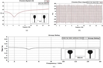
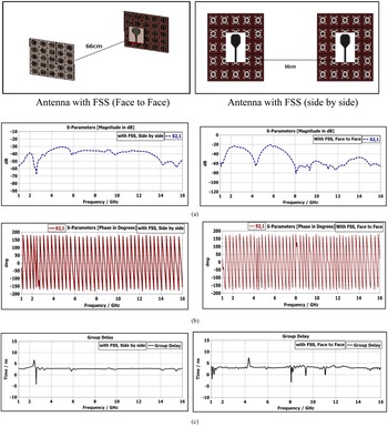
In order to evaluate the same, two identical antennas are positioned with side by side and face to face configuration at 66 cm. Figure 24 shows the magnitude and phase plot of S 21 and group delay of side by side orientation of UWB Antenna without FSS. It has been observed that the magnitude of S21 is remained almost flat and the phase is linear in the entire UWB band with less variation except notch bands.
(a) Transmission coefficient (S21) magnitude in dB (b) S21 phase characteristic (c) group delay in side by side orientation of UWB antenna without FSS.

The magnitude and phase plot of S 21 and group delay of face to face and side by side orientation of the UWB antenna with FSS is shown in Fig. 25. As depicted from the figure of side by side and face to face orientation, the group delay is almost constant with variation less than 1 ns over the entire frequency band without notch bands. Minimal distortion and less variation in the transmitted signal accomplish the requirement of UWB communication systems.
(a) Transmission coefficient (S21) magnitude in dB (b) S21 phase characteristic (c) group delay of antenna for both face to face and side by side configuration.

Conclusion
In this work, a novel UWB antenna, backed by the suspended ground to enhance the impedance bandwidth and a novel FSS reflector to enhance the gain of UWB antenna is presented. At first, a novel UWB antenna with modified ground and patch is proposed, which covers a wide impedance bandwidth of 157% from 1.8 to 15.2 GHz with a peak gain of 6.4 dBi. Further, in order to enhance the gain of the antenna, the novel FSS reflector which consists of 5 × 5 arrays with the dimension 115 × 115 × 1.6 mm3, located below the proposed UWB antenna. The proposed FSS enhanced the peak gain of an antenna from 6.4 to 10.2 dBi and it also gives ultra-wide stopband response over the entire range with single dielectric layer. The proposed antenna almost presents stable radiation patterns which is nearly Omni-directional in H-plane over the entire ultra wideband bandwidth. The time-domain analysis for both configurations of an antenna with and without FSS has been carried out and it has been observed that minimal distortion and less variation in transmitted signal fulfill the requirement of UWB communication systems. The prototype model of the proposed UWB antenna with FSS was fabricated, and overall observed the good agreement of simulated results with the experimental results which makes the proposed antenna suitable for wireless communication application.
Acknowledgements
The authors wish to acknowledge the assistance and support of The Science and Engineering Research Board (SERB), Department of Science and Technology, Govt. of India for supporting this work (Grant File No. EMR/2016/007229/EEC).
 Rashmi A. Pandhare completed her Ph.D. in antenna for wireless applications from the University of Nagpur, India in 2018. She has joined, Indian Institute of Information and Technology (IIIT) Nagpur in 2019, where she is currently working as an assistant professor. She has more than 14 years of teaching experience. She is currently working on one SERB funded project on “High gain reconfigurable antenna for wideband application” and another DST funded project on “Design and Development of a Mobile App Interface and a Smart Wearable Device for awareness, Tracking and Alerting the Citizens to inculcate Improved Risk Understanding”. She has completed two minor research project on antenna with DGS for wireless applications. She has published more than 20 papers on antenna for wireless communication in reputed journals. Her research interests include reconfigurable antennas, antennas for biomedical applications, antennas for 5 G technology, high gain and UWB antennas, FSS structures and antenna radome.
 Mahesh P. Abegaonkar completed his Ph.D. in microwave sensors from the University of Pune, India in 2002. He worked as a post-doctoral researcher and assistant professor (contract) in the School of Electrical Engineering and Computer Science, Kyungpook National University, Daegu, South Korea during June 2002– January 2005. In February 2005, he joined the Centre for Applied Research in Electronics (CARE), Indian Institute of Technology (IIT) Delhi where he is currently an associate professor. He is a senior member of IEEE and young associate of the Indian National Academy of Engineering (INAE) since 2013. He was secretary and treasurer of IEEE MTT-S Delhi Chapter during 2008–2017 and Vice-chairman during 2017–2018. He was National Coordinator of Virtual Laboratories under ECE vertical, an initiative of MHRD, Government of India under the National Mission on NMEICT. His research interests include a microwave and millimeter-wave metamaterial, millimeter-wave antennas for 5 G communications, MIMO, printed antennas reconfigurable, broadband, high gain etc.
 Chandresh Dhote received his B.E. degree in electronics and communication engineering from Radharaman Engineering College (R.E.C.) Bhopal, (M.P.) India in 2014 and M.E. degree in electronics and telecommunication from from Shri. G.S. Institute of Technology and Science (SGSITS) Indore (MP) India in 2017. He has more than 2 years of working experience as an application (technical support) engineer of CST EM simulation software. He has given technical support for strategic key accounts to ISRO's, DRDO's, R&D, key educational institutes and industries. Currently, he is working as a junior research fellow (JRF) on high gain reconfigurable antenna for wideband application in IIIT Nagpur since November 2020. His research interest includes microstrip antennas, FSS, EBG, filters, waveguide components, radar and radome. He has published quite a few papers in international conferences and journals of repute.