




1 Introduction
Morphological growth ranging from tumour angiogenesis (Giverso & Ciarletta Reference Giverso and Ciarletta2016) and growth (Brú et al. Reference Brú, Albertos, Subiza, García-Asenjo and Brú2003), to bacterial colonies (Golding et al. Reference Golding, Kozlovsky, Cohen and Ben-Jacob1998) and electrodeposition (Schneider et al. Reference Schneider, Park, Grogan, Steingart, Bau and Ross2017) is susceptible to interfacial instabilities which can lead to pattern formation and the emergence of disordered dynamics (Couder Reference Couder, Batchelor, Moffatt and Worster2000). A canonical example is the viscous fingering instability which occurs when air displaces a viscous fluid in the narrow gap between two rigid parallel plates (Saffman & Taylor Reference Saffman and Taylor1958; Paterson Reference Paterson1981). When the flow is confined to a rectangular channel, a single steady mode of propagation is observed: a finger of air, symmetric about the centreline of the channel, which evolves from initially planar fronts (Saffman & Taylor Reference Saffman and Taylor1958). Beyond a threshold value of the driving parameter that depends on the roughness of the channel, this finger becomes unstable to tip splitting and side branching, leading to the emergence of complex patterns (Tabeling, Zocchi & Libchaber Reference Tabeling, Zocchi and Libchaber1987; Moore et al. Reference Moore, Juel, Burgess, McCormick and Swinney2002). As the steady solution is found to be linearly stable at all computed flow rates (Bensimon Reference Bensimon1986), any further instabilities observed must arise subcritically; that is, they result from finite-amplitude perturbations which drive the system away from equilibrium.
Schematic representation of the generic solution branch structure computed in airway reopening problems. Solutions on this branch are classified as pushing or peeling depending on whether bubble pressure  $p_{B}$ rises or falls with increasing capillary number
 $Ca$. A transition from peeling to pushing is associated with a loss in stability. Hence, the minimum pressure corresponds to a limit point under pressure control.

In this paper, we present an experimental study of displacement flows in a rigid rectangular channel with an elastic upper boundary. By contrast with the fully rigid channel, for which the injected air works against viscous and capillary forces only, the compliant channel promotes a competition between viscous, elastic and capillary forces. The cross-section of the channel is modified by initially collapsing the elastic sheet. We find that finger propagation in the collapsed channel is associated with a rich variety of different tip morphologies. We study a parameter regime where two distinct stable fingers occur for similar pressures and different bubble speeds, separated by a range of bubble speeds over which no stable modes are observed. By initiating experiments within this unstable range, the system evolves towards either stable state. We are able to study this transient dynamics to a level of detail not generally achieved in experiments because in this system, all nonlinear behaviour is encapsulated in the interface and sheet deformations, so that its effect can be readily observed.
Related systems have previously been explored in the context of pulmonary airway reopening (Gaver III, Samsel & Solway Reference Gaver, Samsel and Solway1990; Grotberg & Jensen Reference Grotberg and Jensen2004; Heap & Juel Reference Heap and Juel2008; Heil & Hazel Reference Heil and Hazel2011; Ducloué et al. Reference Ducloué, Hazel, Thompson and Juel2017b). Here, bronchioles, initially collapsed and filled with viscous fluid, were modelled as compliant channels or tubes, reopened by the propagation of an injected finger of air which redistributes the fluid. Numerical studies conducted at fixed levels of initial collapse and compliance have consistently reported a single branch of steady solutions in terms of bubble pressure  $p_{B}$ and capillary number
 $Ca$, the dimensionless finger speed (Gaver III et al. Reference Gaver, Halpern, Jensen and Grotberg1996; Heil Reference Heil2000; Hazel & Heil Reference Hazel and Heil2003), as shown schematically in figure 1. This branch exhibits a minimum pressure, below which no steady modes of reopening are computed. The two sections of the branch either side of the minimum pressure are then classified as peeling at high
 $Ca$, for which an increase in bubble pressure drives faster reopening, or pushing at low
 $Ca$, for which the converse is true – an increase in bubble pressure yields slower reopening. This counter-intuitive behaviour may be understood on grounds of volume conservation. As an air finger propagates, it will leave behind thin films of fluid on the vessel walls, the relative thickness of which tends to zero for vanishing
 $Ca$ (Bretherton Reference Bretherton1961). In a compliant vessel, fluid is redistributed rather than displaced, and so the vessel must expand to accommodate a finite volume of fluid within the ever-thinning films on its walls; hence, the bubble pressure must increase indefinitely (Hazel & Heil Reference Hazel and Heil2003). Perhaps unsurprisingly, the pushing branch has been found to be linearly unstable in a two-dimensional (2-D) geometry consisting of a layer of liquid trapped between infinite, planar, elastic walls (Halpern et al. Reference Halpern, Naire, Jensen and Gaver2005); at fixed bubble pressure, modes perturbed from the pushing branch either slowed indefinitely or transitioned to a stable peeling solution, while fixing the volumetric flow rate
 $Q$ and allowing
 $p_{B}$ and
 $Ca$ to vary, gave rise to transient relaxation oscillations in the
 $p_{B}$–
 $Ca$ phase plane. These oscillations corresponded to abrupt transitions between pushing and peeling (Halpern et al. Reference Halpern, Naire, Jensen and Gaver2005), which were characterised using a simplified lumped-parameter model. The smooth transition from stable peeling to unstable pushing at a minimum pressure indicates that this minimum is a limit point of the solution branch; see figure 1. At
 $p_{B}$ less than that of the limit point there are no steady solutions, while at lower
 $Ca$ there are no stable solutions; as such, airway reopening is thought to be an inherently unstable phenomenon (Heil & Hazel Reference Heil and Hazel2011), although a modest gravitational force can suppress the pushing branch so that the minimum pressure occurs instead as
 $Ca\rightarrow 0$ (Hazel & Heil Reference Hazel and Heil2008). However, while the 2-D model (Halpern et al. Reference Halpern, Naire, Jensen and Gaver2005) revealed the fundamental dynamics of airway reopening, it did not model the in-plane finger shape because of its unbounded geometry. Similarly, three-dimensional steady simulations have imposed symmetry about the two longitudinal midplanes of the tube (Hazel & Heil Reference Hazel and Heil2003), and so have lacked the multiple propagation modes arising from the fluid–structure interaction flow observed in experiments (Heap & Juel Reference Heap and Juel2008).
The earliest experimental study of airway reopening was performed by Gaver III et al. (Reference Gaver, Samsel and Solway1990), who examined oil-filled polyethylene tubes held under axial tension and collapsed into ribbon shapes, reopened by air injected at constant pressure. They observed reopening via a round-tipped finger of air, which was apparently associated with a single peeling branch, as evidenced by the smooth monotonic increase in  $Ca$ for increasing
 $p_{B}$, consistent with numerical studies. However, a study of tubes strongly collapsed into two-lobed cross-sections revealed a variety of different propagation modes, characterised by round-, asymmetric-, double- and pointed-tipped finger shapes (Heap & Juel Reference Heap and Juel2008). In addition, this study found evidence of two discontinuous solution branches; at a critical
 $Ca$ a discontinuous drop in
 $p_{B}$ was accompanied by a transition from double- to pointed-tipped finger shapes. Ducloué et al. (Reference Ducloué, Hazel, Thompson and Juel2017b) then investigated flows in an elastic-walled channel, similar to that presented in this paper. While exhibiting many of the same reopening mechanisms as compliant tubes, the elastic channel offers a simplified geometry, owing to the quasi-2-D nature of flows within shallow channels. The sheet collapses into a quartic profile with increasing maximum deflection as the pressure inside the channel is reduced by draining viscous fluid. The channel geometry is further modified when the sheet deflection approximately reaches the depth of the channel, so that near-opposite wall contact occurs. Ducloué et al. (Reference Ducloué, Hazel, Thompson and Juel2017b) mapped the evolution in finger morphology as the initial level of collapse was varied. They also observed a discontinuous drop in pressure at a critical
 $Ca$ in the limit of extreme sheet collapse (where most of the sheet was in quasi-contact with the bottom boundary), which they argued corresponded to a transition from viscous- to elastic-dominated reopening, supported by relative scalings of viscous and elastic power dissipation. However, in none of the previous experimental investigations has there been any evidence of pushing modes, and so the interpretation of these results in the context of numerical studies remains unclear.
Given that pushing modes are found to be linearly unstable, their absence in experimental investigations is to be expected; typically, only stable states are observed in experiments due to the presence of unavoidable background perturbations. However, for systems which exhibit disordered dynamics, perhaps most prominently turbulent shear flows (Hof et al. Reference Hof, van Doorne, Westerweel, Nieuwstadt, Faisst, Eckhardt, Wedin, Kerswell and Waleffe2004), unstable states are of central importance in the transient evolution of the system (Barkley Reference Barkley2016). Furthermore, even if an attracting stable equilibrium exists, unstable states may be still be observed as transients for systems sufficiently far from equilibrium (Procaccia Reference Procaccia1988).
In this paper, we impose significant sheet collapse short of opposite wall contact and uncover a variety of steadily propagating fingers which map to two disconnected lines of increasing bubble pressure as a function of  $Ca$. We expand upon earlier investigations to demonstrate that the lower- and higher-
 $Ca$ lines of peeling fingers are dominated by viscous and elastic forces, respectively. In contrast with numerical investigations which have been restricted to constrained geometries, we do not observe a minimum pressure required to drive finger propagation. Another key distinction of the present study is that we are for the first time able to provide evidence of pushing dynamics. This behaviour occurs transiently for a range of
 $Ca$ where no stable modes are observed, while straddling a band of
 $p_{B}$ covered by both lines of stable peeling fingers. Our experimental evidence suggests that within this region of
 $p_{B}$–
 $Ca$ phase plane, the transient evolution of the system towards either stable state is mediated by an unstable pushing mode. This dynamics is reminiscent of the edge states which separate the laminar from the turbulent state in the subcritical transition to turbulence in shear flows (Barkley Reference Barkley2016) or control droplet break-up in sub-critical extensional flows (Gallino, Schneider & Gallaire Reference Gallino, Schneider and Gallaire2018). We find that the evolution of the interface in our system is directly influenced by unstable states over a significant range of experimental parameters.
2 Experimental methods
The experiments were performed in a Hele-Shaw channel with an elastic upper boundary, shown schematically in figure 2(a). A channel of length 60 cm, width  $30.00\pm 0.02~\text{mm}$ and depth
 $1.05\pm 0.01~\text{mm}$ was milled into a block of Perspex, achieving a roughness of less than 10 μm along the base. The upper boundary comprised a latex sheet (Supatex) of thickness
 $0.46\pm 0.01~\text{mm}$, Young’s modulus
 $E=1.44\pm 0.05~\text{MPa}$ and Poisson’s ratio
 $\unicode[STIX]{x1D708}=0.5$. A pre-stress was imposed uniformly along the sheet by hanging evenly distributed weights (
 $3.03\pm 0.01~\text{kg}$) from one long edge before clamping the sheet over the channel.
(a) Schematic diagram of the elasto-rigid channel. (b) Trace of bubble pressure  $p_{B}$ for stable finger propagation, with variations of <10 Pa in the region of interest. (c) Membrane profile along the centreline of the channel, centred on the position of the air–oil interface, for stable bubble propagation. The inset figure shows schematically a collapsed transverse cross-section. (d) Top to bottom: top-view image of an air finger with short perturbations along the interface; composite image of the same experiment, demonstrating spatio-temporal pattern formation. The envelope of the finger was approximated by the theory of Saffman & Taylor (Reference Saffman and Taylor1958). The path of the circled perturbation was fitted following Lajeunesse & Couder (Reference Lajeunesse and Couder2000), taking the width of the envelope and the initial coordinates of the perturbation as fitting parameters.

Prior to each experiment, the channel was inflated with silicone oil (Basildon Chemicals Ltd.) of viscosity  $\unicode[STIX]{x1D707}=0.099~\text{Pa}~\text{s}$, interfacial tension
 $\unicode[STIX]{x1D70E}=21~\text{mN}~\text{m}^{-1}$ and density
 $\unicode[STIX]{x1D70C}=973~\text{kg}~\text{m}^{-3}$ at laboratory temperature
 $21\pm 1\,^{\circ }\text{C}$. The inlet was closed and the oil was allowed to drain via a tube left open to the atmosphere. The initial level of collapse was controlled via the hydrostatic pressure difference
 $p_{HS}$ between the channel and the outlet. In our experiments the channel was strongly collapsed, with the ratio of the transverse cross-sectional area under the elastic sheet to that of the undeformed channel fixed at
 $A_{i}=0.43\pm 0.02$, close to opposite wall contact which occurs at
 $A_{i}=0.36$ (Ducloué et al. Reference Ducloué, Hazel, Thompson and Juel2017b). We injected air into the channel at constant volumetric flow rate
 $2<Q<200~\text{ml}~\text{min}^{-1}$, which led to the propagation of an air finger inflating the channel. Flow was controlled via a syringe pump (KDS 200) fitted with Gastight syringes (Hamilton), with initial conditions set by a small precursor bubble of air (less than 1 ml) injected immediately before each experiment. The bubble pressure
 $p_{B}$ in the air finger (differential pressure between the finger and the atmosphere) was measured with a pressure sensor (Honeywell ± 5” H2O) to a resolution of ±1 Pa, with a typical trace shown in figure 2(b). The experimental region of interest (ROI) covered a 250 mm long region over which pressure variations of typically less than 10 Pa were recorded during steady finger propagation. This level of accuracy relied sensitively on the uniformity of the pre-stress imposed on the sheet. Transient pressure variations were recorded in the entrance region upstream of the ROI, while the pressure increased monotonically downstream of this region because of end effects due to the finite length of the channel. The air finger was imaged from above by a camera with a spatial resolution of
 $4.8\pm 0.1~\text{pixel}~\text{mm}^{-1}$, recording 4–30 frames per second (f.p.s.), depending on
 $Q$. The channel was lit from below. We recorded the position of the tip of the air finger in each frame using image analysis routines (MATLAB 2016a), and calculated the tip propagation speed
 $U$ between frames. Over the ROI,
 $U$ typically varied by 5 % for steady reopening; see, e.g., experiments 1–4 in figure 3(a).
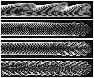
Composite images of (a) low- $Ca$ and (b) high-
 $Ca$ peeling fingers for different values of
 $Q$, showing the evolution of the interface. The dotted line indicates the axis of symmetry. The experiments are labelled with numbers from 0 to 6, which are in turn used in figure 4 to indicate data points corresponding to these experiments. Images were recorded at fixed time intervals of (from top): 1.2, 0.75, 0.50, 0.4, 0.25, 0.07, 0.05 s.

The deflection of the sheet was measured using a laser sheet projected across the width of the channel at the end of the ROI. This line was imaged at an oblique angle by a second camera ( $22.9\pm 0.2~\text{pixels}~\text{mm}^{-1}$; 40–160 f.p.s.). Membrane deflection at the midpoint of the channel, along with knowledge of the tip propagation speed were then used to reconstruct the profile of the sheet during reopening, as in figure 2(c). Behind the air–oil interface the channel inflates while far ahead the channel is still collapsed; hence, the interface advances into a tapered geometry, behind a wedge-shaped volume of fluid.
The size of this wedge decreases as  $Ca$ increases. At high
 $Ca$, the interface therefore lies within the strongly tapered region, with a printers’-like instability generating multiple viscous fingering perturbations along the tip as in figure 2(d); see, e.g., Ducloué et al. (Reference Ducloué, Hazel, Pihler-Puzović and Juel2017a), McEwan & Taylor (Reference McEwan and Taylor1966). Due to the curvature of the interface, these perturbations are advected away from the tip along trajectories instantaneously normal to the interface as it propagates, consistent with the kinematic boundary condition (Lajeunesse & Couder Reference Lajeunesse and Couder2000). Repeated shedding of perturbations produces complex spatio-temporal patterns, which we visualise using composite images generated from successive frames of a top-view recording, as shown in figure 2(d). Here, the pink trajectory obtained following Lajeunesse & Couder (Reference Lajeunesse and Couder2000) provides a close approximation to the path of the circled perturbation. The separation between advected perturbation trajectories reflects the rate at which perturbations were produced at the tip. Observations of pattern formation provided a sensitive measure of bubble pressure and capillary number, defined here as
 $Ca=\unicode[STIX]{x1D707}U/\unicode[STIX]{x1D70E}$. Small experimental variations in these parameters were clearly reflected in the pattern, and distinct patterns were associated with each mode of propagation.
3 Results
3.1 Peeling fingers
The experiments revealed a wide variety of finger morphologies, depending on the value of the flow rate, which either persisted or evolved over the ROI. Typical examples of the propagating fingers that persisted over the ROI are shown in figure 3. These steadily propagating fingers retained an approximately constant bubble pressure (i.e. with variations less than the experimental resolution of 10 Pa, see figure 2b). We consider persistent fingers stable in the sense that neither pattern nor pressure vary over the ROI.
In figure 4(a), we plot with cyan triangles the bubble pressure  $\overline{p}_{B}$ of all the persistent fingers as a function of the non-dimensional bubble speed
 $\overline{Ca}$. The overbars indicate time-averaged values over the ROI and the error bars indicate standard deviations. Note that the pressure error bars are generally not visible because they are smaller than the markers. The experimental points form two disconnected pressure lines, where
 $\overline{p}_{B}$ increases monotonically with
 $\overline{Ca}$, indicating that the stable fingers observed are peeling, consistent with previous numerical studies (Halpern et al. Reference Halpern, Naire, Jensen and Gaver2005). We refer to the two pressure lines, each highlighted with a solid grey line to guide the eye, as low-
 $Ca$ (open triangles) and high-
 $Ca$ (solid triangles) peeling lines, respectively. They are separated by an interval in capillary number,
 $0.1<\overline{Ca}<0.2$, where we do not observe stable fingers and record time-evolving patterns instead; see § 3.3. The pressure intervals spanned by the two peeling lines overlap in the range
 $85<\overline{p}_{B}<110~\text{Pa}$. This indicates a region of bi-stability where for a given bubble pressure, either low or high-
 $Ca$ stable finger propagation is possible.
The high- $Ca$ line, which is approximately linear in
 $\overline{Ca}$, appears to end abruptly at
 $\overline{Ca}\simeq 0.2$ and
 $\overline{p}_{B}\simeq 85~\text{Pa}$. This means that for either bubble pressure or capillary number values below these thresholds, only low-
 $Ca$ peeling fingers may be observed. The presence of a minimum on the high-
 $Ca$ line is reminiscent of the limit point separating stable peeling behaviour from unstable pushing behaviour in figure 1. We hypothesise the turning of the high-
 $Ca$ line at the minimum pressure value and its continuation as a line of unstable pushing fingers that extends over the interval
 $0.1\leqslant \overline{Ca}\leqslant 0.2$, as sketched in figure 1. We also refer to § 3.3 for a discussion of the red symbols in figure 4(a), which indicate fingers that evolve over the ROI.
(a) Bubble pressure  $\overline{p}_{B}$ as a function of capillary number
 $\overline{Ca}$, showing time-averaged data over the ROI for peeling fingers (triangles) and transient fingers (circles). Symmetric (asymmetric) fingers are indicated by filled (open) symbols, and error bars show the standard deviations of experimental measurements. Samples of finger shapes associated with different regions of the graph are shown with inset images. The band of pressures over which both peeling lines occur is shaded, as is the band of
 $\overline{Ca}$ over which no stable fingers are observed. The shaded curves are intended to guide the eye, indicating the structure of the steady peeling. (b) Here the data are extended to include strongly asymmetric modes observed at the lowest flow rates studied.

The two peeling lines are associated with different types of fingers, which are distinguished both by their respective symmetries about the centreline of the channel (figure 3), as well as the pattern-forming instability associated with each. The high- $Ca$ line denotes a symmetric peeling finger, which arises through the taper-induced instability described in § 2 (figure 3b). The small-amplitude fingering perturbation which generates this feathered pattern is characteristic of displacement flows in compliant geometries (Juel, Pihler-Puzović & Heil Reference Juel, Pihler-Puzović and Heil2018). These fingers are associated with significant variations of the bubble speed, as indicated by the horizontal error bars on the high-
 $Ca$ line in figure 4(a). We attribute these variations to small non-uniformities in the thickness of the fluid layer in the collapsed channel resulting from the small variations in the pre-stress applied to the elastic sheet along the channel. The sensitivity of this type of finger stems from its interface encroaching the most collapsed region of the channel; see also figure 5(b) in § 3.2. We note that similar variations were reported by Ducloué et al. (Reference Ducloué, Hazel, Thompson and Juel2017b) for channels collapsed beyond the point of opposite wall contact.
(a,b) Channel height measured along the centreline in the reopening region for (a) asymmetric and (b) symmetric peeling modes. The flow rate  $Q$ is given in each figure. The bubble pressure
 $\overline{p}_{B}$ is approximately constant, while the hydrostatic pressure
 $p_{HS}$ in the oil far ahead of the interface sets the initial collapse of the channel.
 $D_{tip}$ is the depth of the channel at the finger tip. The length of the fluid wedge,
 $L$, is taken as the distance between the finger tip and the nearest point (circled) at which the channel height reaches its collapsed height to within experimental resolution. (c) Fluid wedge length
 $L$ as a function of flow rate
 $Q$. Inset: in-plane channel height measured across the width
 $W$ of the channel, in the vicinity of the finger tip (outlined) for low flow rate experiments. The imposed level of initial collapse,
 $A_{i}=0.43$, corresponds to a collapsed channel height along its centreline of approximately 0.2 mm (dark blue). (d) Comparison between viscous and capillary effects for each peeling mode. The total pressure drop (triangles) is
 $p_{B}-p_{HS}$. The capillary pressure drop (circles) is taken to be
 $2\unicode[STIX]{x1D70E}/D_{tip}$.

Several finger morphologies are observed along the low- $Ca$ line in figure 4(a), which appears to be piecewise linear. Marker 2 in figure 4(a) is the first experimental point on the upper line segment of the low-
 $Ca$ line (distinguishable by its smaller slope; experiments performed at
 $11\leqslant Q\leqslant 30~\text{ml}~\text{min}^{-1}$). This point corresponds to a round-tipped peeling finger (figure 3a, experiment 2) with a slight asymmetry, quantified by an offset between the bubble tip and the channel centreline of
 $6\pm 1\,\%$ over the ROI. At larger flow rates, the tip of the finger flattens, exhibiting undulations along one side of the finger (figure 3a, experiment 3), before developing large indents on the interface due to tip splitting at yet higher values of
 $\overline{Ca}$ (figure 3a, experiment 4), which are reminiscent of instabilities observed in rigid channels; see § 3.2. The irregular patterns that form in figure 3(a) (experiment 4) suggest that tip splitting is triggered by background perturbations in the system. The steeper line segment observed for the lowest values of
 $\overline{Ca}$ shown in figure 4(a) is associated with a strongly asymmetric finger that becomes increasingly localised along the edge of the channel as the flow rate is reduced (see figure 3a, experiment 1; experiments performed at
 $9\leqslant Q\leqslant 10.5~\text{ml}~\text{min}^{-1}$ compared to experiment 2). We find evidence of an abrupt transition between fingers of distinct morphologies in the vicinity of experiment 2; see § 3.2.
All the experimental points shown on the low- $Ca$ line in figure 4(a) correspond to approximately steadily propagating fingers; in each case we observed variations in pressure within a 10 Pa range, indicative of small variations in the sheet pre-stress. However, experiments performed for lower flow rates of
 $2\leqslant Q<9~\text{ml}~\text{min}^{-1}$ yielded asymmetric fingers (figure 3a, experiment 0) whose bubble pressure decreased monotonically along the ROI, contrary to all other peeling modes; see § 3.2. Their average pressure variation with
 $\overline{Ca}$ is shown in figure 4(b). The minimum bubble pressure recorded during propagation was less than -40 Pa, below atmospheric pressure but still in excess of
 $p_{HS}\approx -160~\text{Pa}$,
 $p_{HS}$ being the pressure far ahead of the interface, imposed hydrostatically in order to set the initial channel collapse. We did not find evidence within the range of flow rates investigated that a minimum pressure value needs to be exceeded in order for finger propagation to occur on the lower-
 $Ca$ line in contrast with the high-
 $Ca$ line. These observations extend the findings of previous models of airway reopening which did not capture low-pressure asymmetric finger propagation because they were constrained to support only symmetric modes (Hazel & Heil Reference Hazel and Heil2003; Halpern et al. Reference Halpern, Naire, Jensen and Gaver2005).
3.2 Viscous versus elastic reopening
The evolution of the finger morphology and channel inflation as  $Q$ is varied reflects a complex two-way fluid–structure interaction, and we are not aware of simple scaling arguments that may predict the linear relationships between
 $\overline{p}_{B}$ and
 $\overline{Ca}$ shown in figure 4. However, the distinction between the low and high-
 $Ca$ peeling fingers can be interpreted qualitatively in terms of the dominance of viscous and elastic effects, respectively. For instance, the tip-splitting instabilities observed at low
 $\overline{Ca}$ (figure 3a, experiment 4) are similar to those observed in rigid channels (Tabeling et al. Reference Tabeling, Zocchi and Libchaber1987), indicating insensitivity to the channel’s tapered geometry. To understand this quantitatively we consider the size of the fluid wedge ahead of the interface for both low and high-
 $Ca$ peeling in figure 5(a,b), by plotting the reopening profile along the centreline of the channel. The volume of the fluid wedge ahead of the finger tip is significantly larger for low-
 $Ca$ peeling. As a result, the effects of the compliance-induced taper are diminished and the flow is dominated by viscous forces within the wedge. The asymmetric shape of the fingers at low
 $Ca$ is then a consequence of the central constriction of the channel ahead of the interface, which is associated with a quartic profile of the collapsed sheet in the transverse cross-section (Ducloué et al. Reference Ducloué, Hazel, Thompson and Juel2017b). In rigid channels with a similar geometry, it has been shown that asymmetric fingers minimise viscous dissipation by driving flow predominantly in the less constricted sections of the channel (Franco-Gómez et al. Reference Franco-Gómez, Thompson, Hazel and Juel2016).
The length of the fluid wedge measured along the centreline of the channel is defined in figure 5(a) and shown as a function of  $Q$ in figure 5(c). High-
 $Ca$ peeling fingers (
 $Q\geqslant 90~\text{ml}~\text{min}^{-1}$) are associated with a constant fluid wedge length with
 $L\simeq 0$. This means that the finger shape is strongly influenced by the compliance-induced taper of the reopening region. For low-
 $Ca$ peeling fingers driven by flow rates
 $Q\geqslant 11~\text{ml}~\text{min}^{-1}$ (figure 3(a), experiments 2–4) the length
 $L$ of the fluid wedge decreases monotonically with increasing
 $Q$. The visible offset from the centreline of the peeling fingers observed for
 $Q<11~\text{ml}~\text{min}^{-1}$ means that measurements of sheet deflection within the plane of the channel are more appropriate to gauge the fluid distribution around the finger tip, as shown in the insets of figure 5(c). They indicate a significant reduction in the depth of fluid ahead of the finger from the approximately centred mode at
 $Q=11~\text{ml}~\text{min}^{-1}$ to the off-centred mode at
 $Q=10.5~\text{ml}~\text{min}^{-1}$, suggesting a transition between fingers of distinct characteristics over this interval. As
 $Q$ is further reduced (wall-adjacent mode at
 $Q=5~\text{ml}~\text{min}^{-1}$ in figure 5c), the elastic sheet hardly inflates around the finger tip and bubble pressures are close to or below atmospheric pressure; see figure 4(b). This suggests that fluid is driven along the length of the channel, within the less-collapsed regions close to the walls, as though the channel were effectively rigid; this conjecture is supported by the monotonic drop in bubble pressure
 $p_{B}$ observed over the ROI for these experiments (see § 3.1), which would be expected for displacement flows at fixed
 $Q$ within a rigid pipe open the atmosphere at the outlet.
Further evidence is provided by the contribution of capillary pressure to the reopening pressure  $\overline{p}_{B}-p_{HS}$ which we plot in figure 5(d) as a function of the flow rate
 $Q$. The contribution to the reopening pressure due to capillarity is taken to be the Laplace pressure drop
 $\unicode[STIX]{x1D70E}\unicode[STIX]{x1D705}$ across the interface with the curvature approximated by
 $\unicode[STIX]{x1D705}\approx 2/D_{tip}$,
 $D_{tip}$ being the local channel depth at the interface. This is because in our large aspect ratio channel this curvature is always significantly larger than the in-plane curvature. For low-
 $Ca$ peeling fingers, the capillary contribution to the bubble pressure is relatively small and so a large viscous pressure drop must be present ahead of the finger tip, consistent with the large volume of fluid separating the finger tip from the most collapsed region of the channel as highlighted in figure 5(a). For high-
 $Ca$ peeling fingers, however, the two terms are of approximately equal magnitude suggesting a negligible viscous pressure drop. This is consistent with the encroaching of the fluid interface into the most collapsed region of the channel highlighted in figure 5(b) and suggests a significant contribution of capillary forces to the finger shape. In a related study performed in the limit of extreme collapse, Ducloué et al. (Reference Ducloué, Hazel, Thompson and Juel2017b) argued that low and high-
 $Ca$ peeling lines corresponded to viscous- and elastic-dominated reopening, respectively. To an extent, our results support this interpretation, particularly for experiments performed at the highest (
 $Q\geqslant 90~\text{ml}~\text{min}^{-1}$) and lowest (
 $Q<9~\text{ml}~\text{min}^{-1}$) flow rates. However, for measurements taken at intermediate flow rates
 $9\leqslant Q\leqslant 30~\text{ml}~\text{min}^{-1}$, the gradual reduction in the length of the fluid wedge suggests that the influence of elastic effects progressively increases relative to viscous effects with increasing
 $Q$, and that neither effect can be considered entirely dominant.
3.3 Transient fingers
We have seen in figure 4 that the two lines of stable peeling fingers are separated by a range of  $\overline{Ca}$ where we do not observe stable finger propagation. Instead, we find that fingers initiated within that range by imposing values of
 $Q$ in the range
 $28\leqslant Q\leqslant 70~\text{ml}~\text{min}^{-1}$ evolve towards stable peeling fingers on either line through a series of different finger shapes. In figure 6, we show the evolution of bubble pressure and
 $Ca$ during the propagation of two typical transient fingers. The total pressure variation of up to 40 Pa exceeds the maximum of 10 Pa observed during the propagation of stable peeling fingers. The precise details of the evolution are different in the two graphs but in both cases, it suggests that the fingers undergo non-trivial organised transient behaviour. A key observation is that the pressure initially increases while
 $Ca$ decreases. This is a signature of pushing dynamics predicted numerically Halpern et al. (Reference Halpern, Naire, Jensen and Gaver2005), which in our experiment was found to initiate the evolution of all transient fingers. We conjecture that the complex time-dependent behaviours of the transient fingers can be interpreted as a transient exploration of the stable manifolds of weakly unstable propagation modes, as recently demonstrated in the context of finite bubble propagation in rigid Hele-Shaw channels (Franco-Gómez et al. Reference Franco-Gómez, Thompson, Hazel and Juel2018; Keeler et al. Reference Keeler, Thompson, Lemoult, Juel and Hazel2019). This interpretation points to the existence of an unstable steady pushing finger, which was previously hypothesised in § 3.1.
Figure 7(a) shows composite images from four representative experiments initiated for values of  $Ca$ in the unstable region, which show the complex organised finger evolution previously identified in figure 6 for experiments 7 and 9. In experiments 7–9, the initial pushing behaviour is associated with symmetric fingers (first interface highlighted in red). The finger evolution presented in experiment 10 also suggests initial pushing behaviour but in this case the pushing finger (first interface highlighted in red) appear slightly asymmetric about the centreline of the channel. Figure 7(b) provides a
 $p_{B}{-}Ca$ phase-plane representation of the transient evolution of the fingers shown in figure 7(a). Grey solid lines indicate the low and high-
 $Ca$ lines of stable peeling fingers identified in figure 4. Phase-plane trajectories are shown with dashed grey lines for each experiment and the direction of evolution is indicated with black arrowheads. Symbols of different colours are used to indicate specific finger-tip morphologies that occur at the marked points on the trajectories, and these match the highlighted interfaces in figure 7(a). A summary of the finger shapes identified is provided in a series of inset images in figure 7(b).
Capillary number  $Ca$ and bubble pressure
 $p_{B}$ as a function of the position
 $x$ of the tip of the air finger within the region of interest, plotted for two transient modes at fixed flow rate
 $Q$. For all transient modes, we observe a significant rise in
 $p_{B}$, initially accompanied by a decrease in
 $Ca$ – a defining characteristic of pushing modes. (a,b) Correspond to experiments 7 and 9 in figure 7. The vertical axes in (a) and (b) do not share the same scales.

(a) Composite images showing the transient evolution of fingers at different values of the flow rate  $Q$ towards either low or high-
 $Ca$ stable peeling fingers. Images were recorded at fixed time intervals of (from top): 0.28, 0.20, 0.26, 0.26 s. (b) Trajectories in the
 $p_{B}{-}Ca$ phase plane depicting the finger evolution for each experiment shown in (a). The black arrowheads indicate increasing time, and the symbols mark specific points of the evolution that match the highlighted interfaces in (a). The shaded curves indicate the low and high-
 $Ca$ lines of stable peeling fingers identified in figure 4. The finger shapes identified by the symbols are summarised in a series of inset images.

At low  $Q$ (e.g., experiment 7 in figure 7 where
 $Q=28~\text{ml}~\text{min}^{-1}$) the system rapidly evolves towards a low-
 $Ca$ stable peeling finger via pushing dynamics (i.e.
 $p_{B}$ increases while
 $Ca$ decreases). Upon reaching the low-
 $Ca$ peeling line, the bubble pressure starts to increase with
 $Ca$, thus climbing along the peeling line, and we observe tip splitting. Over the final third of the ROI,
 $p_{B}$ reaches an approximately constant value (see figure 6a), which suggests that the system may be approaching a stable state, although
 $Ca$ is still adjusting non-monotonically.
At flow rates  $Q>46~\text{ml}~\text{min}^{-1}$ (e.g. experiments 9 and 10) the system does not converge onto the low-
 $Ca$ peeling line. Instead, the system initially follows orbital trajectories, similar to the relaxation oscillations described by Halpern et al. (Reference Halpern, Naire, Jensen and Gaver2005) for pushing modes in an analogous 2-D system where the in-plane interfacial structure is absent. The mechanisms responsible are likely similar; during the initial phase of pushing dynamics, the depth of the fluid wedge ahead of the interface increases as fluid is accumulated. This yields a reduction in viscous resistance in this region, and the tip abruptly accelerates as a result. During this second phase, the curvature of the finger tip increases further, an adaptation which would reduce viscous resistance, allowing fluid in the wedge to escape past the tip. This is followed by a third phase where both bubble pressure and
 $Ca$ decrease, suggesting peeling dynamics; see also figure 6(b) for
 $x>150~\text{mm}$. Undulating structures are generated along the previously flat sections of interface either side of the tip (squares in figure 7b) forming an interface shape which is distinct from stable peeling fingers and may be indicative of the existence of an unstable peeling finger. The dynamics of the system up to this point appears to be dominated exclusively by unstable modes. The final phase of the transient evolution is an abrupt acceleration towards the high-
 $Ca$ peeling line. This dynamics is robust, qualitatively describing all experiments at
 $Q>46~\text{ml}~\text{min}^{-1}$.
A distinct dynamical behaviour is observed in experiment 8. At  $Q=45~\text{ml}~\text{min}^{-1}$, the initial pushing dynamics drives the finger towards the low-
 $Ca$ peeling line at around the maximum bubble pressure recorded for stable peeling fingers. The system therefore fails to stabilise and is instead repelled back towards the high-
 $Ca$ line of stable peeling fingers via a succession of interface shapes, first asymmetric then symmetric. We note that the behaviour of experiment 8 is only observed over a narrow range of
 $Q$. At slightly greater or lower
 $Q$, the system transitions directly to either low or high-
 $Ca$ stable peeling. Hence, the results of figure 7 suggest that the conjectured pushing mode acts as an organising structure, guiding the system towards either of the stable states. This behaviour is reminiscent of that of an edge state of the system, which in the context of fluid mechanics is an invariant solution of the governing equations that has only a small number of unstable eigenvalues and whose stable manifold forms the ‘boundary’ between two qualitatively different dynamical outcomes (Gallino et al. Reference Gallino, Schneider and Gallaire2018; Keeler et al. Reference Keeler, Thompson, Lemoult, Juel and Hazel2019).
Finally, we return to figure 4(a), where the experiments exhibiting evolving finger morphologies are shown with red circles and the error bars quantify the variations in pressure and  $Ca$ as the finger propagates over the ROI. The solid circles indicate experiments where a symmetric pushing finger was observed transiently, while the open circles are associated with the asymmetric pushing fingers described above in the context of experiment 10. The solid circles fall on the upper segment of the low-
 $Ca$ line of stable peeling fingers for the lowest values of
 $\overline{Ca}$. This is because in this region the transient dynamics occurs over a relatively small section of the ROI so that the average is dominated by the final peeling behaviour. For
 $0.1\leqslant \overline{Ca}\leqslant 0.2$, the solid circles show a clear trend for the average bubble pressure to decrease with increasing
 $\overline{Ca}$, apparently outlining a line of unstable pushing fingers. However, caution is required when interpreting this data. If a longer ROI were available, we would expect averages to be dominated by the final peeling state and thus approach the high-
 $Ca$ line of stable peeling fingers. However, these points represent fingers which evolve over the entire ROI and because of the approximately orbital nature of the transients, the trend in the time-averaged data primarily reflects the fact that over this parameter range, an increase in the imposed flow rate
 $Q$ results in an increase in the initial value of
 $Ca$, while the initial
 $p_{B}$ is reduced. The spontaneous selection of initial conditions consistent with a pushing branch provides further support for the conjectured existence of an unstable steady pushing finger.
4 Conclusion
We have investigated a benchtop model of airway reopening experimentally, where air is injected with constant flow rate into a liquid-filled Hele-Shaw channel topped with an elastic lid. The elastic sheet that forms the upper boundary of the channel is collapsed into a quartic profile prior to experimentation by reducing the pressure inside the channel to below atmospheric pressure. We focus on large initial collapse of the channel, so that the maximum deflection of the sheet is close to the depth of the undeformed channel and depth variations within the cross-section are significant. This regime is motivated by pulmonary airway reopening where liquid-filled compliant airways are believed to be extensively collapsed prior to the first breath of a baby (Bland Reference Bland2001).
In contrast with previous numerical models of airway reopening, we do not find that a minimum pressure needs to be exceeded in order for an air finger to propagate. Consistent with previous experimental studies of related systems, we observe multiple modes of propagation which differ by the instabilities of the finger tip and its symmetry about the centreline of the channel. We identify two separate lines of stable peeling fingers, mediated over a region of bistability by unstable pushing behaviour. Hence, depending on the initial values of bubble pressure and capillary number, the system may evolve transiently to reach stable steadily propagating fingers associated with either peeling line. We are able to explore this dynamics experimentally by direct observation of the interface because the nonlinearity of this fluid–structure interaction system is contained entirely within the interface and elastic sheet. Furthermore, our measurements provide evidence of the important role of unstable states in the transient evolution of this conceptually simple front-propagating system. Numerical simulations of a fully coupled 2-D fluid–structure interaction model of the system are currently underway and preliminary findings indicate a rich multiplicity of both stable and unstable modes of finger propagation. However, it remains a significant challenge to the numerical model to capture the intricate finger shapes and rich dynamics identified experimentally in this paper.
Acknowledgements
The authors thank A. L. Hazel for many helpful discussions. The work of C.C. was supported by an EPSRC PhD studentship, D.P.-P. was funded through EPSRC grant EP/R045364/1 and A.J. through EPSRC grant EP/P026044/1.
Declaration of interests
The authors report no conflict of interest.


 Open access

