



1 Introduction
Diffraction of light was first reported in the form of a light beam bending around obstacles or through slits in a thin sheet (Grimaldi Reference Grimaldi1665). In the classical wave theory of light, the diffraction from a slit can be rationalized in terms of the Huygens–Fresnel principle, according to which the diffraction pattern results from the superposition of spherical wave sources placed along the slit width (Born & Wolf Reference Born and Wolf2000). This superposition results in interference between the waves, the net effect of which is the creation of maxima and minima of intensity, the so-called diffraction fringes. For a monochromatic plane wave of light of wavelength
 $\unicode[STIX]{x1D706}$
incident on a thin slit of width
 $L$
, the position of intensity peaks on a screen placed at a distance
 $L_{s}\gg L^{2}/\unicode[STIX]{x1D706}$
(the Fraunhofer limit) varies with the ratio
 $\unicode[STIX]{x1D706}/L$
. The overall intensity on the screen as a function of the diffraction angle
 $\unicode[STIX]{x1D6FC}$
measured with respect to the slit centreline takes the form
 $$\begin{eqnarray}I(\unicode[STIX]{x1D6FC})=I_{0}\left(\frac{\sin (\unicode[STIX]{x03C0}L\sin \unicode[STIX]{x1D6FC}/\unicode[STIX]{x1D706})}{\unicode[STIX]{x03C0}L\sin \unicode[STIX]{x1D6FC}/\unicode[STIX]{x1D706}}\right)^{2}.\end{eqnarray}$$
In the double-slit geometry, wherein thin slits of width
 $L$
are separated by a distance
 $d\ll L_{s}$
, interference results from the superposition of the wave fields emerging from the two slits, and the position of the peaks varies with both
 $\unicode[STIX]{x1D706}/L$
and
 $\unicode[STIX]{x1D706}/d$
in the Fraunhofer limit. The resulting intensity on a distant screen is given by
 $$\begin{eqnarray}I(\unicode[STIX]{x1D6FC})=I_{0}\left(\frac{\sin (\unicode[STIX]{x03C0}L\sin \unicode[STIX]{x1D6FC}/\unicode[STIX]{x1D706})}{\unicode[STIX]{x03C0}L\sin \unicode[STIX]{x1D6FC}/\unicode[STIX]{x1D706}}\cos (\unicode[STIX]{x03C0}d\sin \unicode[STIX]{x1D6FC}/\unicode[STIX]{x1D706})\right)^{2}.\end{eqnarray}$$
Single-particle diffraction and interference have been experimentally challenging problems since the introduction of the concept of light quanta by Planck (Reference Planck1901) and Einstein (Reference Einstein1905). In these experiments, microscopic particles are detected as localized points on a screen, and their distribution on the screen after many realizations of the same experiment is proportional to the intensity of an incident plane wave diffracted by the same apparatus. Taylor (Reference Taylor1909) showed that the diffraction pattern of light from a needle is unaltered if its intensity is reduced to a few light quanta. A double-slit experiment with single photons was first reported by Tsuchiya et al. (Reference Tsuchiya, Inuzuka, Kurono and Hosoda1985). The build-up of an electron interference pattern with single electrons passing through an electron biprism was first reported by Tonomura et al. (Reference Tonomura, Endo, Matsuda and Kawasaki1989), and only recently in a double-slit geometry by Bach et al. (Reference Bach, Pope, Liou and Batelaan2013). While quantum mechanics correctly predicts the probability distribution of particles on the screen, corresponding to the single-particle interference pattern, it does not provide any physical mechanism that might account for the observed diffraction patterns. These conceptual difficulties, which continue to motivate both experimental (Kocsis et al. Reference Kocsis, Braverman, Ravets, Stevens, Mirin, Shalm and Steinberg2011) and theoretical (Aharonov et al. Reference Aharonov, Cohen, Colombo, Landsberger, Sabadini, Struppa and Tollaksen2017) developments, were highlighted by Feynman in his discussion of the double-slit experiment with electrons, ‘what is the machinery behind the law? …We have no ideas about a more basic mechanism from which these results can be deduced’ (Feynman, Leighton & Sands Reference Feynman, Leighton and Sands1963).
One such mechanism was proposed by Louis de Broglie in the 1920s. De Broglie (Reference de Broglie1924) hypothesized a wavelength for matter particles, on the basis of which he predicted electron diffraction, as was confirmed experimentally by Davisson & Germer (Reference Davisson and Germer1927) and later by Jönsson (Reference Jönsson1961) for interference from multiple slits. In his ‘double-solution theory’, de Broglie (Reference de Broglie1960, Reference de Broglie1987) considered two waves: a real pilot wave centred on the particle and the statistical wave of standard quantum theory. He proposed that the pilot wave responsible for guiding the particle originates from internal particle vibration characterized by an exchange between the particle rest mass energy and wave energy. Another key feature of de Broglie’s mechanics was the so-called ‘harmony of phases’, according to which the particle and wave remain in resonance: the internal vibration of the particle is synchronized with its pilot wave. De Broglie imagined quantum particles propagating normal to planes of equal phase of the pilot wave; thus, the slit-induced diffraction of the guiding wave provides a framework for understanding fringes even in the case of single-particle interference (de Broglie Reference de Broglie1926). On the strength of its ability to rationalize single-particle diffraction and interference, Bell (Reference Bell1987) said of de Broglie’s mechanics ‘it is a great mystery to me that it was so generally ignored’.
De Broglie’s pilot-wave theory has attracted attention from the fluid mechanics community in the last decade, since Yves Couder and coworkers discovered that a droplet bouncing on the surface of a vibrating fluid bath can self-propel through a resonant interaction with its own wave field (Couder et al. Reference Couder, Protière, Fort and Boudaoud2005; Protière, Boudaoud & Couder Reference Protière, Boudaoud and Couder2006). These walking droplets or ‘walkers’, comprising a droplet and its guiding wave, have been shown to exhibit several features reminiscent of quantum particles (Bush Reference Bush2015), including quantized orbits (Fort et al. Reference Fort, Eddi, Boudaoud, Moukhtar and Couder2010; Harris & Bush Reference Harris and Bush2014; Labousse et al. Reference Labousse, Perrard, Couder and Fort2014, Reference Labousse, Oza, Perrard and Bush2016a ; Perrard et al. Reference Perrard, Labousse, Miskin, Fort and Couder2014; Oza et al. Reference Oza, Harris, Rosales and Bush2014a ,Reference Oza, Wind-Willassen, Harris, Rosales and Bush b ) and orbital-level splitting (Eddi et al. Reference Eddi, Moukhtar, Perrard, Fort and Couder2012), tunnelling over submerged barriers (Eddi et al. Reference Eddi, Fort, Moisy and Couder2009; Carmigniani et al. Reference Carmigniani, Lapointe, Symon and McKeon2014; Nachbin, Milewski & Bush Reference Nachbin, Milewski and Bush2017) and wavelike statistics in confined geometries (Harris et al. Reference Harris, Moukhtar, Fort, Couder and Bush2013; Gilet Reference Gilet2014; Sáenz et al. Reference Sáenz, Cristea-Platon and Bush2017). More recently, Filoux et al. (Reference Filoux, Hubert, Schlagheck and Vandewalle2017) have investigated the behaviour of walking droplets in linear channels and proposed an analogy with waveguides.
The possibility of the walking droplet system as a hydrodynamic quantum analogue was launched by the ingenious experiments of Couder & Fort (Reference Couder and Fort2006), who reported that walkers exhibit single-particle diffraction and interference when passing through apertures between submerged barriers (Couder & Fort Reference Couder and Fort2006, Reference Couder and Fort2012). They sent single walkers towards a submerged barrier with openings on the scale of the guiding wavelength (figure 2
a). As the walker passed through the aperture, its trajectory was deviated by an angle
 $\unicode[STIX]{x1D6FC}$
due to the distortion of its pilot wave. The authors pointed out that this deflection could be interpreted in terms of an effective position–momentum uncertainty relation for the walkers: when confined spatially, the momentum in the direction of confinement becomes uncertain due to the distortion of the guiding wave. The impact parameter
 $y_{i}$
, defined as the location of the incident trajectory of the walker relative to the centreline of the slit (figure 2), was varied so as to uniformly span the slit, in order to best approximate an incident plane wave. The main conclusions of Couder & Fort (Reference Couder and Fort2006) can be summarized as follows.
-
(i) The deflection angle
 $\unicode[STIX]{x1D6FC}$
is independent of the impact parameter
$y_{i}$
.
-
(ii) The emerging statistical pattern corresponds roughly to the amplitude (rather than the intensity, as is the case in quantum mechanics) of the Fraunhofer diffraction of a monochromatic plane wave impinging on the slits. Specifically, the amplitude for the single slit was
(1.3)while for the double slit
$$\begin{eqnarray}f(\unicode[STIX]{x1D6FC})=A\left|\frac{\sin (\unicode[STIX]{x03C0}L\sin \unicode[STIX]{x1D6FC}/\unicode[STIX]{x1D706}_{F})}{\unicode[STIX]{x03C0}L\sin \unicode[STIX]{x1D6FC}/\unicode[STIX]{x1D706}_{F}}\right|,\end{eqnarray}$$
(1.4)where
$$\begin{eqnarray}f(\unicode[STIX]{x1D6FC})=A\left|\frac{\sin (\unicode[STIX]{x03C0}L\sin \unicode[STIX]{x1D6FC}/\unicode[STIX]{x1D706}_{F})}{\unicode[STIX]{x03C0}L\sin \unicode[STIX]{x1D6FC}/\unicode[STIX]{x1D706}_{F}}\cos (\unicode[STIX]{x03C0}d\sin \unicode[STIX]{x1D6FC}/\unicode[STIX]{x1D706}_{F})\right|,\end{eqnarray}$$
$\unicode[STIX]{x1D706}_{F}$
is the Faraday wavelength.
-
(iii) The wave passes through both slits and the interaction of the resulting waves affects the trajectory of the walker.




The experimental results of Couder & Fort (Reference Couder and Fort2006) in the single-slit geometry were roughly reproduced by numerical simulations in which the walls were modelled by periodically spaced secondary wave sources. Details of this image system were not specified. Key experimental parameters, such as the forcing amplitude and the fluid depth above the barriers, were not reported; only an approximate drop diameter
 $D\approx 1$
mm was reported. Moreover, the system was not isolated from ambient air currents. Their results have yet to be convincingly reproduced despite several experimental (Andersen et al.
Reference Andersen, Madsen, Reichelt, Ahl, Lautrup, Ellegaard, Levinsen and Bohr2015; Harris Reference Harris2015; Batelaan et al.
Reference Batelaan, Jones, Huang and Bach2016) and theoretical (Dubertrand et al.
Reference Dubertrand, Hubert, Schlagheck, Vandewalle, Bastin and Martin2016) attempts.
The results of Couder & Fort (Reference Couder and Fort2006) have been contested by Andersen et al. (Reference Andersen, Madsen, Reichelt, Ahl, Lautrup, Ellegaard, Levinsen and Bohr2015) and Bohr, Andersen & Lautrup (Reference Bohr, Andersen, Lautrup and Klapp2016) on the following grounds. First, they found experimental results at odds with those of Couder & Fort. Specifically, they observed a strong correlation between the diffraction angle
 $\unicode[STIX]{x1D6FC}$
and the impact parameter
 $y_{i}$
, and no clear diffraction or interference pattern was apparent. Second, they pointed out that in the double-slit experiment of Couder & Fort (Reference Couder and Fort2006), the limited amount of data (75 independent trajectories) was insufficient to conclude that an interference pattern emerged: the fit with a Gaussian distribution was as good as that with the amplitude of a Fraunhofer diffraction pattern (1.4). Third, their calculation of the persistence time of waves in the bath suggested that it is comparable to the passage time of the drop through a slit, casting doubt on the influence of the second slit in the double-slit geometry. Fourth, they suggested a fundamental difference between the walker and quantum systems on the basis of a double-slit thought experiment, in which a splitter plate is placed ahead of the slits. They asserted that the quantum system would maintain wave coherence in the presence of the splitter plate, and then exhibit interference, while such would clearly not be the case for the walking droplet system.
Since the original experiments of Couder & Fort (Reference Couder and Fort2006), our understanding of the walker system has progressed considerably. In particular, it is now clear that the walker dynamics is extremely sensitive to both the droplet size and the forcing amplitude (Protière et al.
Reference Protière, Boudaoud and Couder2006; Eddi et al.
Reference Eddi, Terwagne, Fort and Couder2008; Wind-Willassen et al.
Reference Wind-Willassen, Moláček, Harris and Bush2013; Moláček & Bush Reference Moláček and Bush2013a
,Reference Moláček and Bush
b
), neither of which was accurately reported by Couder & Fort (Reference Couder and Fort2006). Several recent technical advances have allowed for more repeatable experiments. First, Harris, Liu & Bush (Reference Harris, Liu and Bush2015) constructed a piezoelectric droplet generator that allows for precise control of the droplet size. Second, Harris & Bush (Reference Harris and Bush2015) designed a precision driver that provides spatially uniform vibration to the bath, as is essential for repeatable investigations at high forcing acceleration. Recent theoretical developments account effectively for the drop dynamics in the presence of submerged boundaries (Faria Reference Faria2017). The refined experimental set-up was recently used in conjunction with the theoretical model of Faria (Reference Faria2017) to demonstrate that the reflection of a walking droplet from a submerged barrier is non-specular. Specifically, the angle of reflection differs from the angle of incidence, and the walkers tend to be reflected at a fixed angle, between
 $60^{\circ }$
and
 $80^{\circ }$
with respect to the normal to the barrier (Pucci et al.
Reference Pucci, Sáenz, Faria and Bush2016).
We here present a combined experimental and theoretical study of walking droplets interacting with single and double slits. In § 2, we describe the experimental set-up and explain our choice of experimental parameters. We demonstrate the importance of isolating the system from ambient air currents and present our experimental results in single- and double-slit geometries. We demonstrate that the interaction of walking droplets with both single and double slits is dominated by a wall effect, similar to that arising when a walker is reflected from a planar submerged barrier (Pucci et al. Reference Pucci, Sáenz, Faria and Bush2016). In § 3, we summarize the theoretical model of Faria (Reference Faria2017) and present the theoretical results for walker diffraction past a single slit, a double slit and an edge. In § 4, we address the criticisms of the experiments of Couder & Fort (Reference Couder and Fort2006) raised by Andersen et al. (Reference Andersen, Madsen, Reichelt, Ahl, Lautrup, Ellegaard, Levinsen and Bohr2015), and point out the shortcomings of both studies in light of our relatively comprehensive experimental and theoretical investigation.
2 Experiments
2.1 Experimental set-up
The bath and droplet are composed of pure 20 cSt silicone oil with density
 $\unicode[STIX]{x1D70C}=950~\text{kg}~\text{m}^{-3}$
and surface tension
 $\unicode[STIX]{x1D70E}=20.6~\text{dynes}~\text{cm}^{-1}$
. The circular bath of diameter 16 cm is surrounded by a shallow border of width 9 mm and depth 1.5 mm. This shallow region serves to damp the waves generated by the oscillating meniscus at the edge of the container, thereby minimizing wave reflection and so limiting the range of influence of the outer boundary (Eddi et al.
Reference Eddi, Fort, Moisy and Couder2009; Harris & Bush Reference Harris and Bush2014). The bath is driven sinusoidally with frequency
 $f=80$
Hz and peak acceleration
 $\unicode[STIX]{x1D6FE}$
by an electromagnetic shaker guided by a linear air bearing which provides vertical vibration that is spatially uniform to within 0.1 % (Harris & Bush Reference Harris and Bush2015). The forcing is maintained at a constant acceleration amplitude to within
 $\pm 0.002g$
(where
 $g$
is the gravitational acceleration) using closed-loop feedback control. Above the Faraday threshold,
 $\unicode[STIX]{x1D6FE}_{F}$
, subharmonic standing waves form spontaneously on the free surface of the vibrating bath (Faraday Reference Faraday1831) with a typical wavelength determined by the standard water-wave dispersion relation (Benjamin & Ursell Reference Benjamin and Ursell1954), here
 $\unicode[STIX]{x1D706}_{F}=4.75$
mm.
The Faraday threshold is measured every 20 min as follows. We first set
 $\unicode[STIX]{x1D6FE}$
slightly above
 $\unicode[STIX]{x1D6FE}_{F}$
, then decrease it by
 $0.005g$
every minute. When the waves disappear, as visualized readily by a reflected light source, we take the Faraday threshold as the last recorded value of the acceleration. This procedure yields an uncertainty in
 $\unicode[STIX]{x1D6FE}_{F}$
of
 $\pm 0.005g$
. The sum of the relative errors of
 $\unicode[STIX]{x1D6FE}$
and
 $\unicode[STIX]{x1D6FE}_{F}$
gives a maximum uncertainty in
 $\unicode[STIX]{x1D6FE}/\unicode[STIX]{x1D6FE}_{F}$
of 0.002. In the experiments closest to the Faraday threshold, at
 $\unicode[STIX]{x1D6FE}/\unicode[STIX]{x1D6FE}_{F}=0.998\pm 0.002$
, we continuously checked that the bath was quiescent in the absence of a drop, that the system was below the Faraday threshold at all times and throughout the bath. We henceforth refer to the experimental control parameter
 $\unicode[STIX]{x1D6FE}/\unicode[STIX]{x1D6FE}_{F}$
as the memory. (We note that early theoretical formulations of the problem (Eddi et al.
Reference Eddi, Sultan, Moukhtar, Fort, Rossi and Couder2011; Moláček & Bush Reference Moláček and Bush2013b
) defined the characteristic decay time of the waves as the memory time
 $T_{M}(\unicode[STIX]{x1D6FE})=T_{d}/(1-\unicode[STIX]{x1D6FE}/\unicode[STIX]{x1D6FE}_{F})$
, where
 $T_{d}\sim 1/\unicode[STIX]{x1D708}{k_{F}}^{2}$
is the viscous decay time of the waves in the absence of forcing. These models approximate the waves as linear Faraday waves damped exclusively by the action of viscosity. When
 $\unicode[STIX]{x1D6FE}\rightarrow \unicode[STIX]{x1D6FE}_{F}$
(and
 $T_{M}$
diverges), this approximation breaks down and nonlinear wave effects become significant. The memory time
 $T_{M}$
appears nowhere in our theoretical formulation.) The threshold
 $\unicode[STIX]{x1D6FE}_{F}$
is always in the range
 $\unicode[STIX]{x1D6FE}_{F}=(4.18-4.23)g$
, with the variation resulting from the sensitivity of the fluid viscosity to temperature (Bechhoefer et al.
Reference Bechhoefer, Ego, Manneville and Johnson1995; Harris & Bush Reference Harris and Bush2014).
We note an important point for future experimental investigations of the walking droplet system. Curved trajectories in the absence of barriers may be taken as an indication of air currents, non-uniform vibration, operating above the Faraday threshold, or interactions with the cell boundaries. Thus, a simple but critical test is to send the walker across the cell in the absence of barriers (i.e. with the slit barriers removed) and check that it executes rectilinear motion. We verified this to be the case in our system for all values of forcing considered.
(a) Regime diagram indicating the dependence of the drop bouncing or walking state on the forcing amplitude
 $\unicode[STIX]{x1D6FE}/g$
and the vibration number
 $\unicode[STIX]{x1D6FA}=2\unicode[STIX]{x03C0}f\sqrt{\unicode[STIX]{x1D70C}D^{3}/8\unicode[STIX]{x1D70E}}$
(Wind-Willassen et al.
Reference Wind-Willassen, Moláček, Harris and Bush2013; Bush Reference Bush2015). In the
 $(m,n)$
bouncing or walking mode, the drop bounces
 $n$
times in
 $m$
driving periods. The range of walkers considered in this work, of diameter
 $D=0.67$
mm, is indicated by the white line as arising entirely within the chaotic walking regime. (b) Visualization of the wave field of a walker as it passes through the single slit (see supplementary movie 1 available at https://doi.org/10.1017/jfm.2017.790). (c,d) Trajectories of a walking droplet of diameter
 $D=0.80$
mm passing through the slit. For both panels, the impact parameter and experimental parameters are the same, the forcing amplitude is
 $\unicode[STIX]{x1D6FE}/\unicode[STIX]{x1D6FE}_{F}=0.95$
and the free speed of the walker is
 $u_{o}=12~\text{mm}~\text{s}^{-1}$
. (c) Three trajectories deduced without isolating the bath from ambient air currents. (d) Eight trajectories deduced after isolating the bath from air currents with a lid.

To demonstrate the influence of air currents in the diffraction experiments, we performed an experiment with a relatively large walker (
 $D=0.80$
mm) with and without the lid (figure 1
c,d). Enhanced divergence of trajectories is clearly present when the system is not isolated from air currents. For smaller droplets,
 $D<0.80$
mm, the walker in the absence of the lid is deviated even more strongly by air currents and often reflected back from the barrier, so that it rarely passes through the aperture. The sensitivity to ambient air currents is consistent with the fact that walking droplets are neutrally stable to lateral perturbations (Oza, Rosales & Bush Reference Oza, Rosales and Bush2013): their direction of motion can be readily altered. It is now evident that isolation from air currents is a necessary requirement for repeatable experiments involving walkers interacting with complex bounding geometries.
For the fluid and driving frequency considered, bouncing droplets may become walkers if their diameter
 $D$
is within the range 0.49–0.95 mm, leaving a significant range of parameter space to explore. One of the key features of Couder & Fort (Reference Couder and Fort2006)’s experiments was the reported independence of the deflection angle and the impact parameter. For the bulk of the parameter regime considered in a preliminary series of experiments, this independence was not observed and quantum-like diffraction was not recovered. This independence only arose for a limited range of parameter space, including a drop of diameter
 $D=0.67$
mm. We thus focused on drops of this size, which have chaotic bouncing dynamics (figure 1
a): their natural vertical motion is not periodic even in the absence of perturbations such as those resulting from interaction with boundaries. Larger and smaller drops than
 $D=0.67$
mm exhibit qualitatively similar behaviour when interacting with slits, but notable differences. Larger drops are generally deflected less and smaller drops only pass through the slit for a limited range of impact parameters
 $|y_{i}|<y_{max}$
. Therefore, unless otherwise stated, silicone oil droplets of diameter
 $D=0.67$
mm are used in our study.
The drops are created using a piezoelectric droplet generator with repeatability in diameter of 1 % (Harris et al.
Reference Harris, Liu and Bush2015). The droplets are deposited gently onto the bath by letting them slide down a curved surface wetted with the same silicone oil (Gilet & Bush Reference Gilet and Bush2012). After a droplet is deposited on the vibrating bath, the container is sealed with a transparent lid to isolate the system from ambient air currents while still allowing for clear visualization and tracking of the droplet position from above. Care is taken to avoid vibrational excitation of the lid: its fundamental mode of vibration has a frequency
 ${\sim}1000$
Hz, significantly higher than the bath vibration frequency. The walker is filmed at 10 frames per second and tracked using a custom particle-tracking algorithm implemented in MATLAB. Despite their chaotic bouncing dynamics, these walking droplets execute rectilinear motion with a constant horizontal speed
 $u_{0}$
, provided they are sufficiently far from boundaries.
Experimental set-ups for single- and double-slit geometries. (a) Side view of the submerged slit geometry. The depth above the barriers is
 $h_{1}=0.42$
mm. (b) Plan view. The droplet launcher (white) directs the drop towards the slit of width
 $L$
and breadth
 $b$
with an impact parameter
 $y_{i}$
. The droplet is deflected by an angle
 $\unicode[STIX]{x1D6FC}$
. The solid blue curve is a sample trajectory. The dotted square indicates the cell size used in the original single-slit experiments of Couder & Fort (Reference Couder and Fort2006). Trajectory reproducibility and the reloading process are apparent in supplementary movie 2. (c) Side view of the double-slit geometry. (d) Plan view. The solid blue curve is a sample trajectory. Here,
 $d$
is the separation between the slit centrelines.

If the container is to be sealed, the walker needs to be automatically and continuously guided towards the slits. For this purpose, we designed a droplet launcher, lying 1.2 mm beneath the free surface (figure 2
a). It consists of a straight channel that centres the droplet in the launcher and a diverging channel that gradually reduces the confinement so that the walker is not deflected as it exits. The impact parameter
 $y_{i}$
can then be varied by shifting the launcher. A sample trajectory is shown in figure 2(a). After passing through the slit, the trajectory of the walker is deviated by an angle
 $\unicode[STIX]{x1D6FC}$
, measured as the angle of the straightest consecutive 30 points (corresponding to a time interval of approximately 3 s) along the trajectory (identified as the segment with the maximum
 $r^{2}$
value of a fitted line). The measured angle is only weakly sensitive to the choice of the number of points, with an estimated maximum measurement error of
 $\pm 1^{\circ }$
. After passing through the slit, the walker follows the outer boundary, re-enters the launcher and the process is repeated (see supplementary movie 2). At extremely high memory,
 $\unicode[STIX]{x1D6FE}/\unicode[STIX]{x1D6FE}_{F}=0.998$
, the reloading process can take several minutes because of the strong interaction of the walker with the boundaries. We note that we could reduce the reloading time to 1–2 min by temporarily decreasing the acceleration to
 $\unicode[STIX]{x1D6FE}/\unicode[STIX]{x1D6FE}_{F}\simeq 0.99$
during the reloading process.
In the single-slit experiment, two barriers of breadth
 $b=6$
mm are bolted to an aluminium base plate, the opening between them constituting the slit of width
 $L=14.7~\text{mm}=3.1\unicode[STIX]{x1D706}_{F}$
(figure 2
a). The slit geometry is thus as close as possible to that of Couder & Fort (Reference Couder and Fort2006), who used slit widths of
 $2.1\unicode[STIX]{x1D706}_{F}$
and
 $3.1\unicode[STIX]{x1D706}_{F}$
. We set the fluid depth above the barriers to be
 $h_{1}=0.42\pm 0.02$
mm, comparable to that used in previous experiments on walking droplets confined to a circular corral (Harris et al.
Reference Harris, Moukhtar, Fort, Couder and Bush2013). The bath depth is
 $h_{o}=7.4$
mm. The wave field generated by a walker in a typical passage of the slit is shown in figure 1(b).
In the double-slit experiment, three barriers of breadth
 $b=6$
mm are bolted to the aluminium base plate. The double-slit geometry is composed of two slits of width
 $L=14.7~\text{mm}=3.1\unicode[STIX]{x1D706}_{F}$
whose centrelines are separated by
 $d=20~\text{mm}=4.21\unicode[STIX]{x1D706}_{F}$
(figure 2
b). The two slits are chosen with width equal to the single-slit geometry in order to directly compare the results. The bath depth is
 $h_{0}=8.4$
mm and the depth above the barriers again
 $h_{1}=0.42\pm 0.02$
mm. The wave field generated by a walker in a typical passage through the double-slit arrangement is shown in supplementary movie 3.
2.2 Experimental results
We begin by assessing whether the pilot-wave dynamics is sufficient to produce chaotic trajectories in the single-slit experiment. We first span the possible range of impact parameters for
 $\unicode[STIX]{x1D6FE}/\unicode[STIX]{x1D6FE}_{F}=0.985$
and obtain the pattern shown in figure 3(a). The incident ‘beam’ is clearly splayed by the spatial confinement. As the droplet approaches the slit, it drifts slightly towards the nearest barrier before receiving a lateral kick as it closes in. This pushes the droplet over the centreline, where it receives another weaker kick as it approaches the opposite barrier. This process acts to focus the incident walker towards the centre of the slit, crossing the centreline in the process. There is only a narrow range of impact parameters (
 $|y_{i}|<0.1L$
) where the droplet is weakly deflected. Otherwise, the deflection angle tends to one of two preferred angles, approximately
 $\pm 55^{\circ }$
, relative to the normal. The maximum observed deflection angle is
 $60^{\circ }$
. It should be noted also that the entire range of impact parameters is not accessible in this experiment: for
 $|y_{i}|>0.35L$
, the walker does not pass through the slit, but is instead reflected back towards the launcher. When the walker does pass through the slit, the deflection angle depends continuously on the impact parameter, as evidenced in figure 3(b). By fitting a continuous curve to these data, we can compute the corresponding probability density function by assuming a uniform density of impact parameters (figure 3
c). We proceed by examining the role of memory on the system behaviour.
The interaction of a walking drop of diameter
 $D=0.67$
mm with a single slit; the free speed is
 $u_{0}=6.7\pm 0.1~\text{mm}~\text{s}^{-1}$
and the forcing is
 $\unicode[STIX]{x1D6FE}/\unicode[STIX]{x1D6FE}_{F}=0.985\pm 0.002$
. (a)
 $N_{e}=171$
experimental trajectories. (b) Dependence of the deflection angle
 $\unicode[STIX]{x1D6FC}$
on the impact parameter
 $y_{i}$
. (c) The probability density function corresponds to the fitted curve in (b) assuming uniform density of impact parameters over the accessible range
 $|y_{i}|<0.35L$
. (d–f) Analogous theoretical results obtained from
 $N_{t}=600$
trajectories. The probability density function is obtained with [
 $\sqrt{N_{t}}$
] bins, where
 $[\cdot ]$
denotes the nearest integer.

In figure 4, we illustrate the dependence on the forcing amplitude of trajectories with a fixed impact parameter. Up to approximately
 $\unicode[STIX]{x1D6FE}/\unicode[STIX]{x1D6FE}_{F}=0.990$
, the behaviour is as previously described: the impact parameter uniquely determines the deflection angle (figure 4
a,b), which tends to increase with memory (figure 4
e). As the Faraday threshold is approached, the behaviour changes dramatically. At
 $\unicode[STIX]{x1D6FE}/\unicode[STIX]{x1D6FE}_{F}=0.995$
(figure 4
c), the walker is still deflected by the slit, but the deflection angle is no longer uniquely prescribed by the impact parameter. We henceforth refer to the associated trajectories as chaotic to indicate their unpredictable nature. When
 $\unicode[STIX]{x1D6FE}/\unicode[STIX]{x1D6FE}_{F}=0.998$
(figure 4
d), deflection angles in the range
 $-60^{\circ }<\unicode[STIX]{x1D6FC}<60^{\circ }$
are obtained. The splaying of the trajectories after the slit is preceded by a damped lateral oscillation in the trajectory and visible disturbances to the vertical motion of the droplet. While the form of the incident trajectories is relatively insensitive to the forcing amplitude, the outgoing trajectories evidently change dramatically as the Faraday threshold is approached. The reproducibility of trajectories and their dependence on memory is examined in the Appendix.
Trajectories of a walking droplet with diameter
 $D=0.67$
mm passing through the slit with fixed impact parameter
 $y_{i}=+0.17L$
, and with respective forcing and free speed: (a)
 $\unicode[STIX]{x1D6FE}/\unicode[STIX]{x1D6FE}_{F}=0.985$
,
 $u_{0}=6.4~\text{mm}~\text{s}^{-1}$
, (b)
 $\unicode[STIX]{x1D6FE}/\unicode[STIX]{x1D6FE}_{F}=0.990$
,
 $u_{0}=6.6~\text{mm}~\text{s}^{-1}$
, (c)
 $\unicode[STIX]{x1D6FE}/\unicode[STIX]{x1D6FE}_{F}=0.995$
,
 $u_{0}=6.8~\text{mm}~\text{s}^{-1}$
and (d)
 $\unicode[STIX]{x1D6FE}/\unicode[STIX]{x1D6FE}_{F}=0.998$
,
 $u_{0}=6.9~\text{mm}~\text{s}^{-1}$
. (e) Dependence of the deflection angle
 $\unicode[STIX]{x1D6FC}$
on the forcing
 $\unicode[STIX]{x1D6FE}/\unicode[STIX]{x1D6FE}_{F}$
for
 $y_{i}=+0.17L$
.

At the highest memory considered (
 $\unicode[STIX]{x1D6FE}/\unicode[STIX]{x1D6FE}_{F}=0.998$
), the impact parameter is varied uniformly over the accessible range to simulate a plane wave incident on the slit. Again, we see that the incident ‘beam’ is deflected as a result of the spatial confinement of the guiding wave of the walker (figure 5
a). However, there is no longer a simple relationship between the impact parameter and the deflection angle (figure 5
b). A limiting deflection angle still exists: deflection angles greater than
 $65^{\circ }$
are never observed. Once again, not all impact parameters are accessible: for
 $|y_{i}|>0.35L$
, the walker does not pass through the slit.
(a) Trajectories of a walking droplet of diameter
 $D=0.67$
mm passing through the slit with forcing
 $\unicode[STIX]{x1D6FE}/\unicode[STIX]{x1D6FE}_{F}=0.998\pm 0.002$
and free speed
 $u_{0}=6.8\pm 0.2~\text{mm}~\text{s}^{-1}$
. The total number of independent trajectories is
 $N_{e}=235$
. (b) Dependence of the deflection angle
 $\unicode[STIX]{x1D6FC}$
on the impact parameter
 $y_{i}/L$
. In this chaotic regime,
 $\unicode[STIX]{x1D6FC}$
is evidently independent of
 $y_{i}/L$
. (c) Probability density function obtained with [
 $\sqrt{N_{e}}$
] bins. The curve is the far-field intensity pattern of a deflected plane wave with wavelength
 $\unicode[STIX]{x1D706}_{F}$
impinging on a slit of width
 $L$
, corresponding to
 $I(\unicode[STIX]{x1D6FC})$
in (1.1).

The statistical behaviour of the walkers in this chaotic regime is shown in figure 5(c). While some preferred angles do emerge, including a weak central peak, there is a dominance of large deflection angles,
 $|\unicode[STIX]{x1D6FC}|\sim 60^{\circ }$
. Thus, in both the chaotic and non-chaotic regimes, we observe a preference for large deflection angles near
 $55{-}60^{\circ }$
. We repeated the experiments with a reduced slit breadth (
 $b=2$
mm) and observed very similar behaviour; in particular, the same favoured angle dominates the statistical distribution and a limiting deflection angle again exists. We also explored the behaviour for different values of
 $h_{1}$
and found that in the range
 $h_{1}=0.04{-}1.0$
mm, the trajectories and angle distributions are qualitatively similar to those reported in figure 5. We note that insensitivity to barrier depth was also reported by Pucci et al. (Reference Pucci, Sáenz, Faria and Bush2016) in their study of walkers reflecting off a planar barrier.
(a) The green lines indicate the observed trajectories of a walker of diameter
 $D=0.67$
mm passing a single barrier or ‘edge’ (green) of breadth
 $b=2$
mm. Here,
 $\unicode[STIX]{x1D6FE}/\unicode[STIX]{x1D6FE}_{F}=0.990\pm 0.002$
and
 $u_{o}=6.8\pm 0.2~\text{mm}~\text{s}^{-1}$
. The grey background represents the results from figure 5(a). (b) Theoretical trajectories deduced for a droplet walking past an edge at
 $\unicode[STIX]{x1D6FE}/\unicode[STIX]{x1D6FE}_{F}=0.995$
. (c) Computed deflection angle as a function of the impact parameter. Trajectories far from the edge (with impact parameter
 $y_{i}>10\,\unicode[STIX]{x1D706}_{F}$
) are essentially unaffected by the presence of the barrier, while trajectories sufficiently close to the edge are drawn towards
 $\unicode[STIX]{x1D6FC}\approx 60^{\circ }$
. (d) Probability density function for a single slit of width
 $20\,\unicode[STIX]{x1D706}_{F}$
inferred by symmetrizing the computed trajectories past an edge up to
 $y_{i}=10\,\unicode[STIX]{x1D706}_{F}$
(
 $N_{t}=570$
data points and [
 $\sqrt{N_{t}}$
] bins).

To gain further insight, we consider the case of diffraction from an edge of breadth
 $b=2$
mm (figure 6
a). If released sufficiently far from the barrier edge, the walkers continue along a straight path. However, if they approach within several
 $\unicode[STIX]{x1D706}_{F}$
, they are deflected towards a preferred angle
 $\unicode[STIX]{x1D6FC}$
. The emergence of the same preferred angle
 $\unicode[STIX]{x1D6FC}\sim 55{-}60^{\circ }$
for the edge geometry suggests that this angle is a generic feature of walker–wall interactions, including reflection (Pucci et al.
Reference Pucci, Sáenz, Faria and Bush2016).
To complete our experimental investigation, we explore the behaviour of walkers in the double-slit geometry at extremely high memory,
 $\unicode[STIX]{x1D6FE}/\unicode[STIX]{x1D6FE}_{F}=0.998$
(figure 7), where the statistical behaviour for the single slit is relatively rich. We see again that the incident ‘beam’ is deflected as a result of the spatial confinement of the wave field of the walker (figure 7
a). Here, again, the behaviour and statistics are dominated by large deflection angles
 $\unicode[STIX]{x1D6FC}\sim 60^{\circ }$
and not all of the impact parameters are accessible: for
 $|y_{i}|>0.4(L+d/2)$
, the walker does not pass through the slit. For the largest impact parameters,
 $y_{i}=\pm 0.4(L+d/2)$
, the droplet is strongly attracted by the second slit after passing through the first; consequently, it reflects off the wall and may even loop around its own wave field (Labousse et al.
Reference Labousse, Perrard, Couder and Fort2016b
) (see figure 7
a). Our experimental data are not perfectly symmetric because this anomalous behaviour arises for a narrow range of impact parameters explored only for one of the two slits.
Chaotic trajectories emerge predominantly for relatively large impact parameters,
 $|y_{i}|\geqslant 0.3(L+d/2)$
(figure 7
b), in contrast to the single-slit geometry, where chaotic trajectories arise for most impact parameters (figure 5
b). Once again, the wall effect dominates and most trajectories tend to the angles
 ${\sim}60^{\circ }$
, substantially reducing the chaotic behaviour and evidently suppressing the central peak (figure 7
c). The difference between these trajectories and those obtained with the single slit is highlighted in figure 8. Our experiments underscore the fact that, while the drop passes through one slit, it is influenced by both.
Double-slit experiments (a–c) and numerical simulations (d–f). (a) Trajectories of a walking droplet passing through the slits; the vibrational forcing is
 $\unicode[STIX]{x1D6FE}/\unicode[STIX]{x1D6FE}_{F}=0.998\pm 0.002$
and the free speed is
 $u_{o}=6.8\pm 0.2~\text{mm}~\text{s}^{-1}$
; the total number of independent trajectories is
 $N_{e}=266$
. (b) Dependence of the deflection angle
 $\unicode[STIX]{x1D6FC}$
on the impact parameter
 $y_{i}$
. (c) The probability density function, as obtained with [
 $\sqrt{N_{e}}$
] bins. The weak asymmetry results in part from slight lateral asymmetries in the distribution of impact parameters. The curve is the far-field intensity pattern of a deflected plane wave with wavelength
 $\unicode[STIX]{x1D706}_{F}$
impinging on two slits of width
 $L$
whose centrelines are separated by
 $d$
, corresponding to (1.2). (d) Numerical simulations of a walking droplet passing through the slits with forcing
 $\unicode[STIX]{x1D6FE}/\unicode[STIX]{x1D6FE}_{F}=0.995$
; the number of trajectories is
 $N_{t}=416$
. (e) The computed dependence of
 $\unicode[STIX]{x1D6FC}$
on
 $y_{i}$
. (f) The computed probability density function with [
 $\sqrt{N_{t}}$
] bins.

Comparison between observed (a) single-slit and (b) double-slit trajectories, with forcing
 $\unicode[STIX]{x1D6FE}/\unicode[STIX]{x1D6FE}_{F}=0.998\pm 0.002$
and free walking speed
 $u_{o}=6.8\pm 0.2~\text{mm}~\text{s}^{-1}$
. The marked difference between the two indicates the influence of the second slit.

3 Theory
3.1 Theoretical model
We briefly review the theoretical model of Faria (Reference Faria2017), which will be used here to investigate the dynamics of walkers passing through single and double slits. The model builds upon the quasipotential theory of Milewski et al. (Reference Milewski, Galeano-Rios, Nachbin and Bush2015) by making the simplifying assumption that the waves are nearly monochromatic; therefore, only waves with the Faraday frequency need to be considered. This approximation yields simplified equations for the surface waves which consist essentially of damped dispersive wave equations, given by
 $$\begin{eqnarray}\displaystyle & \displaystyle \unicode[STIX]{x1D719}_{t}=-g(t)\unicode[STIX]{x1D702}+\frac{\unicode[STIX]{x1D70E}}{\unicode[STIX]{x1D70C}}\unicode[STIX]{x1D6FB}_{\bot }^{2}\unicode[STIX]{x1D702}+2\unicode[STIX]{x1D708}^{\ast }\unicode[STIX]{x1D6FB}_{\bot }^{2}\unicode[STIX]{x1D719}-\frac{1}{\unicode[STIX]{x1D70C}}P_{D}(\boldsymbol{x}-\boldsymbol{x}_{p}(t),t), & \displaystyle\end{eqnarray}$$
 $$\begin{eqnarray}\displaystyle & \displaystyle \unicode[STIX]{x1D702}_{t}=-\unicode[STIX]{x1D735}_{\bot }\boldsymbol{\cdot }(b(\boldsymbol{x})\unicode[STIX]{x1D735}_{\bot }\unicode[STIX]{x1D719})+2\unicode[STIX]{x1D708}^{\ast }\unicode[STIX]{x1D6FB}_{\bot }^{2}\unicode[STIX]{x1D702}. & \displaystyle\end{eqnarray}$$
Here
 $\unicode[STIX]{x1D702}$
and
 $\unicode[STIX]{x1D719}$
denote the free-surface displacement and the velocity potential on the free surface,
 $\boldsymbol{x}=(x,y)$
are the coordinates in the plane of the bath,
 $\unicode[STIX]{x1D735}_{\bot }=(\unicode[STIX]{x2202}_{x},\unicode[STIX]{x2202}_{y})$
is the surface gradient operator and
 $g(t)=g_{0}(1+\unicode[STIX]{x1D6FE}\cos (2\unicode[STIX]{x03C0}ft-\unicode[STIX]{x1D711}))$
. The parameter
 $\unicode[STIX]{x1D708}^{\ast }$
is an effective kinematic viscosity, chosen to capture the correct instability threshold
 $\unicode[STIX]{x1D6FE}_{F}$
. Finally,
 $b(\boldsymbol{x})$
is an effective depth, chosen to ensure that the dispersion relation for Faraday waves agrees precisely with that given by the quasipotential theory in regions of constant depth (see Faria (Reference Faria2017) for further details). The source term
 $P_{D}$
represents the effect of the drop on the surface and
 $\boldsymbol{x}_{p}$
denotes the horizontal position of the drop, which evolves according to the trajectory equation of Moláček & Bush (Reference Moláček and Bush2013b
),
 $$\begin{eqnarray}m\frac{\text{d}^{2}\boldsymbol{x}_{p}}{\text{d}t^{2}}+\left(c_{4}\sqrt{\frac{\unicode[STIX]{x1D70C}R_{0}}{\unicode[STIX]{x1D70E}}}F(t)+6\unicode[STIX]{x03C0}R_{0}\unicode[STIX]{x1D707}_{air}\right)\frac{\text{d}\boldsymbol{x}_{p}}{\text{d}t}=-F(t)\unicode[STIX]{x1D735}\unicode[STIX]{x1D702}|_{\boldsymbol{x}=\boldsymbol{x}_{p}}.\end{eqnarray}$$
The parameters
 $m,R_{0},\unicode[STIX]{x1D707}_{air}$
and
 $c_{4}$
denote the drop mass, drop radius, air viscosity and coefficient of tangential restitution, respectively (Moláček & Bush Reference Moláček and Bush2013b
). The function
 $F(t)$
represents the reaction force exerted on the drop by the fluid bath. In the context of our simplified model, according to which the vertical drop motion is periodic, it can be shown that
 $F(t)=mg_{0}\sum _{n=0}^{\infty }\unicode[STIX]{x1D6FF}((t-nT_{F})/T_{F})$
, where the
 $n$
denote prior impacts.
We note that all information concerning the bottom topography enters the model through the term
 $b(\boldsymbol{x})$
, which is taken to be piecewise constant for the slit geometry considered here. Thus, the main effect of the topography on the waves is to change the local wave speed, allowing for reflection and transmission of waves respectively from and across the boundaries. Because the effective depth is chosen such that the Faraday waves are correctly modelled in both the deep and the shallow regions, the model adequately captures the reflection and transmission properties of walkers interacting with submerged barriers (Pucci et al.
Reference Pucci, Sáenz, Faria and Bush2016).
A limitation of the model worth mentioning is its oversimplified treatment of the vertical dynamics of the drop. By assuming that the drop bounces periodically with a contact time infinitesimally small relative to the Faraday period, the vertical dynamics is completely eliminated. Although such an assumption is reasonable for drops bouncing in the periodic
 $(2,1)^{2}$
mode (Moláček & Bush (Reference Moláček and Bush2013a
,Reference Moláček and Bush
b
); see figure 1
a), it is likely to have shortcomings in the chaotic walking regime considered here (Wind-Willassen et al.
Reference Wind-Willassen, Moláček, Harris and Bush2013).
3.2 Theoretical results
Simulations of single-slit, edge and double-slit deflection are considered for a parameter regime similar to that explored experimentally. For all of the following simulations, we consider a drop of diameter 0.67 mm and fix the bouncing phase
 $\unicode[STIX]{x1D711}/(2\unicode[STIX]{x03C0})=0.28$
so as to have a free walking speed consistent with that of the experiments (
 ${\approx}6.8~\text{mm}~\text{s}^{-1}$
). The coefficient of tangential restitution is taken to be
 $c_{4}=0.17$
, as was suggested by Moláček & Bush (Reference Moláček and Bush2013b
). A resolution of
 $512\times 512$
Fourier modes is used on a horizontal domain of size
 $64\times 64$
Faraday wavelengths.
Overall, the simulations of the single-slit geometry show good agreement in terms of both dynamics and statistics (figure 3). A slight difference can be noted for trajectories with small impact parameters. The transition to large deflection angles,
 $\pm 55^{\circ }$
, is smoother in the simulations, where a larger number of weakly deflected trajectories results in a central peak in the statistical distribution of deflection angles (figure 3
e,f). Notably, this central peak is significantly smaller than those corresponding to the larger wall-induced angles,
 $\pm 55^{\circ }$
. Another difference is that in the simulations the entire range of impact parameters
 $y_{i}$
is accessible, so that the walker always crosses the slit (figure 3
d,e). We note that some differences between experimental and theoretical trajectories were also found in our study of reflection from a planar wall (Pucci et al.
Reference Pucci, Sáenz, Faria and Bush2016). In both cases, the attraction of the drop to the barrier is less pronounced in the theoretical model than in experiments.
(a,c,e) Computed trajectories of a drop of diameter
 $D=0.67$
mm passing through single slits of width
 $L=4\unicode[STIX]{x1D706}_{F}$
,
 $10\unicode[STIX]{x1D706}_{F}$
and
 $20\unicode[STIX]{x1D706}_{F}$
(number of trajectories
 $N_{t}=548$
, 544, 570 respectively). (b,d,f) The resulting probability density function of the deflection angle
 $\unicode[STIX]{x1D6FC}$
with
 $[\sqrt{N_{t}}]$
bins. All simulations are at
 $\unicode[STIX]{x1D6FE}/\unicode[STIX]{x1D6FE}_{F}=0.99$
. We see that for sufficiently wide slits (
 $L\gtrsim 10\unicode[STIX]{x1D706}_{F}$
), a central peak emerges as trajectories passing near the centreline are only weakly affected by the presence of the boundaries.

As previously noted, most of the trajectories through the single and double slits settle onto an approximately constant angle which appears to be caused by a wall effect. In figure 6(b,c), we observe that, as in the experiment reported in figure 6(a), such is also the case for motion past an edge: most trajectories with impact parameters smaller than
 $4\unicode[STIX]{x1D706}_{F}$
deflect to an angle of approximately
 $60^{\circ }\pm 5^{\circ }$
. In order to investigate the effect of the slit width on the trajectories, we show in figure 9 three different geometries corresponding to single slits of width
 $L=4\unicode[STIX]{x1D706}_{F},10\unicode[STIX]{x1D706}_{F},20\unicode[STIX]{x1D706}_{F}$
. The emergence of a central peak becomes clear in figure 9(f) and results from trajectories with impact parameters,
 $y_{i}<10\unicode[STIX]{x1D706}_{F}$
, too far from either edge to feel the wall effect. By knowing the deflection angle as a function of the impact parameter for trajectories past an edge (figure 6
c), we may infer, for sufficiently wide slits, the resulting probability density function of the deflection angle
 $\unicode[STIX]{x1D6FC}$
. Such a construction is shown in figure 6(d), where we plot the predicted probability density function for drops passing a slit of the same breadth and width,
 $L=20\unicode[STIX]{x1D706}_{F}$
. The consistency between figures 6(d) and 9(f) underscores the fact that the walker–wall interaction dominates the dynamics in the single-slit geometry.
Finally, we use the model to explore the double-slit geometry at a very high memory of
 $\unicode[STIX]{x1D6FE}/\unicode[STIX]{x1D6FE}_{F}=0.995$
(see figure 7). We obtain satisfactory agreement with the experiments reported in § 2.2 and note two salient effects. First, while the droplet passes through only one slit, its trajectory is influenced by the presence of the second slit. This is readily apparent from the lack of symmetry of trajectories emerging from either slit (figure 8). Second, the distribution of trajectories is again dominated by the wall effect and does not resemble wave diffraction.
4 Discussion and conclusion
We have demonstrated the sensitivity of the walker system to forcing acceleration, drop size and boundary geometry. Reproducible experiments require accurate control of all of these parameters. Another prerequisite for repeatable experiments is complete isolation of the walkers from ambient air currents.
We have explored the role of memory on the diffraction of walking droplets, and discovered a transition to chaotic trajectories as the Faraday threshold is approached. In the low-memory regime, the deflection angle is uniquely prescribed by the impact parameter and does not lead to quantum-like diffraction distributions. We focused on a chaotic regime where
 $\unicode[STIX]{x1D6FC}$
was not uniquely determined by
 $y_{i}$
(as was the case in the experiments reported by Couder & Fort Reference Couder and Fort2006): the deflection angle is then unpredictable, with significant divergence of the trajectories after passage through the slit. However, none of the resulting statistical patterns correspond to that expected for the diffraction of an incident plane wave (figures 3
c,f and 5
c).
In all of the configurations considered, including diffraction by a single edge, a preferred angle dominates the behaviour, which is a generic feature of walker–planar-boundary interactions. Indeed, a comparable preferred angle emerges when a walker reflects off a planar barrier (Pucci et al. Reference Pucci, Sáenz, Faria and Bush2016). In figure 10, we show experimental trajectories arising from reflection from a planar wall, deflection past an edge and deflection by a slit, all of which yield similar deflection angles. Our results suggest that the probability distribution function arising for walkers passing through a single or double slit will generally have three dominant peaks. The two symmetric lateral peaks arise due to walker–wall interactions. The relative magnitude of the third central peak is expected to increase with the slit width and to depend on the droplet size. Unlike the diffraction patterns arising in optics and quantum mechanics, the number of peaks is not expected to depend on the relative magnitudes of the wavelength and the slit width.
We now revisit the main conclusions of Couder & Fort (Reference Couder and Fort2006) in light of our results.
-
(i) In our system, independence of
$\unicode[STIX]{x1D6FC}$
and
$y_{i}$
is found only at extremely high memory,
$\unicode[STIX]{x1D6FE}/\unicode[STIX]{x1D6FE}_{F}=0.998$
. The chaotic trajectories in our experiments are qualitatively different from those reported by Couder & Fort. Most notably, we observed no significant divergence of trajectories before the slit, except when the walker was exposed to ambient air currents or if operating slightly above the Faraday threshold. Thus, in our case, the uncertainty in the deflection angle is due entirely to the interaction with the complex wave field beyond the slit. Since key experimental parameters were not reported by Couder & Fort (Reference Couder and Fort2006), it is not possible to ascertain whether or not they were operating in the chaotic regime. -
(ii) The three dominant central peaks apparent in the histograms presented by Couder & Fort (Reference Couder and Fort2006) are expected to arise in some regions of parameter space. However, the number and spacing of peaks arising for either the single- or double-slit geometry are not found to depend on
$\unicode[STIX]{x1D706}_{F}/L$
: statistical distributions of the form prescribed by (1.3) and (1.4) are unlikely to be recovered. -
(iii) In the double-slit experiment, the droplet trajectory is influenced by both slits: trajectories in the single- and double-slit geometries with the same initial conditions can be markedly different (figure 8). As pointed out by Andersen et al. (Reference Andersen, Madsen, Reichelt, Ahl, Lautrup, Ellegaard, Levinsen and Bohr2015), this influence does not necessarily mean that the wave passes through both slits and then affects the drop motion. Rather, it results from the spatial extent of the pilot-wave field, which allows the walker to be influenced by both slits (A. Andersen, private communication).


Comparison of trajectories obtained from reflection from a planar wall (green), deflection past an edge (red) and deflection through a slit (blue). It should be noted that the three geometries yield similar final angles. The barrier breadth is
 $b=2$
mm, the slit width is
 $L=3.1\unicode[STIX]{x1D706}_{F}$
, the wall depth is
 $h_{1}=0.42$
mm,
 $D=0.67$
mm and
 $\unicode[STIX]{x1D6FE}/\unicode[STIX]{x1D6FE}_{F}=0.990\pm 0.002$
.

As Couder & Fort (Reference Couder and Fort2006) did not report drop size or memory, we cannot say definitively that their distributions might not be achievable in some corner of parameter space. However, our relatively comprehensive exploration of parameter space suggests that quantum-like diffraction is not possible with slits of the form considered. Our study has, moreover, brought to light two shortcomings of their original experiments. First, they used a significantly smaller container for their experiments. In figure 2(b), we show an outline of the geometry of the container used in the experiments of Couder & Fort (Reference Couder and Fort2006). The sample trajectory demonstrates that the walker only settles into its rectilinear free motion outside this domain. This suggests that their measurements were probably influenced by interactions with the container boundaries. We note that the same criticism applies to the experiments of Andersen et al. (Reference Andersen, Madsen, Reichelt, Ahl, Lautrup, Ellegaard, Levinsen and Bohr2015). Second, Couder & Fort (Reference Couder and Fort2006) did not isolate their system from the environment, which suggests that some of the observed randomness, specifically the independence of
 $\unicode[STIX]{x1D6FC}$
and
 $y_{i}$
, might be attributable to the influence of air currents. The same criticism applies to the experiments of Andersen et al. (Reference Andersen, Madsen, Reichelt, Ahl, Lautrup, Ellegaard, Levinsen and Bohr2015) and Batelaan et al. (Reference Batelaan, Jones, Huang and Bach2016), as is evident from the curved trajectories reported in their papers. Andersen et al.’s use of an external box was evidently insufficient to provide complete isolation from air currents. We note that this shortcoming has been addressed in their most recent experiments (A. Andersen, private communication).
Andersen et al. (Reference Andersen, Madsen, Reichelt, Ahl, Lautrup, Ellegaard, Levinsen and Bohr2015) point out that the study of Couder & Fort suffered from insufficient data. While the number of data points
 $N\sim 250$
in our single- and double-slit experiments is significantly larger than that reported in Couder & Fort (Reference Couder and Fort2006), our study might be criticized along similar lines. However, our study has indicated a physical process dominated by wall effects that accounts for the observed statistical behaviour.
It is noteworthy that one system parameter is not controlled in our experiments, namely the phase of bouncing of the droplet as it enters the slit, or alternatively the locations of its impact points along its path. These locations will certainly vary between realizations, particularly for the chaotically bouncing droplets considered here. We note that this variation in impact phase is not captured by the simulations, as the vertical motion is assumed to remain periodic, a limitation that may account for some of the shortcomings of our model in the chaotic regime. However, the fact that the model performs relatively well even in the chaotic regime is consistent with the inference that even chaotic walkers are, on average, resonant with the Faraday wave field.
Our work demonstrates both experimentally and theoretically that the interaction of walking droplets with slits is dominated by the walker–wall interaction, as arises during the reflection of a walker from a planar wall (Pucci et al. Reference Pucci, Sáenz, Faria and Bush2016). The slit-induced deflection patterns are markedly different from quantum particles in similar geometries. In particular, the number of peaks does not depend on the slit geometry. Nevertheless, we note that our results do not close the door on the quest for diffraction and interference of walking droplets, only for the specific boundary conditions considered here, for which the system behaviour is dominated by walker–wall interactions. Quantum particles also exhibit diffraction in the absence of boundaries: in the Kapitza–Dirac effect, electrons are diffracted by a standing electromagnetic wave (Kapitza & Dirac Reference Kapitza and Dirac1933). A walker system analogous to Kapitza–Dirac diffraction, wherein walker–boundary interaction is avoided, is currently under investigation.
Finally, we note that in the quantum double-slit interference experiments, there is a significant disparity in scales between the slit width and the de Broglie wavelength of the particle (
 $\unicode[STIX]{x1D706}_{dB}/L\sim 10^{-3}$
) (Bach et al.
Reference Bach, Pope, Liou and Batelaan2013). While a comparable geometry in which the slit width greatly exceeds the Faraday wavelength is not practical experimentally with the walker system, it might be profitably explored with existing theoretical models (Fort et al.
Reference Fort, Eddi, Boudaoud, Moukhtar and Couder2010; Oza et al.
Reference Oza, Rosales and Bush2013; Moláček & Bush Reference Moláček and Bush2013b
; Labousse et al.
Reference Labousse, Perrard, Couder and Fort2014; Milewski et al.
Reference Milewski, Galeano-Rios, Nachbin and Bush2015; Blanchette Reference Blanchette2016; Dubertrand et al.
Reference Dubertrand, Hubert, Schlagheck, Vandewalle, Bastin and Martin2016; Durey & Milewski Reference Durey and Milewski2017; Faria Reference Faria2017), all of which have been inspired by the seminal experiments of Couder & Fort (Reference Couder and Fort2006).
Acknowledgements
The authors gratefully acknowledge the financial support of the NSF through grants CMMI-1333242 and DMS-1614043. D.M.H. was supported through the NSF Graduate Research Fellowship Program.
Supplementary movies
Supplementary movies are available at https://doi.org/10.1017/jfm.2017.790.
Appendix
(a) Experimental trajectories obtained with a droplet of diameter
 $D=0.67$
mm and speed
 $u_{0}=6.8\pm 0.2~\text{mm}~\text{s}^{-1}$
at memory
 $\unicode[STIX]{x1D6FE}/\unicode[STIX]{x1D6FE}_{F}=0.990\pm 0.002$
for three different impact parameters (red, green and blue dashed lines). Here,
 $h_{1}=0.42$
mm, slit width
 $L=3.1\unicode[STIX]{x1D706}_{F}$
, slit breadth
 $b=6$
mm. The solid curves correspond to averages over 10 trajectories. (b) Dependence of the average trajectories on memory at fixed impact parameter
 $y_{i}=+0.31L$
for the same droplet and geometry as in (a). Ten trajectories are averaged for each curve.
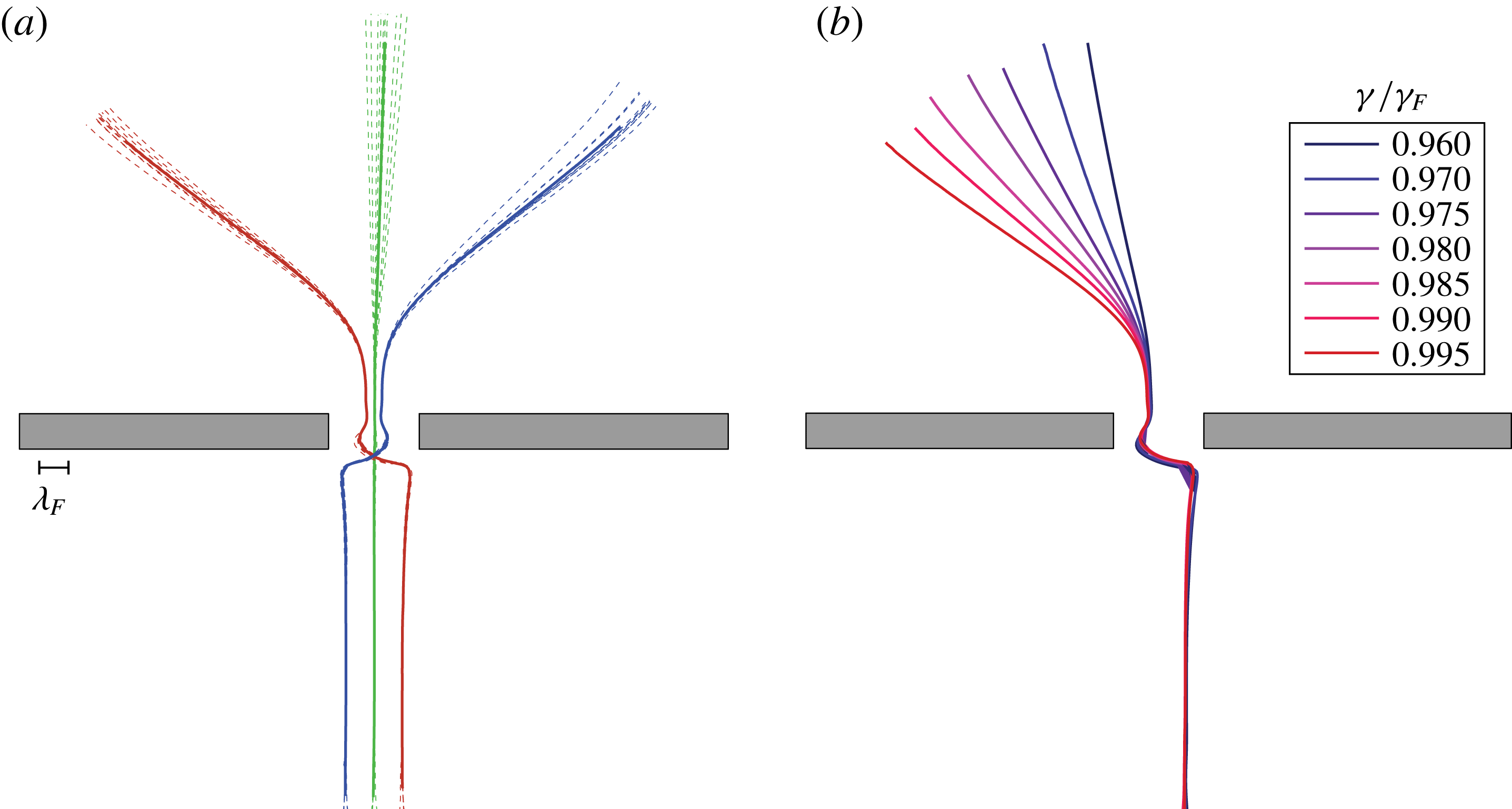
In figure 11(a), we examine the reproducibility of trajectories and their dependence on memory. At the onset of the chaotic regime,
 $\unicode[STIX]{x1D6FE}/\unicode[STIX]{x1D6FE}_{F}=0.990$
, for fixed impact parameter, deflection angles vary only by a few degrees (see figure 4
e). This small variation allows us to define average trajectories (figure 11
a) and to study their dependence on memory,
 $\unicode[STIX]{x1D6FE}/\unicode[STIX]{x1D6FE}_{F}$
(see figure 11
b). For a fixed off-centre impact parameter, the average deflection angle increases monotonically with memory, reaching
 $|\unicode[STIX]{x1D6FC}|\sim 60^{\circ }$
at
 $\unicode[STIX]{x1D6FE}/\unicode[STIX]{x1D6FE}_{F}=0.995$
(figure 11
b).



