Introduction
The concept of planar circuit analysis was first introduced by Ref. [Reference Okoshi1–Reference Okoshi3], as a method for analyzing two-dimensional microwave integrated circuits. In general, for an N-port planar circuit, when port locations are specified, the impedance matrix of a planar circuit can be obtained using three methods; (a) Green's function for planar circuits with regular geometrical shapes [Reference Okoshi and Miyoshi4], (b) numerical techniques such as the contour integral method for completely arbitrary shapes [Reference Patel and Triverio5–Reference Omar, Chow and Stubbs7], and (c) segmentation and desegmentation methods, or more generally known as the planar circuit method (PCM), for analysis of composites of regular and arbitrary shapes [Reference Sharma and Gupta8–Reference Abaei and Mehrshahi11]. The latter is adopted in this work. Reports show that a variety of devices have been analyzed using PCM, including rectangular waveguides [Reference Encinar, Wan and Mosig12], substrate integrated waveguides (SIW) [Reference Kishihara, Yamane and Ohta13], and antennas [Reference Lee, Ooi, Sambell, Korolkiewicz and Scott14, Reference Rogier, De Zutter, De Mulder and Vandewege15]. However, to the best of authors' knowledge, no report has been published to illustrate the use of PCM in the analysis of planar coupled lines and thus, synthesis of multi-section coupled-line filters. To this end, a new simple and very reliable tool is proposed based on the analysis provided in the present paper. The tool relies on the development of the so-called modified-PCM (MPCM) in an attempt to synthesize N-port coupled lines using desegmentation method, in combination with transmission line method (TLM), and then extending this to multi-section coupled-lines using segmentation method [Reference Abaei, Mehrshahi and Sadreazami16]. Thus, as shall be explained in details, the approach is fundamentally different than those solely based on TLM (e.g. [Reference Kogure, Kogure and Rautio17]), or even PCM. Appropriate relations are also developed and given in the section “Coupled-line analysis using MPCM and TLM.” As is demonstrated, the tool owes its simplicity and fast rendering to adoption TL analysis within its core module, making it super flexible in transforming from single-section to multi-section coupled-lines and filters. Validity and accuracy of the proposed tool are examined and confirmed against commercially-available simulators such as high-frequency structure simulator (HFSS) in the section “Multi-section coupled-line filter synthesis using MPCM-TLM,” for 3rd, 5th, and 7th order coupled-line bandpass filters with appropriate simulation and measurement results. Finally, conclusions are drawn in the section “Conclusion."
Coupled-line analysis using MPCM and TLM
Choosing the most suitable method for analyzing, planar circuits mainly depend on the level of complexity of computations involved. For example, Green's function is used for simple geometries such as rectangle, triangle or circle, to give the voltage at any point on the planar circuit for a unit current source excitation elsewhere [Reference Itoh18]. Here, MPCM is used in the form of segmentation and desegmentation techniques (refer to Appendix A) to form and analyze a pair of coupled lines. Thus, desegmentation is used for the design (extraction) of coupled line patches, and segmentation is then used to connect these coupled lines together to create the coupled-line filter design as shall be seen.
Coupled-line analysis using MPCM
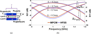
The idea presented here is that a coupled-line structure can be formed, assuming two concentric rectangles γ and β, if the inner rectangle (β-circuit) is extruded longitudinally from either side of the outer one (γ-circuit), resulting into two patches namely α, as seen in Fig. 12(b). Therefore, by adjusting port localization, and thereby modifying the PCM, coupled lines can be created and analyzed using desegmentation of two rectangular patches γ and β, as depicted in Fig. 1(a); where Pa represents input and output ports on α. Similarly, Q and R denote common (red) ports on the interface between α and β, and Pb (green) ports in the middle of β, respectively. The resulting coupled line is designed on Rogers RO4003 substrate with ɛr = 3.55 and thickness h = 1.6 mm, and analyzed using the MPCM. The results are plotted against those obtained from the commercially available full-wave software, HFSS, as illustrated in Fig. 1(b). As seen, a very good agreement is evident between the results, for different spacing values (S 1 and S 2) (see Fig. 1(b)); hence validating the MPCM technique to analyze coupled-line structures. Referring to Fig. 1(b), note that the emphasis here has not been on whether or not a good coupled line has been designed. In other words, a coupled line with not-so-good S-parameters response (particularly S 11) has been designed intentionally, so a meaningful comparison can be made, and that a better contrast (higher resolution) can be made between the two responses.
(a) Illustration of coupled lines made by desegmentation of two planar rectangular patches, for input (IP) and output (OP) ports; W (line width of rectangular patch) = 1.5 mm, L (line length of rectangular patch) = 48 mm; and (b) S-parameters plot of the coupled-line structure obtained by MPCM and HFSS for two different spacing values (S 1 = 0.2 mm and S 2 = 0.7 mm) between adjacent planar rectangular patches.

Multi-section coupled-line structure can be designed by connecting coupled-line pairs using the segmentation process (see Fig. 2). This requires calculating the impedance matrix for every coupled line separately using desegmentation relation (A6), and then linking up rectangles using segmentation relation (A4). Evidently, design of multi-section coupled-lines in commercially-available software (be it ADS, HFSS, CST, etc.) is an iterative process and involves complex, processor-intensive and time-consuming optimizations. In this paper, a new approach is presented, which is manifested in the form of an open-source tool, that significantly reduces such complexity. As shall be explained in the following section, the proposed tool is based on simultaneously utilizing the MPCM and impedance calculations of single coupled-line section. Relying on simple, fast, and accurate lumped-element equivalent circuit analysis, equivalent circuit lumped element values are calculated and optimum associated coupled-line geometric parameters are generated, producing the final design layout very quickly.
(a) Equivalent bi-section planar circuit model (with N ports), and (b) layout of the cascaded multi-conductor coupled-line structure.

Extracting equivalent circuit values using TLM
Figure 3(a) depicts the structure of a simple two-conductor coupled-line with line width, W, spacing between two lines, S, length of coupled lines, l. Equivalent circuit model of this coupled-line for an infinitesimal line section Δx is shown in Fig. 3(b); where L, C, R and G are per-unit-length inductance, capacitance, resistance and conductances, respectively. Also, Lm and Cm represent mutual coupling inductance and capacitance, respectively.
(a) Layout and (b) equivalent circuit model of a two-conductor coupled-line.

Referring to Fig. 3(b), the idea is that using the relations obtained from MPCM (i.e. (A5) and (A6)) and those obtained from TLM, a set of simultaneous equations can be obtained based on Z parameters, from which lumped-element parameters L, C, Lm, and Cm can be calculated as shall be seen.
Assuming a lossless line, impedance (Z) and admittance (Y) matrices of the coupled line of Fig. 3(a) can be given as [Reference Schutt-Aine and Mittra19]:


where ω is the angular frequency.
Applying Kirchhoff's voltage and current laws (KVL and KCL) to the equivalent circuit of Fig. 3(b), one hasdV/dx = −ZI anddI/dx = −YV, which (after differentiation of the latter and substitution into the former) gives d 2V/dx 2 = ZYV(x denotes the infinitesimal TL section along the direction of propagation). Substituting V in d 2V/dx 2 = ZYVby its exponential form V ∝ e γx gives γ 2UV = ZYV, where γ is the propagation constant and U is the unit matrix.
Substituting Z and Y from (1) and (2) into γ 2UV = ZYVand solving it gives:

Given γ = jβ, phase constant β can be obtained from (3) as:


For the coupled line, the Telegrapher's Equations can result in input and output voltages and currents (V 1, I 1 and V 2, I 2) of [Reference Schutt-Aine and Mittra19]:

Given dV/dx = −ZI and substituting Z by (1), the current matrix can be obtained as:

Now that V and I matrices are found (from (5) and (6)), considering the boundary condition and symmetry of impedance matrix by substituting β in voltage and current relations, four main elements of impedance matrices Z of a lossless coupled line can be found. As such one can obtain Z 11 matrix at point x = −l by dividing (5) by (6):

which simplifies to:

where β 1 and β 2 have already been defined in terms of L and C parameters in (4).
Similarly, Z 12 is obtained as:

which simplifies to:

And Z 13 is obtained as:

which simplifies to:

And finally, Z 14 is obtained as:

which simplifies to:

Therefore, the Z matrix of the coupled line with four ports under the symmetry, reciprocity, and unitary conditions can be written as:

The impedance matrix of (11) can be determined if the equivalent circuit parameters L, C, Lm, and Cm are known. However, since these parameters are all unknown for start, one has to use four simultaneous equations of (7)–(10). Interestingly, left-hand-side (LHS) of (7)–(10) correspond to the first element of Zα given in (A6) obtained from the MPCM analysis for four external ports (pa) associated to ports 1 to 4 of the coupled line of Fig. 3(a); that is:

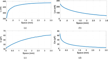
These elements are then substituted in LHS of relations (7)–(10) to solve four simultaneous equations (using the Gradient method) and to extract the four unknowns L, C, Lm, and Cm. In other words, Z 11, Z 21, Z 31, and Z 41 which are obtained from MPCM analysis are substituted in (7)–(10) obtained from equivalent circuit analysis; and solved to give values of L, C, Lm, and Cm. These values are then tabulated in a look-up table and plotted in Fig. 5.
Note that, considering that modal analysis has been used in the parallel-coupled lines, effectively frequency dispersion has been considered in calculations. Moreover, referring to (4), the terms $e^{{-}j\beta _1x}$ and $e^{{-}j\beta _2x}$
 indicate two different propagation constants in the coupled line, which is indeed a manifestation of frequency dispersion. Moreover, since the above relations are deduced from Maxwell's equations, which itself takes frequency dispersion into account, then the proposed approach also takes account of frequency dispersion. A fact that is approved by almost identical results obtained from both full-wave simulator (HFSS) and the proposed technique, as shall be seen.
To verify the validity of the proposed method, the coupled-line designed using MPCM (seen in Fig. 1(a)) is assumed on Rogers RO4003 substrate (h = 0.25 mm, ɛr = 3.55, TanD = 0.0027), with line width W = 1.5, spacing S = 0.8, and length l = 48 (all in mm). Utilizing (A6), and (7)–(10), the lumped element values associated with the specified geometries are determined to be, L = 432.55nH, C = 42.86pF, Lm = 125.37nH, and Cm = 12.15pF. As such, relevant S-parameters are produced by simple Z-to-S conversion. The same geometry is also analyzed in the full-wave simulator ANSYS HFSS in order to compare the results with the presented method.
As depicted in Fig. 4, a very good match is evident between results obtained from HFSS and the proposed method; confirming the validity and accuracy of the proposed technique.
S-parameters of the analyzed coupled-line obtained from HFSS, MPCM and proposed tool.

Regardless of the technique used, analysis of multi-section coupled-line structures becomes very complicated, be it using PCM, MPCM or well-known methods such as Moments or FEM; due to the large number of analytical ports involved (in MPCM) (see Fig. 2(a)), meshing, and iteration frequency (in HFSS). However, the beauty of the proposed approach is that it is inherently simple, as the MPCM method is used once only at the beginning of the analysis, and that the rest of analysis relies on solving straight-forward simple TL equations; thus, offering the ability to rapidly generate the optimal layout. Therefore, the presented technique is extended to offer a simplified procedure for the design of multi-section coupled-lines; where the analysis of the overall structure would involve analysis of individual coupled-line sections from (11).
In order to provide a comprehensive dataset for the developed tool, calculations have been carried out for a range of different values of S (assuming fixed TL widths), for which relevant L, C, Lm, and Cm have been extracted from the combination of MPCM and equivalent circuit method (i.e. equations (7)–(10)) and recorded in the form of a look-up table. Thus, for a coupled line with fixed line widths, only the spacing S must be specified, according to which L, C, Lm, and Cm are extracted immediately. Figure 5 is a graphical illustration of electrical versus physical parameters of the coupled-line analyzed earlier in this paper, plotted from the look-up table. Note that limited data have been shown in the figure for illustration purposes only.
Plot of change of L, Lm, C, and Cm change of S at 0.6–1.6 GHz for W = 1.5 mm, L = 48 mm on Rogers RO4003 with ɛr = 3.55, and h = 0.25 mm.

Also, note how the extracted coupling parameters in Fig. 5 are plotted in terms of line spacing, and that loss is independent of the spacing, and so, excluding loss does not reduce the generality of the problem.
Evidently, such information can be very useful in that for any desired spacing, associated lumped-element values (L, C, Lm, and Cm) can be extracted immediately, and vice versa. The data become particularly useful if more than one pair of coupled-line section (a multi-section coupled-line) is present; since the same procedure can be applied to the other pairs of coupled-line structure too (assuming minimum or no mutual coupling between pairs of coupled-line). These extracted lumped-element values can be substituted in (7)–(10), yielding in Z matrix (relation (11)) for each coupled-line section. The Z matrices shall be converted into ABCD matrices, then multiplied, to result in the overall Z matrix (and eventually the S-parameters) of the multi-section coupled-line.
Multi-section coupled-line filter synthesis using MPCM-TLM
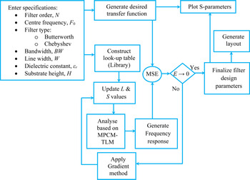
Here, multi-section coupled-line filters are designed based on the analysis provided so far. The flowchart of Fig. 6 illustrates the proposed design procedure graphically in order to simplify the design process.
Design procedure for the proposed multi-section coupled-line filter, MSE: mean squared error.

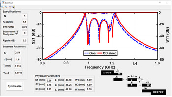
As is seen, one should enter filter specifications including desired frequency response (filter type, filter order, N, center frequency F 0, bandwidth, BW) and substrate parameters (TL widths W, substrate height H, and relative dielectric constant, ɛr). A customized look-up table (or so-called library) is constructed accordingly using data of Fig. 5, from which optimum TL length L (λ/4 at F 0) and spacing S are chosen, to generate a frequency response based on the proposed method. The generated response is then compared to the desired transfer function, producing an error difference, E. If E → 0 is satisfied, final physical parameters are produced based on which filter layout is generated and S-parameters are plotted. However, if E → 0 is not satisfied, optimization (the Gradient method) is applied in an iterative process to generate updated L and S values, producing closer-to-desired frequency responses until the condition is met [Reference Moradian and Oraizi20–Reference Pierre22]; eventually offering an optimal filter layout. Screenshot of the developed tool for 5th order coupled-line bandpass filter is illustrated in Fig. 7.
Screenshot of the developed tool for the case of 5th order coupled-line bandpass filter.

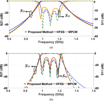
The final section of this paper takes a step further to validate the proposed technique, by designing 3rd, 5th, and 7th order multi-section coupled-line filters on different substrates, and compare the results against those obtained from HFSS and MPCM. Moreover, the 7th order coupled-line filter, which is designed using the proposed tool for direct broadcast satellite (DBS) applications, is fabricated. Figure 8 compares S-parameter results for (a) 3rd order and (b) 5th order coupled-line filters designed on Arlon AD255A (ɛr = 2.54, h = 1.6 mm, TanD = 0.0015), and Taconic TLT (ɛr = 2.54, h = 1.6 mm, TanD = 0.0006), respectively. Evidently, in both cases, the results obtained from the proposed method match very closely with those obtained from HFSS.
S-parameters of (a) 3rd order coupled-line filter (W 1 = 1.5 ،W 2 = 1.9، L 1 = L 2 = 48, S 1 = 0.4 ،S 2 = 0.8), and (b) 5th order coupled-line filter (W 1 = 1.6, W 2 = 2, W 3 = 2, L 1 = L 2 = L 3 = 48, S 1 = 0.4, S 2 = 0.8, S 3 = 1.25), designed with HFSS, MPCM, and proposed method (MPCM-TLM) (all dimensions in mm).

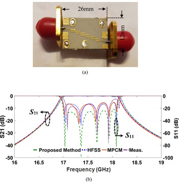
Furthermore, the 7th order bandpass filter is designed based on the proposed technique and fabricated on Rogers RO4003 with ɛr = 3.55, h = 0.25 mm, TanD = 0.0027 (photograph seen in Fig. 9(a)). Measurement results of this filter are compared against those obtained from MPCM, HFSS, and the proposed tool, as depicted in Fig. 9(b). It is clear evidence that the results are all in very good agreement and thus, it is a solid validation of the functioning and accuracy proposed approach.
(a) Photograph of the 7th order fabricated filter, and (b) its S-Parameter response; (W 1 = 0.17, W 2 = 0.2, W 3 = 0.2, W 4 = 0.2, L 1 = 2.58, L 2 = L 3 = L 4 = 2.54, S 1 = 0.12, S 2 = 0.3, S 3 = 0.32, S 4 = 0.4) (all in mm).

To complete the comprehensive analysis presented in this paper, analysis run times for single coupled-line, and 3rd, 5th, and 7th order bandpass filters are recorded for MPCM and HFSS, and presented in Table 1. Additionally, overall synthesis run time (inclusive of optimization time) of the 7th order bandpass filter is included in the table for comparison. Evidently, for exactly the same initial simulation set-up (i.e. meshing, steps, etc.), simplicity of the proposed technique has manifested itself in minimum time consumption in the optimization process. This is a significant advantage particularly for the design of higher-order filters, where for instance in the case of 7th order filter, almost 99% time reduction in the analysis is recorded for obtaining almost the same results, which is a remarkable achievement.
Comparison of filter analysis (and synthesis) run times (all in seconds).

Therefore, it can be safely claimed that the technique proposed in this paper is by far superior to other popular techniques in terms of simplicity and run time (speed) in simulation and optimization, and so, can be used as a reliable alternative to those techniques. This is particularly thanks to the use of TL (hence, equivalent circuit model) analysis, enabling extendibility of such analysis to other multiport multi-section structures such as filters (or any device formed by coupled-lines); unlike in MPCM where complexity increases hugely as the number of ports increase, or in HFSS where increases in mesh number significantly adds to the complexity of structural analysis.
Conclusion
In this paper a new technique is presented for synthesis and design of coupled-lines and multi-conductor structures made of coupled-lines (such as coupled-line filters) which takes advantage of combined MPCM and TLM (referred to as MPCM-TLM), to offer a tool by far a simpler and faster optimization alternative to existing commercially available tools. It has been confirmed throughout the paper that for exactly the same initial simulation set-up (i.e. meshing, steps, etc.), almost identical results have been obtained from the proposed technique and the commercially-available tools such as HFSS. The simplicity of the proposed technique has manifested itself in minimum time consumption in the optimization process. This is a significant advantage particularly for the design of higher-order filters, where for instance in the 7th order bandpass filter, almost 99% time reduction in the analysis is recorded for obtaining almost the same results, which is a remarkable achievement in calculation efficiency. This is particularly thanks to the use of TL (hence equivalent circuit model) analysis, enabling extendibility of such analysis to other multiport multi-conductors such as wide range of filters (or any device formed by coupled-lines); unlike in PCM where complexity increases hugely as the number of ports increase, or in HFSS where increases in mesh number significantly add to the complexity of structural analysis.
Appendix
Planar circuit analysis using segmentation and desegmentation methods
In this section, segmentation and desegmentation techniques are briefly overviewed; to be used in the analysis of pair of coupled lines and eventually, design of coupled line filters in this paper. Figure 10 depicts an N-port planar circuit of arbitrary shape. Different ports can be defined along the periphery of this circuit with port widths of say wi and wj. The rest of the periphery is either open, shorted or terminated by an impedance wall [Reference Itoh18].
(a) A triplate-type planar circuit, (b) rectangular patch whose green's function is given in (2) [Reference Itoh18].

When port locations are specified, the impedance matrix Z ij characterizing the planar component can then be easily derived using the Green's function, in (A1).

where G(s|s 0) is the Green's function and p is constant (p = 1 for stripline and p = 2 for microstrip transmission line).
In Fig. 10(b), for a simple rectangular patch with the form of either γ or β, Green's function can be defined as:

where x and y are excitation points, and x 0 and y 0 are arbitrary observation points, μ: permeability, a: patch length, b: patch width, σ is a constant with σi = 1 (if i = 0), and σi = 2 (if i ≠ 0), and $k_x = {{m\pi } \over a}$ and $k_y = {{m\pi } \over b}$
 .
Segmentation method
The segmentation method, which was first introduced by [Reference Okoshi and Miyoshi4], is a planar procedure for network analysis of two-dimensional microwave circuits [Reference Okoshi3, Reference Okoshi and Miyoshi4]. It involves dividing a complex planar circuit into simple parts that have regular shapes whose general characteristic, impedance function and Green's function are known. Therefore, the impedance function and so the scattering matrix of the entire structure made of simple parts can be easily obtained. Such analysis requires assigning a number of ports to the overall structure and its constituent parts (see rectangular patches A and B in Fig. 11). The number of these ports depends on the common region interface [Reference Itoh18]. In Fig. 11, Pai and Pbi are input and output ports, and qi and ri (i = 1,2,3,…,n) are the number of intermediate ports, respectively.
Representation of an N-port planar circuit adopted in the segmentation analysis [Reference Itoh18].

In general, the relation between voltages and currents on different ports can be derived as:

where Zpp is impedance relation between all p ports (i.e. all Pai and Pbi ports), Zpq is impedance relation between all Pai and q ports, Zpr is impedance relation between all Pbi and r ports, and so on. Using the boundary condition Vq = Vr and iq = −ir in intermediate ports, Equation (A3) can be solved and the total impedance ZAB is obtained as [Reference Itoh18]:

Desegmentation method
Desegmentation method is used for irregular structures (e.g. shapes of Fig. 12), whose Green's function is not available, and so cannot be analyzed simply by the segmentation method.
Examples of desegmented planar circuits [Reference Itoh18].

In the case of the example of Fig. 12(a), impedance matrix of the trapezoid α can be obtained by adding a small triangle β to it, to form the larger triangle γ. So, by establishing the impedance matrices of triangles β and γ with known Green's functions, the impedance matrix of the trapezoid can be obtained. The same is true for Fig. 12(b), where the rectangular blue doughnut-shape α can be obtained when β and γ are known. Besides, the relation between Z-matrices of the three shapes is obtained when three sets of discrete ports are defined on the inner and outer interfaces, i.e. port Pa on the outside of γ, port Pb inside β, and intermediate ports q and r, on the border between α and β. The number of intermediate ports depends on the field changes along with the interface. Let the currents of the ports be Iq, Ir, Ipa, and Ipb, and the voltages equal to Vq, Vr, Vpa, and Vpb; and assuming that q = r, the boundary conditions are considered as Vq = Vr and Iq = −Ir. Thus, using (A1)–(A2), impedance matrices Zα, Zβ, and Zγ can be defined as [Reference Itoh18]:

Given the matrix elements β and γ, and using the PCM analysis, elements of the matrix can be obtained from (A6) [Reference Okoshi3].

Therefore, the impedance matrix Zα of the extracted shape (i.e. α) of Fig. 12(b) has been generated whose elements are port impedances.
 Elahe Faghand was born in Iran, in 1992. She received her B.S. from Shahed University and M.S. degree in electrical engineering from Shahid Beheshti University of Tehran, respectively, in 2015 and 2017. She is currently a Ph.D. student in the Department of Electrical Engineering at the Shahid Beheshti University.
 Dr. Shokrollah Karimian is an Assistant Professor in School of Electrical Engineering at Shahid Beheshti University. As a member of IEEE, with over 50 publications, he has made a valuable contribution to the RF and microwave/mm-wave community.
 Dr. Esfandiar Mehrshahi was born in Tehran, Iran 1964. He received his B.Sc. from Iran University of Science and Technology, Tehran, Iran, in 1987, and the M.Sc. and Ph.D. degrees from Sharif University of Technology, Tehran, Iran, in 1991 and 1998, respectively. Since 1990 he has been involved in several research and engineering projects at the Iran Telecommunications Research Centre (ITRC). He is currently an Associate Professor at Shahid Beheshti University, Tehran, Iran. His main areas of interest are non-linear simulation of microwave circuits and microwave oscillator's spectrum.
 Dr. Noushin Karimian received the Ph.D. degree in Electrical and Electronic Engineering from The University of Manchester, Manchester, UK, in 2014. Since then, she has been a Research Associate with University of Manchester on various international projects. She is a coauthor of more than 40 international conference and journal papers and has a registered patent. Her main research interests include electromagnetic sensors for NDT applications and digital signal processing. Dr. Karimian has been actively involved both as technical and organizational committee member of international conferences, and most recently the European Microwave Conference. She is a member of IEEE, IET, EuMA, BINDT, and IOP. She is currently acting as the Treasurer for the IEEE UK and Ireland Section, and a committee member of The University of Manchester IEEE Student Branch. She is also a committee member of the IEEE UK and Ireland Women in Engineering.