





1. Introduction
The propagation, reflection and refraction of acoustic waves in shear flows have been of great interest in engineering fields. Initially, investigations were triggered by an urgent need to understand and reduce noise that is induced by flows and machinery. To examine the properties of acoustics in free shear flows, a simple model was that of a plane vortex sheet (Jones & Morgan Reference Jones and Morgan1972; Crighton & Leppington Reference Crighton and Leppington1974). It facilitates the solution of the governing equations but is greatly simplified and neglects the effect of the shear layer thickness, the critical level (layer) and turning levels on acoustic wave propagation.
Another model for mimicking free shear flows is by a linear velocity profile. As early as 1958, Pridmore-Brown (Reference Pridmore-Brown1958) employed the normal-mode ansatz to derive an equation for acoustic waves in plane parallel shear flows based on the linearized Euler equations (LEE). This equation is a second-order ordinary differential equation that contains a function of the velocity profile and later known as the Pridmore-Brown equation (PBE). At that time, Pridmore-Brown (Reference Pridmore-Brown1958) gave only asymptotic solutions to the PBE for a linear velocity profile in the limit of small velocity gradients. It was not until more than a decade later that the solution to this equation was given for the first time by Goldstein & Rice (Reference Goldstein and Rice1973). The exact solution to the PBE for a linear velocity profile was given in different forms, i.e. parabolic cylinder functions (Goldstein & Rice Reference Goldstein and Rice1973), confluent hypergeometric functions (Jones Reference Jones1977) and a Fuchs–Frobenius series (Campos Reference Campos1999), to investigate the propagation of acoustic waves.
Meanwhile, a more realistic nonlinear velocity profile for mimicking a free shear layer, the hyperbolic-tangent velocity profile, was investigated by Michalke (Reference Michalke1965), Blumen, Drazin & Billings (Reference Blumen, Drazin and Billings1975), Drazin & Reid (Reference Drazin and Reid1979) and Michalke (Reference Michalke1984), with the main aim to investigate the stability of this profile. The Fuchs–Frobenius series solution to the PBE for this profile was given by Campos & Kobayashi (Reference Campos and Kobayashi2000), who studied the scattering effect of free shear flows on acoustic waves. Both the linear and hyperbolic-tangent profiles have been very successful in modelling the shear layers formed in different jet regions behind modern aircraft engines. For example, in a coaxial jet exhaust of a typical turbofan (Royce-Rolls 2015), the core region is approximated by a linear profile (Hau Reference Hau2017), and the mixing region is mimicked by a hyperbolic-tangent profile (Perrault-Joncas & Maslowe Reference Perrault-Joncas and Maslowe2008; Gloor, Obrist & Kleiser Reference Gloor, Obrist and Kleiser2013).
In addition to free shear flows, the propagation of acoustic waves in boundary layer flows is of increasing interest. Initially, the boundary layer was modelled by a simple linear profile extended by a constant velocity to meet a finite value in the free stream. However, this approach inevitably introduces an artificial kink between the linear and constant parts of the velocity profile, which in turn leads to non-physical reflections or refractions. Therefore, for boundary layer flows, a nonlinear smooth profile is physically more sound compared to linear ones. For this, an exponential velocity profile was introduced by Campos & Serrão (Reference Campos and Serrão1998), as it allows for a smooth transition between the boundary layer and the free-stream flow, which is much closer to physical reality. The same model was also suggested by Oberlack (Reference Oberlack2001) for a turbulent boundary layer flow using symmetry methods. Using turbulent boundary layer data at a very high Reynolds number from the experiments of Saddoughi & Veeravalli (Reference Saddoughi and Veeravalli1994), he concluded that the largest part of a turbulent boundary layer, i.e. the deficit region, is covered by an exponential profile. The conclusion was later validated by the experiments by Lindgren, Österlund & Johansson (Reference Lindgren, Österlund and Johansson2004).
The propagation of acoustic waves within boundary layer flows was investigated by Campos & Serrão (Reference Campos and Serrão1998), who gave a Fuchs–Frobenius series solution to the PBE for an exponential velocity profile. Of particular concern is the series solution near the critical layer, which contains a logarithmic term. Nonetheless, in the analysis of leading orders, they proved that the amplitude of the pressure perturbation near the critical layer tends to be constant rather than an infinite value. By studying the amplitude of acoustic waves, they noticed an attenuation of the wave amplitude adjacent to the critical layer. Recently, Zhang & Oberlack (Reference Zhang and Oberlack2021) gave an exact solution to the PBE for an exponential velocity profile in terms of the confluent Heun function (CHF) (Ronveaux & Arscott Reference Ronveaux and Arscott1995). Based on this, they investigated the temporal stability of exponential boundary layer flows and succeeded in giving unstable acoustic modes and the mechanism of the instability.
In addition to free shear flows, the PBE is also frequently applied to the study of acoustic stability and sound propagation in wall-bounded flows, e.g. duct flows. In a recent study, Rienstra (Reference Rienstra2020) constructed numerical solutions for acoustic modes in two- and three-dimensional lined ducts by the Galerkin projection-based spectral method and gave theoretical solutions for low and high frequencies by the asymptotic and WKB (Wentzel–Kramers–Brillouin) methods.
Links concerning shear layer instabilities and acoustic waves were first proposed in Gill (Reference Gill1965). In his study of shear layers separated by a vortex sheet, he argued that incident waves at certain resonant frequencies enhance instabilities. Based on this, Cohn (Reference Cohn1983), Payne & Cohn (Reference Payne and Cohn1985) and Zaninetti (Reference Zaninetti1986, Reference Zaninetti1987) gave detailed investigations of ‘reflection modes’ and temporal instability. Subsequently, Tam & Hu (Reference Tam and Hu1989a,Reference Tam and Hub) extended their studies to spatial instability in finite-thickness shear layers as well as mixing layers inside a rectangular channel, in which supersonic instability waves generated by continuous reflections were obtained. The links between instabilities and acoustic waves in previous work provided guidance for the current paper.
A unique phenomenon that arises in the acoustics of shear flows, and on which we will presently focus, is the over-reflection of waves, i.e. reflected amplitudes are greater than the amplitudes of the incoming waves. This phenomenon is validated to exist in many different shear systems (see e.g. Lindzen Reference Lindzen1988).
The phenomenon of over-reflection was first discovered simultaneously and independently by Ribner (Reference Ribner1957) and Miles (Reference Miles1957) in the study of plane acoustic waves that impinge onto a moving medium, and in the study of plane acoustic waves that propagate in two moving media separated by a vortex sheet, respectively. After this, studies on over-reflection were mainly focused on geophysical fluid dynamics (GFD), i.e. typically gravity waves and Rossby waves. The over-reflection of internal gravity waves in stratified shear flows was discovered by Jones (Reference Jones1968), who extended the research of Booker & Bretherton (Reference Booker and Bretherton1967) to Richardson numbers smaller than  $1/4$, thereby proposing that these waves were able to extract energy and momentum from the base flow and, in turn, lead to over-reflections.
Following this, Breeding (Reference Breeding1971) explored numerically nonlinear effects of the critical layer to internal gravity waves that produce over-reflections predicted from the linear theory. Analytical work on internal gravity waves was also done by Eltayeb & McKenzie (Reference Eltayeb and McKenzie1975), in which they proved Jones’ inference that the over-reflection can arise because incident waves indeed extract energy from shear flows. Analogous to the over-reflection mechanisms of gravity waves, the over-reflection of Rossby waves exists when they propagate across a jet flow. In Lindzen & Tung (Reference Lindzen and Tung1978) and Yamada & Okamura (Reference Yamada and Okamura1984), the necessary and sufficient conditions for the over-reflection of Rossby waves were derived.
The link between the over-reflection and the instability of shear flows has been extensively explored by Lindzen and coworkers, though focusing on the over-reflection of internal gravity waves and shear instabilities of stratified flows (Lindzen & Barker Reference Lindzen and Barker1985; Rosenthal & Lindzen Reference Rosenthal and Lindzen1983a,Reference Rosenthal and Lindzenb), over-reflection of Rossby waves and barotropic instabilities (Lindzen & Tung Reference Lindzen and Tung1978), over-reflection of Rossby waves and baroclinic instabilities (Lindzen, Farrell & Tung Reference Lindzen, Farrell and Tung1980) and over-reflection of Rossby waves and instabilities of viscous Poiseuille flows (Lindzen & Rambaldi Reference Lindzen and Rambaldi1986). In Lindzen (Reference Lindzen1988), the growth rate of unstable modes is estimated by the over-reflection coefficient, thereby successfully linking over-reflection and unstable modes. Furthermore, he inferred a mechanism of instability triggered by over-reflections and concluded that the instability of shear flows is caused by a combined process of over-reflection and the ‘Orr mechanism’ (Boyd Reference Boyd1983), which describes a transient growth process inducing instability. In Lindzen's theory, the over-reflection of waves acts like a source term, which provides a constant impetus for the ‘Orr mechanism’ and thus the transfer and transformation of energy from the base flow to the perturbation. An exhaustive description of this mechanism can be found in Harnik & Heifetz (Reference Harnik and Heifetz2007) from the Rossby wave perspective.
Lindzen's theory is confirmed in many areas. However, there are also researchers who do not support his finding and have been opposed to the conclusions. Among them, Takehiro & Hayashi (Reference Takehiro and Hayashi1992) suggested that the ‘Orr mechanism’ does not apply to the instability and over-reflection of shallow-water waves. They proposed an alternative theory that is based on momentum conservation of reflected and transmitted waves to reveal the mechanism by which over-reflection phenomena produce instabilities. This theory well explains the instability in linear shallow-water shear flows investigated by Satomura (Reference Satomura1981a,Reference Satomurab). A theoretical study was followed by Knessl & Keller (Reference Knessl and Keller1995) and their results were well matched to the numerical results in Takehiro & Hayashi (Reference Takehiro and Hayashi1992). In Balmforth (Reference Balmforth1999), he extended further the study in shallow-water flows to viscous and nonlinear regimes. It should be emphasized that the shallow-water wave equation is found to be the same form as the PBE employed in this paper. However, the analogous phenomenon of acoustic waves in an exponential boundary layer flow has not been investigated.
This gap triggered our interest. Applying the exact solution in Zhang & Oberlack (Reference Zhang and Oberlack2021) to the PBE for an exponential velocity profile, it is straightforward to obtain an explicit expression for the reflection coefficient of acoustic waves. Note that the approach to establishing a link between the over-reflection and instability in the present study differs from most previous work in GFD. Their focus was on how the over-reflection, an acoustic behaviour, triggers instability. In contrast, from an acoustic perspective, we are concerned about how over-reflections are influenced by unstable modes and how they behave.
Another very special over-reflection phenomenon is the so-called hyper-reflection, which is, however, less well studied. This phenomenon describes an over-reflection that is infinitely strong. Physically, this means that the reflected waves can exist without the triggering incident waves, i.e. they are spontaneously emitted by a homogeneous flow. In some publications, resonant over-reflection is also known as hyper-reflection. The earliest description of this special over-reflection originated in the study of Helmholtz instabilities of acoustic-gravity waves at a plane vortex sheet led by McKenzie (Reference McKenzie1972). In the study of Helmholtz instabilities of vertical stratified flows, Lindzen (Reference Lindzen1974) observed this phenomenon for internal gravity waves. In addition, resonant over-reflection was also found in two classical models of GFD. Resonantly over-reflected Rossby waves were found to exist in jets on the  $\beta$-plane model (Maslowe Reference Maslowe1991). More recently, Benilov & Lapin (Reference Benilov and Lapin2012) found that resonant over-reflection also occurs in internal gravity waves within rotating shallow water on the
 $f$-plane model.
A similar phenomenon has also been observed in the present study of the acoustic over-reflection in boundary layer flows. When the frequency of an incident acoustic wave is close to the resonant frequency, which is defined in the current work as the real part of the eigenvalues  $\omega _r$ of unstable modes, it is shown that there is an unusual but finite enhancement of the over-reflection. This phenomenon is defined by us as the resonant over-reflection. Note that, to the authors’ knowledge, both the terminologies ‘resonant over-reflection’ and ‘hyper-reflection’ are not well defined as well as distinguished in the GFD and the acoustics communities. In view of this situation, we give them clear definitions in the context of our study; for details see § 2.4.
The paper is structured as follows. In § 2, the basic model equations and a number of concepts in boundary layer acoustics are established. The exact solution to the PBE for an exponential velocity profile is given in terms of the CHFs. To describe the incident acoustic wave, the concept of incident angle  $\phi$ is introduced, and a relationship between the incident angle and frequency is established. According to the form of propagation of acoustic waves in the free stream, two types of waves are distinguished. In addition, critical angles of incidence for the existence of the critical layer are given. The above introduced physical quantities specify the computational domain for the over-reflection. Based on the exact solution to the PBE, the reflection coefficient
 $R$ is derived and explicitly expressed by the CHF. In the last part of § 2, we give a proof that, in the case of the existence of a critical layer,
 $|R|>1$ always holds. We further link over-reflection to a jump of a key quantity at the critical layer and show how this jump causes over-reflection.
In § 3, we display the reflection coefficient as a function of the wavenumber  $\alpha$, the Mach number
 $M$ and the incident angle
 $\phi$. Over-reflection of acoustic waves has been found to exist in boundary layer flows, which is closely related to the critical layer. The phenomenon of resonant over-reflection is observed and its close relation with unstable modes is interpreted. Eigenfunctions of acoustic waves are then displayed, and thereby three patterns of propagation of acoustic waves in boundary layer flows are identified. In § 4, we state the main conclusions of our study. Parts of the analysis and numerics in the present paper were aided by Maple (Maplesoft 2019) and MATLAB 2019a (Mathworks 2019).
2. Boundary layer acoustics
2.1. Governing equations
We consider an inviscid compressible flow without heat conduction, modelled by the Euler equations
 $$\begin{gather} \frac{{\rm D}\rho}{{\rm D}t} ={-}\rho\boldsymbol{\nabla}\boldsymbol{\cdot}\boldsymbol{v}, \end{gather}$$
 $$\begin{gather}\rho\frac{{\rm D}\boldsymbol{v}}{{\rm D}t}={-}\boldsymbol{\nabla}p, \end{gather}$$
 $$\begin{gather}\frac{{\rm D}s}{{\rm D}t}=0, \end{gather}$$
where  $\rho$ is density,
 $\boldsymbol {v}$ is the velocity vector,
 $p$ is pressure and
 $s$ is entropy. For linear acoustics, we suppose the variables
 $\rho$,
 $\boldsymbol {v}$ and
 $p$ to be composed of the base flow quantities
 $\rho _0$,
 $\boldsymbol {v}_0$ and
 $p_0$, and small unsteady perturbations
 $\rho '$,
 $\boldsymbol {v'}$ and
 $p'$, i.e.
 \begin{equation} (\rho, \boldsymbol{v}, p) =(\rho_0+\rho', \boldsymbol{v}_0+\boldsymbol{v}', p_0+ p'), \end{equation}
where the perturbations are functions of  $x$,
 $y$ and
 $t$. Then, we substitute (2.2) into equations (2.1a) and (2.1b), and neglect nonlinear terms.
To obtain a closed linearized equation system, we consider a homentropic (homogeneous and isentropic) and unidirectional flow, i.e.  $s_0={\rm const.}$ and
 $p_0={\rm const.}$, which indicates by the equation of state
 $\rho (p_0, s_0)$ that under a perfect gas assumption the density is a constant, i.e.
 $\rho _0={\rm const.}$ (Campos Reference Campos2007). A Taylor series expansion of the pressure about the reference thermodynamic state denoted by the subscript
 $0$ (neglecting higher-order derivatives) gives
 \begin{equation} p = p_0+p' = p(\rho_0+\rho',s_0) \approx p(\rho_0,s_0)+\left[\frac{\partial p} {\partial\rho}(\rho,s_0)\right]\rho' = p_0+c^2\rho', \end{equation}
where  $c=\sqrt {(\partial p/\partial \rho )}$ is the speed of sound. In this way, we omit the entropy equation (2.1c) and apply the linearized relation for the speed of sound to close the LEE system, which reads
 $$\begin{gather} \frac{\partial \rho'}{\partial t} +\boldsymbol{v}_0\boldsymbol{\cdot}\boldsymbol{\nabla}\rho' +\rho_0\boldsymbol{\nabla}\boldsymbol{\cdot}\boldsymbol{v}' +\boldsymbol{v}'\boldsymbol{\cdot}\boldsymbol{\nabla}\rho_0 +\rho'\boldsymbol{\nabla}\boldsymbol{\cdot}\boldsymbol{v}_0 = 0, \end{gather}$$
 $$\begin{gather}\rho_0\left(\frac{\partial \boldsymbol{v'}}{\partial t} +\boldsymbol{v}_0\boldsymbol{\cdot}\boldsymbol{\nabla}\boldsymbol{v'}\right) +\boldsymbol{\nabla}p' +\rho_0\boldsymbol{v'}\boldsymbol{\cdot}\boldsymbol{\nabla}\boldsymbol{v}_0 +\rho'\boldsymbol{v}_0\boldsymbol{\cdot}\boldsymbol{\nabla}\boldsymbol{v}_0 = 0, \end{gather}$$
 $$\begin{gather}p'= c^2\rho'. \end{gather}$$
For the proposed unidirectional two-dimensional parallel shear flow, an exponential velocity profile is employed to mimic a boundary layer flow, i.e.
 $$\begin{gather} u_0(y)=U_{\infty}(1-{\rm e}^{-{y}/{\delta}}), \end{gather}$$
 $$\begin{gather}v_0(y)=0, \end{gather}$$
where  $u_0$ and
 $v_0$ stand for the mean flow velocity in the
 $x$- and
 $y$-directions, respectively,
 $U_\infty$ is the free-stream velocity and
 $\delta$ is the shear layer thickness, which is a multiplier of the hydrodynamic boundary layer thickness. An intuitive illustration of the base flow is shown in figure 1. Definitions of the incident angle
 $\phi$, the propagation angle
 $\varTheta$ and the reflection coefficient
 $R$ in figure 1 are given in §§ 2.2 and 2.4.
Illustration of an exponential boundary layer flow. An incident acoustic wave from the free stream gives rise to a reflected wave with angle  $\varTheta$, characterized by the reflection coefficient
 $R$. The critical layer
 $y_c$ is marked by the dashed line. Further, a geometric relation of an acoustic wave with frequency
 $\tilde {\omega }$ in a medium at rest, between wavenumber vector
 $\tilde {\boldsymbol {k}}$ and streamwise wavenumber
 $\tilde {\alpha }$, is given by their angle
 $\phi$ (incident angle).

Inserting (2.5) into (2.4) and eliminating  $p'$, we get a system, which, non-dimensionalized by
 $U_\infty$,
 $\delta$ and
 $\rho _0$, reads
 $$\begin{gather} \frac{\partial{\rho}}{\partial {t}} +(1-{\rm e}^{-{y}})\frac{\partial{\rho}}{\partial{x}} +\left(\frac{\partial{u}}{\partial{x}}+\frac{\partial{v}}{\partial{y}}\right) = 0, \end{gather}$$
 $$\begin{gather}\frac{\partial {u}}{\partial {t}} +(1-{\rm e}^{-{y}})\frac{\partial {u}}{\partial{x}} +{\rm e}^{-{y}}{v}+\frac{1}{M^2}\frac{\partial{\rho}}{\partial{x}}=0, \end{gather}$$
 $$\begin{gather}\frac{\partial {v}}{\partial {t}} +(1-{\rm e}^{-{y}})\frac{\partial {v}}{\partial{x}} +\frac{1}{M^2}\frac{\partial {\rho}}{\partial{y}}=0, \end{gather}$$
where  $M=U_{\infty }/c$ is the global or free-stream Mach number. For the sake of simplicity, we have dropped the primes in (2.6), but keep in mind that we analyse the perturbations, while
 $x$,
 $y$ and
 $t$ have been respectively normalized by
 $\delta$ and
 $\delta /U_\infty$.
It is worth noting that we have adopted a different dimensionless approach here than the traditional approach in the field of acoustics, i.e. using the free-stream velocity  $U_\infty$ rather than the speed of sound
 $c$ to non-dimensionalize. The current approach agrees with the dimensionless variables introduced for the stability analysis in Zhang & Oberlack (Reference Zhang and Oberlack2021). We kept these definitions as it makes it more convenient to establish links between stability theory and acoustics, which is one of the key topics of the present work. Clearly, the parameters and results obtained by different dimensionless approaches are interchangeable.
Considering a two-dimensional perturbation, a normal-mode approach for density and velocity perturbations is applied. Similar to the classical stability theory, which involves Fourier decomposition in  $x$ and
 $t$, we introduce
 \begin{equation} q(x,y,t) =\hat{q}(y){\rm e}^{{\rm i}(\alpha x-\omega t)}, \end{equation}
with  $q\in (u,v,\rho )$, where the quantities
 $\hat {u}(y)$,
 $\hat {v}(y)$ and
 $\hat {\rho }(y)$ represent the amplitudes of the perturbations,
 $\alpha$ denotes the dimensionless streamwise wavenumber and
 $\omega$ stands for the dimensionless frequency.
Substituting the normal-mode ansatz (2.7) into the system of partial differential equations (2.6) results in a system of ordinary differential equations:
 $$\begin{gather} \frac{{\rm d}\hat{v}}{{\rm d} y}+{\rm i}[-(\omega-\alpha+\alpha {\rm e}^{{-}y})\hat{\rho}+\alpha \hat{u}]=0, \end{gather}$$
 $$\begin{gather}{\rm e}^{{-}y}\hat{v}+{\rm i}\left[\frac{\alpha}{M^2}\hat{\rho} -(\omega-\alpha+\alpha {\rm e}^{{-}y})\hat{u}\right]=0, \end{gather}$$
 $$\begin{gather}\frac{1}{M^2}\frac{{\rm d}\hat{\rho}}{{\rm d}y}-{\rm i} (\omega-\alpha+\alpha {\rm e}^{{-}y})\hat{v}=0. \end{gather}$$
We rewrite equations (2.8) into an equivalent second-order differential equation with a single dependent variable  $\hat {\rho }$. For this we express
 $\hat {v}$ by
 ${\rm d}\hat {\rho }/{{\rm d} y}$ through (2.8c), substitute the result for
 $\hat {v}$ in (2.8b) and thereafter express
 $\hat {u}$ in terms of
 $\hat {\rho }$ and
 ${\rm d}\hat {\rho }/{{\rm d}y}$. Finally, we substitute these results for
 $\hat {u}$ and
 $\hat {v}$ into (2.8a) to get the second-order ordinary differential equation for
 $\hat {\rho }$:
 \begin{equation} \frac{{\rm d}^2\hat{\rho}}{{{\rm d} y}^2} +\frac{2\alpha {\rm e}^{{-}y}}{\omega-\alpha+\alpha {\rm e}^{{-}y}} \frac{{\rm d}\hat{\rho}}{{\rm d} y} +[M^2(\omega-\alpha+\alpha {\rm e}^{{-}y})^2-\alpha^2]\hat{\rho}=0, \end{equation}
known as the PBE (Pridmore-Brown Reference Pridmore-Brown1958).
If a solution  $\hat {\rho }$ to (2.9) is obtained,
 $\hat {u}$ and
 $\hat {v}$ can be expressed in terms of
 $\hat {\rho }$ as
 \begin{equation} \hat{u}={-}\frac{{\rm e}^{{-}y}}{M^2(\omega-\alpha+\alpha {\rm e}^{{-}y})^2} \frac{{\rm d}\hat{\rho}}{{\rm d} y} +\frac{\alpha}{M^2(\omega-\alpha+\alpha {\rm e}^{{-}y})}\hat{\rho} \end{equation}
and
 \begin{equation} \hat{v}=\frac{1}{{\rm i}M^2(\omega-\alpha+\alpha {\rm e}^{{-}y})} \frac{{\rm d}\hat{\rho}}{{\rm d} y}. \end{equation}
The PBE (2.9) not only constitutes an eigenvalue problem for modes to investigate stability problems, as was detailed in Zhang & Oberlack (Reference Zhang and Oberlack2021), but also describes acoustic wave propagation (non-resonant spectra) in boundary layer flows, which is the main topic of the present work.
In Zhang & Oberlack (Reference Zhang and Oberlack2021), an exact solution to (2.9) was derived in terms of the CHF denoted by  ${\mbox {Hc}}(p_*,\alpha _*,\gamma _*,\delta _*,\sigma _*;z)$, where
 $p_*,\ \alpha _*,\ \gamma _*,\ \delta _*,\ \sigma _*$ stand for five parameters and
 $z$ is the independent variable (see e.g. Ronveaux & Arscott Reference Ronveaux and Arscott1995). The solution reads
 \begin{align} \hat{\rho}(y) &= C_1 \exp({{\rm i} M\alpha {\rm e}^{{-}y}+\sqrt{\theta}\,y}) {\mbox{Hc}}\left(p_*,\alpha_*,\gamma_*,\delta_*,\sigma_*;\frac{\alpha {\rm e}^{{-}y}}{\alpha-\omega}\right)\nonumber\\ &\quad +C_2 \exp({{\rm i} M\alpha {\rm e}^{{-}y}-\sqrt{\theta}\,y}) {\mbox{Hc}}\left(\tilde{p}_*,\tilde{\alpha}_*,\tilde{\gamma}_*,\tilde{\delta}_*, \tilde{\sigma}_*;\frac{\alpha {\rm e}^{{-}y}}{\alpha-\omega}\right), \end{align}
where
 \begin{equation} \theta={-}M^2(\alpha-\omega)^2+\alpha^2 \end{equation}
and the parameters are defined as follows:
 \begin{gather} \left. \begin{gathered} p_*=\tfrac{1}{2}{{\rm i}M(\alpha-\omega)}, \quad \alpha_*={\rm i} M (\alpha-\omega)-\tfrac{1}{2}-\sqrt{\theta}, \quad \gamma_*=1-2\sqrt{\theta},\\ \delta_*={-}2, \quad \sigma_*={\rm i}M(\alpha-\omega)-2M^2(\alpha-\omega)^2 -2\sqrt{\theta}[{\rm i}M(\alpha-\omega)+1], \end{gathered} \right\} \end{gather}
 \begin{gather} \left. \begin{gathered} \tilde{p}_*=\tfrac{1}{2}{{\rm i}M(\alpha-\omega)}, \quad \tilde{\alpha}_* ={\rm i}M(\alpha-\omega)-\tfrac{1}{2}+\sqrt{\theta}, \quad \tilde{\gamma}_*=1+2\sqrt{\theta}, \\ \tilde{\delta}_*={-}2, \quad \tilde{\sigma}_*={\rm i}M(\alpha-\omega) -2M^2(\alpha-\omega)^2+2\sqrt{\theta}[{\rm i}M(\alpha-\omega)+1]. \end{gathered} \right\} \end{gather}
In the following pages, for the sake of brevity, we omit the parameters of the  $\mbox {Hc}$ function and express the
 $\mbox {Hc}$ function simply as
 $\mbox {Hc}(;z)$ and
 $\widetilde {\mbox {Hc}}(;z)$ with their respective parameters as in (2.14) and (2.15), and
 $z=\alpha \textrm {e}^{-y}/(\alpha -\omega )$. As, in this paper, we investigate boundary layer acoustics, only
 $\alpha \in \mathbb {R}$ and
 $\omega \in \mathbb {R}$ will be considered. Note that in stability problems one has
 $\omega \in \mathbb {C}$ for temporal instability or
 $\alpha \in \mathbb {C}$ for spatial instability.
2.2. Zone of silence
Assume that the incoming acoustic wave has unit amplitude and propagates at a constant speed of sound  $c$ from the free stream, which is characterized by the dimensional quantities of frequency
 $\tilde {\omega }$ and horizontal wavenumber
 $\tilde {\alpha }$. The incident angle
 $\phi$, being a ‘secondary’ parameter, is defined as
 $\phi \in [0^\circ, 90^\circ ]$, which is the angle between the incident wave and the
 $x$-direction shown in figure 1. Here, first, we intend to establish a relationship between the incident angle
 $\phi$ and the frequency
 $\tilde {\omega }$ in order to facilitate
 $\phi$ as the main parameter to visually describe the incident acoustic wave. Using
 $\phi$ instead of
 $\tilde {\omega }$ reduces one parameter in analysing the critical cases shown in figure 2.
Borders of the zone of silence  $\phi _{s_0}$ (thick blue solid line),
 $\phi _{s_1}$ (thick red solid line),
 $\phi _{s_2}$ (thick black solid line) in (2.24) and the critical value for the presence of the critical layer
 $\phi _c$ (black dashed line) in (2.26) as functions of the Mach number
 $M$. The grey region indicates the zone of silence. The vertically striped region is the propagation zone and the horizontally striped region represents the presence of the critical layer.

The horizontal wavenumber of an acoustic wave in a medium at rest is given by
 \begin{equation} \tilde{\alpha}=|\tilde{\boldsymbol{k}}|\cos(\phi)=\frac{\tilde{\omega}}{c}\cos(\phi). \end{equation}
In dimensionless form it gives
 \begin{equation} \omega=\frac{\alpha}{M\cos(\phi)}, \end{equation}
where a dimensionless wavenumber  $\alpha =\tilde {\alpha }\delta$ has been used; or alternatively the wavelength
 $\tilde {\lambda }$ may be employed,
 $\tilde {\alpha }=2{\rm \pi} /\tilde {\lambda }$, so that we have
 \begin{equation} \alpha=\frac{2{\rm \pi}\delta }{\tilde{\lambda}}, \end{equation}
which implies a ratio between the shear layer thickness and the wavelength of the perturbation. This ratio indicates the range of  $\alpha$ taken in § 3 from 0.1 to 10, implying that the thickness of the boundary layer varies from small to large relative to the wavelength scale.
Note that the incident angle  $\phi$ in (2.17), which is an angle between the wavenumber vector
 $\tilde {\boldsymbol {k}}$ and the streamwise direction, is strictly speaking for a medium at rest, i.e.
 $U_\infty =0$, and hence
 $\phi$ is only an ‘auxiliary’ parameter used as a replacement to implicitly express the frequency. It is not the true propagation angle of the acoustic wave in the free stream. The ‘true’ angle of the incident wave propagating towards the boundary layer in the free stream, due to the velocity of the free stream
 $U_{\infty }$, is determined by the wavenumber of the acoustic wave in the
 $y$-direction. This wavenumber is given by the solution to the PBE in the free stream.
In the free stream  $(y\to \infty )$, where any shear is absent, the PBE (2.9) simplifies to
 \begin{equation} \frac{{\rm d}^2\hat{\rho}}{{{\rm d} y}^2} +[M^2(\omega-\alpha)^2-\alpha^2]\hat{\rho}=0, \end{equation}
which has oscillatory (waveform) solutions when the term in (2.19) in square brackets is greater than zero, i.e.  $\theta =-M^2(\alpha -\omega )^2+\alpha ^2<0$. The same result can also be derived directly by setting
 $y\to \infty$ in the exact solution (2.12), where
 $\mbox {Hc}(;0)=1$ and
 $\widetilde {\mbox {Hc}}(;0)=1$, and the solution reads
 \begin{equation} \hat{\rho}(y)=C_1 {\rm e}^{\sqrt{\theta}y}+C_2 {\rm e}^{-\sqrt{\theta}y}, \end{equation}
where the principal value of  $\sqrt {\theta }$ is taken and the branch cut is along the negative real axis.
For  $\theta <0$, the wavenumber in the
 $y$-direction in the free stream reads
 \begin{equation} \beta=\sqrt{-\theta}, \end{equation}
where the principal value of the square root is taken. It follows that the two solutions in (2.20) stand for an outgoing wave  $(C_1 \textrm {e}^{\textrm {i}\beta y})$ and an incoming wave
 $(C_2 \textrm {e}^{-\textrm {i}\beta y})$, respectively, for
 $\theta <0$ and
 $\theta \in \mathbb {R}$. This can be intuitively observed by the shifts of the peaks and troughs of the waves in time by adding the time dependence in the normal mode (2.7).
It is important to note that this work is restricted to purely acoustic free-stream behavior, which means real wavenumbers  $\beta \in \mathbb {R}$ and real values
 $\theta <0$. The case where
 $\theta \in \mathbb {C}$ or
 $\theta >0$ was treated by Zhang & Oberlack (Reference Zhang and Oberlack2021) and is not considered in the present work. For
 $\theta >0$, there is an exponential behavior of the solution (2.20) in the free stream. Hence a non-wave type of behavior is observed, which is explicitly excluded here. The angle of propagation with respect to the
 $x$-axis of an acoustic wave in the free stream is therefore defined as
 \begin{equation} \varTheta=\arctan\left(\frac{\beta}{\alpha}\right), \end{equation}
as shown in figure 1.
Next, two kinds of acoustic waves in boundary layer flows are distinguished as propagating waves and evanescent waves, for waves that can propagate in a vertical direction and waves that cannot. These two cases correspond to  $\theta <0$ and
 $\theta >0$ in (2.13), respectively. Considering the relation (2.17) gives the critical case, i.e.
 \begin{equation} -\theta=\alpha^2\left[\left(\frac{1}{\cos(\phi)}-M\right)^2-1 \right]=0, \end{equation}
which gives two solutions  $\phi _s$ corresponding to ‘zones of silence’ given by
 \begin{equation} \phi_{s}\in\left\{
\begin{array}{@{}ll} \left[0,
\arccos\left(\dfrac{1}{M+1}\right)\right], &
M\leq2,\\[12pt] \left[\arccos\left(\dfrac{1}{M-1}\right),
\arccos\left(\dfrac{1}{M+1}\right)\right], & M>2.\\
\end{array} \right. \end{equation}
In (2.24), the lower border for  $M\leq 2$ is denoted as
 $\phi _{s_0}$, the upper border for both cases as
 $\phi _{s_1}$ and the lower border for
 $M>2$ as
 $\phi _{s_2}$. An intuitive illustration is shown in figure 2, where the zone of silence is marked in grey. No acoustic waves exist for the areas defined in (2.24) or figure 2.
The introduction of  $\phi$ instead of
 $\omega$ gives the critical case (2.24), which has only one independent variable
 $M$. It is possible to avoid the introduction of
 $\phi$, which, however, would imply that the critical case for
 $\omega$ involves two variables instead of one, i.e.
 $\alpha$ and
 $M$.
Equation (2.24) indicates that acoustic perturbations with  $\phi _s$ as the incident angle do not exist in a waveform in the free stream, i.e. their amplitudes decay exponentially and tend to zero. Therefore, they are called evanescent waves. Whereas outside the
 $\phi _s$ region, acoustic perturbations in the free stream exist as oscillatory waves, i.e. they can propagate in the
 $y$-direction and therefore denote propagating waves. We define the region outside of
 $\phi _s$ as the ‘propagation zone’, which is represented by vertical stripes in figure 2. The introduction of the concept of the incident angle instead of the frequency physically defines the range of parameter
 $\phi$ for the existence of incident and outgoing waves at different Mach numbers.
2.3. Critical layer
As per its definition, the critical layer is a wall-parallel plane, where the phase velocity of the acoustic wave  $\omega /\alpha$ is equal to the local base flow velocity
 $u_0(y)$, i.e.
 $\omega /\alpha = 1-\textrm {e}^{-y}$. Considering an incident acoustic wave in (2.17), the location of the critical layer is given by
 \begin{equation} y_{c}={-}{\rm ln}\left(1-\frac{1}{M\cos(\phi)}\right), \end{equation}
as shown in figure 1. It follows from (2.25) that, in order to ensure the existence of a critical layer, the argument of the logarithm has to be greater than zero and smaller than one, and, with this, the incident angle has to be less than a critical value given by
 \begin{equation} \phi_{c}=\arccos\left(\frac{1}{M}\right), \end{equation}
as displayed in figure 2. When the incident angle is greater than  $\phi _c$, i.e.
 $\phi >\phi _c$, there is no critical layer in the shear flow. For the case
 $\phi =\phi _c$, the critical layer moves to infinity.
Figure 2 shows limiting curves of the zone of silence  $\phi _s$ as well as the corresponding critical incident angle of the critical layer
 $\phi _c$ as a function of the Mach number. The thick red and thick black solid lines in figure 2 represent the borders
 $\phi _{s_1}$ and
 $\phi _{s_2}$ of the zone of silence according to (2.24). The grey region between them is the zone of silence. The critical incident angle for the presence of the critical layer is represented by the black dashed line. These critical angles,
 $\phi _{s_1}$,
 $\phi _{s_2}$ and
 $\phi _c$, provide a reference for the computation domain in § 3.
In § 3, we focus only on the propagation zone ( $\theta <0$) where the critical layer is present (
 $\phi <\phi _c$) because these conditions ensure the presence of incident and reflected waves in the free stream and the occurrence of over-reflection. To satisfy these two conditions simultaneously, the chequered region shown in figure 2 is concerned. Considering the transformation of
 $\phi$ corresponding to the chequered region to
 $\omega$, it is equivalent to
 $\omega /\alpha \in [1/M,1-1/M]$. A detailed study of the critical layer leading to over-reflection is given in § 2.5.
2.4. Reflection coefficient
In this section, we derive the reflection coefficient  $R$, which is the amplitude ratio of the reflected to the incident wave. This will be based on the exact solution (2.12) to the PBE (2.9) and the boundary conditions. We consider first the boundary condition at the wall, i.e.
 $y=0$. There, the condition is obtained through the impermeability condition, wherein, in the present paper, we adopt the simplest case, i.e. a rigid (inelastic) wall. Thus, the normal component of the velocity perturbation at the wall vanishes, i.e.
 \begin{equation} \hat{v}(0)=0. \end{equation}
Using the boundary condition (2.27) together with (2.11) and (2.12), where the derivative of the density perturbation reads
 \begin{align} \frac{{\rm d}\hat{\rho}}{{\rm d} y} &= C_1\left[(-{\rm i}M\alpha {\rm e}^{{-}y}+\sqrt{\theta}) {\mbox{Hc}}\left(;\frac{\alpha {\rm e}^{{-}y}}{\alpha-\omega}\right) -\frac{\alpha {\rm e}^{{-}y}}{\alpha-\omega}{\mbox{Hc}}' \left(;\frac{\alpha {\rm e}^{{-}y}}{\alpha-\omega}\right)\right]\nonumber\\ &\quad\times \exp({{\rm i}M\alpha {\rm e}^{{-}y}+\sqrt{\theta}y})\nonumber\\ &\quad+C_2\left[(-{\rm i}M\alpha {\rm e}^{{-}y}-\sqrt{\theta}) {\widetilde{\mbox{Hc}}}\left(;\frac{\alpha {\rm e}^{{-}y}}{\alpha-\omega}\right) -\frac{\alpha {\rm e}^{{-}y}}{\alpha-\omega}{\widetilde{\mbox{Hc}}}' \left(;\frac{\alpha {\rm e}^{{-}y}}{\alpha-\omega}\right)\right]\nonumber\\ &\quad\times \exp({{\rm i}M\alpha {\rm e}^{{-}y}-\sqrt{\theta}y}), \end{align}
we obtain
 \begin{align} v(0) &= \frac{-{\rm i}{\rm e}^{{\rm i}M\alpha}}{M^2\omega} \left\{C_1\left[(-{\rm i}M\alpha +\sqrt{\theta}) {\mbox{Hc}}\left(;\frac{\alpha }{\alpha-\omega}\right) -\frac{\alpha}{\alpha-\omega}{\mbox{Hc}}' \left(;\frac{\alpha }{\alpha-\omega}\right)\right]\right.\nonumber\\ &\qquad\left.+\,C_2\left[(-{\rm i}M\alpha -\sqrt{\theta}) {\widetilde{\mbox{Hc}}}\left(;\frac{\alpha}{\alpha-\omega}\right) -\frac{\alpha }{\alpha-\omega} {\widetilde{\mbox{Hc}}}' \left(;\frac{\alpha}{\alpha-\omega}\right)\right]\right\}=0. \end{align}
From (2.29), a relation between  $C_1$ and
 $C_2$ is induced and reads
 \begin{equation} C_1={-}C_2\dfrac{(-{\rm i}M\alpha -\sqrt{\theta}) {\widetilde{\mbox{Hc}}}\left(;\dfrac{\alpha}{\alpha-\omega}\right) -\dfrac{\alpha }{\alpha-\omega}{\widetilde{\mbox{Hc}}}' \left(;\dfrac{\alpha}{\alpha-\omega}\right)} {(-{\rm i}M\alpha +\sqrt{\theta}) {\mbox{Hc}}\left(;\dfrac{\alpha}{\alpha-\omega}\right) -\dfrac{\alpha}{\alpha-\omega} {\mbox{Hc}}'\left(;\dfrac{\alpha}{\alpha-\omega}\right)}. \end{equation}
We assume that the amplitude of the incoming wave at  $y\to \infty$, which is the second term of (2.12), is unity and thus, combining (2.12) with (2.30), the amplitude of the density perturbation reads
 \begin{align} \hat{\rho}(y) &=R \exp({{\rm i} M\alpha {\rm e}^{{-}y}+\sqrt{\theta}y}) {\mbox{Hc}}\left(;\frac{\alpha {\rm e}^{{-}y}}{\alpha-\omega}\right)\nonumber\\ &\quad +\exp({{\rm i} M\alpha {\rm e}^{{-}y}-\sqrt{\theta}y}) {\widetilde{\mbox{Hc}}}\left( ;\frac{\alpha {\rm e}^{{-}y}}{\alpha-\omega}\right), \end{align}
where  $R$ is the reflection coefficient defined by
 \begin{equation} R={-}\dfrac{(-{\rm i}M\alpha -\sqrt{\theta}) {\widetilde{\mbox{Hc}}} \left(;\dfrac{\alpha}{\alpha-\omega}\right) -\dfrac{\alpha }{\alpha-\omega} {\widetilde{\mbox{Hc}}}'\left(;\dfrac{\alpha}{\alpha-\omega}\right)} {(-{\rm i}M\alpha +\sqrt{\theta}) {\mbox{Hc}}\left(;\dfrac{\alpha}{\alpha-\omega}\right) - \dfrac{\alpha}{\alpha-\omega} {\mbox{Hc}}'\left(;\dfrac{\alpha}{\alpha-\omega}\right)}. \end{equation}
In (2.32), there are three parameters, i.e. the wavenumber  $\alpha$, the Mach number
 $M$ and the frequency
 $\omega$, where
 $\omega$ can be replaced by the incident angle
 $\phi$ according to (2.17).
In Campos & Kobayashi (Reference Campos and Kobayashi2013), a similar reflection coefficient is obtained for the PBE with a hyperbolic-tangent profile, which is used to mimic a boundary layer flow. Not only is an over-reflection of acoustic waves observed but the reflection coefficient has an unusual high peak at a certain frequency (see the case  $M = 4.5$ in figure 6(a) in Campos & Kobayashi (Reference Campos and Kobayashi2013) and note that there is a mistake in that figure, i.e. figure 6(a) should be for
 $|R|$ and not for
 $|T|$). For this, no further explanation was given, but the values lie close to the eigenvalues we obtained for instability.
In the remaining part of the paper, we will analyse the reflection coefficient  $R$ and we will observe various effects such as over-reflection or resonant over-reflection. Further, in § 2.5 we give a detailed analysis that for boundary layer flows the presence of a critical layer is intimately linked to the occurrence of over-reflection.
The explicit form of the reflection coefficient (2.32) points to a variety of physical phenomena. We recall that the temporal stability problems in Zhang & Oberlack (Reference Zhang and Oberlack2021) emerged from the eigenvalue equation derived therein, and which was obtained from the exact solution (2.12), in combination with boundary conditions of vanishing disturbances at infinity and zero wall-normal velocity. The former condition leads to  $C_1=0$ in (2.12), and the latter condition gives
 $\textrm {d}\hat {\rho }/{\textrm {d} y}(0)=0$ in (2.28). An eigenvalue equation is therefore obtained. It is interesting to note that the same eigenvalue equation coincides with the current acoustic case, in which the numerator of
 $R$ is equal to zero. Acoustically, this indicates that no reflected waves are allowed to exist. But for unstable modes (
 $\omega _i>0$) in the temporal stability problem, setting
 $C_1=0$ implies the opposite scenario, i.e. that there are only outgoing waves and no incoming waves because the ‘outgoing wave’ must be redefined. Since the unstable modes show dispersive waves with amplitude decreasing to zero as
 $y$ tends to infinity, the group velocity (direction) is considered to be the true propagation velocity (direction) of the waves. In Zhang & Oberlack (Reference Zhang and Oberlack2021), it is demonstrated that the unstable wave with decreasing amplitude has a positive group velocity with a negative phase velocity. This leads to
 $C_1$ in the current context having an opposite physical meaning to that in the stability problem. This might give a physical insight: perturbations that acquire energy from the shear flow are not allowed to emit in the form of over-reflections, thereby manifesting themselves as the onset of a temporal–spatial instability, i.e. in a certain parameter range we obtain unstable eigenvalues
 $\omega \in \mathbb {C}$ for temporal instability or
 $\alpha \in \mathbb {C}$ for spatial instability.
To distinguish resonant over-reflection and hyper-reflection very clearly within the present work, let us consider the following setting. From an acoustic point of view, in the free stream, the first term of (2.31) represents the outgoing wave, while the second term represents the incoming wave. Taking the principal value of  $\sqrt {\theta }$, setting
 $C_2=0$ means that a phenomenon occurs in which the incident wave is zero at an infinite distance from the wall while the reflected wave persists with a constant amplitude for
 $y\to \infty$. Considering the boundary condition at the wall, an eigenvalue problem is formulated, in which the eigenvalue equation is equivalent to setting the denominator in (2.32) to zero. Thus, in this case, the sought eigenvalues lead to an infinite
 $R$. To distinguish this case from the over-reflection induced by resonant frequencies in this paper, we define the above phenomenon of the reflection coefficient
 $R$ tending to infinity as ‘hyper-reflection’.
The focus of the present paper is to investigate over-reflection, and specifically over-reflection induced by the resonant frequencies in an instability context which we will presently name ‘resonant over-reflection’. Infinitely strong over-reflection, i.e. hyper-reflection as defined above, is not considered.
2.5. Analysis of the critical layer
In this section, we show how the critical layer is intimately linked to over-reflection. We further present an analytical relation between the amplitude of the density perturbation at the critical layer and the reflection coefficient  $R$ of the boundary layer flow.
For this, a transformation of the independent variable  $y$ is introduced in order to eliminate the first-order derivative in the PBE (2.9) and bring it to its normal form by introducing
 \[ {\tilde y} = \int \exp \left(-\int
\frac{2\alpha({\rm d}u_0(y)/{{\rm d}y})}{\omega-\alpha
u_0(y)}{\rm d}y\right){{\rm d}}y \]
(see Olver et al. Reference Olver, Lozier, Boisvert and Clark2010).
In concrete terms and using  $u_0(y)$, given by its dimensionless form
 $u_0(y)=1-\textrm {e}^{-y}$, we obtain
 \begin{equation} {\tilde y}=2\alpha(\alpha-\omega){\rm e}^{{-}y} -\tfrac{1}{2}{\alpha^2}{\rm e}^{{-}2y}+y(\alpha-\omega)^2. \end{equation}
With (2.33), the transformed PBE (2.9) takes the form
 \begin{equation} \frac{{\rm d}^2\hat\rho}{{\rm d}{\tilde y}^2}+\frac{[M^2(\omega-\alpha u_0)^2-\alpha^2]}{(\omega-\alpha u_0)^4}\hat\rho=0. \end{equation}
Next, (2.34) is multiplied by the conjugate solution  ${{\hat \rho }^*}$ and integrated between the boundaries defined by
 ${\tilde y}_1$ and
 ${\tilde y}_2$. We limit ourselves to the imaginary part, which we refer to by
 $\mathrm {Im}$. This is motivated by a certain invariant of the transformed PBE, which will be explained in more detail below at (2.41). With the above we obtain
 \begin{equation}
\left.\mathrm{Im}\left(\frac{{\rm d}\hat\rho}{{\rm d}{\tilde y}}
{{\hat\rho}^*}\right)\right|_{{\tilde
y}_1}^{{\tilde y}_2} =\int_{{\tilde y}_1}^{{\tilde
y}_2}\mathrm{Im}\left(\frac{\alpha^2}{(\omega-\alpha
u_0)^4}-\frac{M^2}{(\omega-\alpha
u_0)^2}\right)|\hat\rho|^2\,{\rm d}{\tilde y}.
\end{equation}
We will discuss both sides of (2.35) thoroughly in three parts in the following. First, the left-hand side of (2.35) is analysed with respect to its relation with the reflection coefficient  $R$. Second, the left-hand side of (2.35) is proven to be associated with a jump of the above-mentioned invariant at the critical layer. In the presence of a critical layer, this invariant jumps directly at the critical layer, i.e. is constant above and below the critical layer. The step-like variation of this invariant is further related to the logarithmic singularity at the critical layer. These two facts indicate that the reflection coefficient is always larger than one in the presence of a critical layer. Third, we will discuss the right-hand side of (2.35) and evaluate the integrals in order to obtain an analytical relation between the reflection coefficient and the perturbed quantities at the critical layer.
To begin with the evaluation of the left-hand side of (2.35), it reveals a close link to the reflection coefficient  $R$. For this, we recall the principal asymptotics of the acoustic solution in the limit
 $y\to \infty$, which is taken from (2.20). An incident wave with unit amplitude and a reflected wave with complex amplitude
 $R$ at
 $y\to \infty$ are assumed, which refers to
 ${\tilde y}_2$. At
 ${\tilde y}_1$, corresponding to the wall, i.e.
 $y=0$, the rigid-wall boundary condition (2.27) leads with (2.11) to a vanishing
 $y$ derivative of the density. To sum up, the boundary conditions read
 \begin{equation}
\hat\rho(y\to\infty)\sim R{\rm e}^{{\rm i}\beta y}+{\rm
e}^{-{\rm i}\beta y},
\end{equation}
and
 \begin{equation} \left.\frac{{\rm
d}\hat\rho}{{\rm d}{\tilde y}}\right|_{{\tilde y}_1}
=\left.\frac{{\rm d} y}{{\rm d}{\tilde y}}\frac{{\rm
d}\hat\rho}{{\rm d} y}\right|_{y=0}=0.
\end{equation}
Inserting (2.36a) and (2.36b) into the left-hand side of (2.35), it can be reshaped to
 \begin{equation}
\left.\mathrm{Im}\left(\frac{{\rm
d}\hat\rho}{{\rm d}{\tilde y}}
{{\hat\rho}^*}\right)\right|_{{\tilde
y}_1}^{{\tilde y}_2} =\left.\mathrm{Im}\left(\frac{{\rm
d}\hat\rho}{{\rm d} y}\frac{{\rm d} y}{{\rm
d} {\tilde y}}{{\hat\rho}^*}\right)\right|_{{\tilde
y}_1}^{{\tilde y}_2}
=\frac{\beta}{(\alpha-\omega)^2}(|R|^2-1).
\end{equation}
We further rewrite the left-hand side of (2.37) below to obtain a relationship between the reflection coefficient, namely the right-hand side of (2.37), and the physical properties at the critical layer. Considering the  $y$ derivative of the left-hand side of (2.37), we show that it vanishes outside the critical layer, i.e.
 \begin{equation} \frac{{\rm d}}{{\rm d} y}\left(\mathrm{Im}\left(\frac{{\rm d}\hat\rho}{{\rm d}{\tilde y}}{{\hat\rho}^*}\right)\right)=\mathrm{Im}\left(\frac{{\rm d}^2\hat\rho}{{\rm d}\tilde y^2}\hat\rho^*+\left|\frac{{\rm d}\hat\rho}{{\rm d}\tilde y}\right|^2\right)=\mathrm{Im}\left(\frac{{\rm d}^2\hat\rho}{{\rm d}{\tilde y^2}}{{\hat\rho}^*}\right), \end{equation}
which is, using (2.34), rewritten as
 \begin{equation} \frac{{\rm d}}{{\rm d} y}\left(\mathrm{Im}\left(\frac{{\rm d}\hat\rho}{{\rm d}{\tilde y}}{{\hat\rho}^*}\right)\right)=\mathrm{Im}\left(-\frac{[M^2(\omega-\alpha u_0)^2-\alpha^2]}{(\omega-\alpha u_0)^4}|\hat\rho|^2\right)=0\Big|_{y\neq y_c} \end{equation}
The above derivation only holds outside the critical layer, since at the critical layer the coefficient function in (2.34) is singular. From this, it follows that
 \begin{equation} I=\mathrm{Im}\left(\frac{{\rm d}\hat\rho}{{\rm d}{\tilde y}}{{\hat\rho}^*}\right), \end{equation}
is a constant, which undergoes a jump at the critical layer. Therefore, we call  $I$ a quasi-invariant, since it is invariant only in limited domains. Thus, the boundaries between which the left-hand side of (2.37) is evaluated can also be chosen just above and below the critical layer
 ${\tilde y}_c$, which yields
 \begin{equation}
I\Big|_{{\tilde y}_1}^{{\tilde
y}_2} =\left.\mathrm{Im}\left(\frac{{\rm d}\hat\rho}{{\rm
d} {\tilde y}}{{\hat\rho}^*}\right)\right|_{{\tilde
y}_1}^{{\tilde y}_2}=\left.\mathrm{Im}\left(\frac{{\rm
d}\hat\rho}{{\rm d} {\tilde
y}}{{\hat\rho}^*}\right)\right|_{{\tilde y}_c^-}^{{\tilde
y}_c^+}=\frac{\beta}{(\alpha-\omega)^2}(|R|^2-1).\end{equation}
Subsequently Appendix A will be used to evaluate the jump of the quasi-invariant at the critical layer. Transforming the left-hand side of (2.41) to the coordinate  $\xi =\omega /\alpha -u_0(y)$, which is used to derive the Frobenius solution (A6) at the critical layer in Appendix A, yields
 \begin{equation}
I\Big|_{{\tilde y}_1}^{{\tilde
y}_2} =\left.\mathrm{Im}\left(\frac{{\rm d}\hat\rho}{{\rm
d} {\tilde y}}{{\hat\rho}^*}\right)\right|_{{\tilde
y}_c^-}^{{\tilde y}_c^+}=\left.\mathrm{Im}\left(\frac{{\rm
d} y}{{\rm d}\tilde y}\frac{{\rm d}\xi}{{\rm d}
y}\frac{{\rm d}\hat\rho}{{\rm d}\xi}\hat\rho^*\right)\right|_{0^+}^{0^-} ={-}
u_0'(y_c)\left.\mathrm{Im}\left(\frac{1}{\xi^2}\frac{{\rm
d}\hat\rho}{{\rm d}\xi}\hat\rho^*\right)\right|_{0^+}^{0^-}.
\end{equation}
Taking the Fuchs–Frobenius solution (A6) into (2.42) leads to
 \begin{align}
I\Big|_{{\tilde y}_1}^{{\tilde
y}_2} &=\left.\mathrm{Im}\left(\frac{{\rm d}\hat\rho}{{\rm
d} {\tilde y}}{{\hat\rho}^*}\right)\right|_{{\tilde
y}_c^-}^{{\tilde y}_c^+} ={-}
3cu_0'(y_c)|B|^2 \,
{\mathrm{Im}}({\rm
ln}(\xi))\Big|^{0^-}_{0^+}\nonumber\\
&=-3cu_0'(y_c)|B|^2
\ln (0^-)={-}3{\rm \pi} c u_0'(y_c)|B|^2,
\end{align}
where  $B$ is a constant in the Fuchs–Frobenius series and
 $c$ is a rational function in
 $\alpha$ and
 $\omega$ as defined in (A7). The causal choice of the logarithmic branch cut as explained in Appendix B is important since it leads to
 $\mathrm {Im}(\textrm {{ln}}(0^-))={\rm \pi}$. Note that an non-causal choice of the branch cut would lead to the opposite sign.
Taking into account that  $c$ is always negative in the presence of a critical layer, as shown in Appendix A by analysing (A8), we find that the right-hand side of (2.43) is always positive. Thus it can be concluded that the jump of
 $I=\hat \rho ^*\, \textrm {d}\hat \rho /\textrm {d}\tilde y$ over the critical layer is also always positive and thus, in considering (2.41), the reflection coefficient in the presence of a critical layer is always greater than one, i.e.
 $R>1$, since we obtain
 \begin{equation} \frac{\beta}{(\alpha-\omega)^2}(|R|^2-1)={-}3{\rm \pi} c\, u_0'(y_c)|B|^2. \end{equation}
In the absence of a critical layer, the right-hand side of (2.35) vanishes since the coefficients are real and the integral contains no singularity that would lead to an imaginary part, following the theory of generalized functions and distributions given in Galapon (Reference Galapon2016). Likewise, considering (2.37) with the knowledge that  $I=\hat \rho ^*\, \textrm {d}\hat \rho /\textrm {d}\tilde y$ is invariant over the entire physical domain in the absence of a critical layer, we conclude that
 $R=1$ must hold without a critical layer. This means that without a critical layer there is no mechanism of damping or amplification of the reflected wave.
Thus, energy can only be transferred from the base flow to the acoustic wave, and the acoustic wave cannot be damped, since  $R=1$ in the absence of a critical layer and
 $R>1$ in the presence of a critical layer.
In the last part of this section, we focus on the evaluation of the right-hand side of (2.35). For this, we evaluate both parts of (2.35) separately using the theory of distributions, which leads to
 \begin{align} & \int_{{\tilde y}_1}^{{\tilde y}_2}\mathrm{Im}\left(\frac{\alpha^2}{(\omega-\alpha u_0)^4}-\frac{M^2}{(\omega-\alpha u_0)^2}\right)|\hat\rho|^2\,{\rm d}{\tilde y} \nonumber\\ & \quad =\left.{\rm \pi}\left[\left(\frac{M^2}{\alpha}\frac{{\rm d}}{{\rm d}\xi}-\frac{\alpha}{6}\frac{{\rm d}^3}{{\rm d}\xi^3}\right) \frac{|\hat\rho|^2}{{{\rm d} u_0}/{{\rm d}{\tilde y}}}\right]\right|_{\xi=0}, \end{align}
where we have further introduced a coordinate based on the location of the critical layer, i.e.
 \begin{equation} \xi=\omega-\alpha u_0(y), \end{equation}
and therefore  $\xi =0$ is the location of the critical layer. A detailed derivation of (2.45) is given in Appendix C.
In a final step, we use (2.35), where the left-hand side was replaced by (2.37) and the right-hand side by (2.45). Transforming this back to the initial variable  $y$ leads to a relation between the amplitude of the reflected wave and the amplitude of density perturbation and its derivations at the critical layer, which reads
 \begin{equation} \frac{\beta}{(\alpha-\omega)^2}(|R|^2-1) =\left.{\rm \pi}\alpha^2(\alpha-\omega)^5\left[\frac{{\rm d}}{{\rm d} y} \left(\frac{|\hat\rho|^2}{{{\rm d}u_0}/{{\rm d}y}}\right) -2\frac{|\hat\rho|^2}{{{\rm d} u_0}/{{\rm d}y}}\right]\right|_{y=y_c}. \end{equation}
There is only information on the amount of the reflection coefficient here; the phase shift of the reflected wave compared to the incident one does not result from (2.47). (Since  $R$ is complex, the phase shift of the reflected wave is included in the argument of
 $R$.)
Equation (2.47) is similar to the ‘unitarity condition’, introduced by Lapin (Reference Lapin2011) in the context of waves interacting with a jet; thus we call it the‘extended unitarity condition’ in terms of the current context of acoustics.
With the key results (2.44) and (2.47), we show that the over-reflection is directly caused by the critical layer. The critical layer causes a jump of the quasi-invariant  $I$, which leads to the amplitude of the reflected wave being larger than that of the incident wave. An analytical relation between the reflection coefficient and the amplitude of density perturbation is given by the extended unitarity condition.
3. Over-reflection analysis depending on  $\alpha$, $M$ and $\phi$


In this section, we present detailed results of the reflection coefficient  $R$ given by (2.32), which depends on three dimensionless parameters, i.e. wavenumber
 $\alpha$, Mach number
 $M$ and frequency
 $\omega$. Subsequently, the frequency
 $\omega$ is always rewritten as a function of the incident angle
 $\phi$ according to (2.17). Here we are only concerned with the reflection coefficients within the range of parameters in which propagating waves and the critical layer exist simultaneously, i.e. the chequered region in figure 2. In this parameter range, incident acoustic waves are always over-reflected, i.e.
 $R>1$, due to the jump of the quasi-invariant demonstrated in § 2.5. Therefore, in the following, we refer to the reflection coefficient directly as the over-reflection coefficient.
The key results of the over-reflection coefficient  $R$ are presented in five groups. First, results of the over-reflection coefficient are shown as a function of Mach numbers and incident angles for a small representative set of wavenumbers below one, i.e.
 $\alpha <1$. In this range, the over-reflection coefficient is not influenced by resonant frequencies, i.e. the unstable eigenvalues
 $\omega$ emerging due to acoustic instabilities of the exponential boundary layer profile (see Zhang & Oberlack Reference Zhang and Oberlack2021). We refer to those over-reflections that are not affected by resonant frequencies as non-resonant over-reflections. Second, we display the reflection coefficient in the wavenumber range
 $1<\alpha <2$, in which the resonant frequencies begin to appear in the propagation region and trigger the resonant over-reflection. In the third group, in order to disclose the connection between the resonant over-reflection and unstable modes, results of the reflection coefficient are displayed as a function of wavenumbers and incident angles. The close connection is revealed by the synchronization of peaks of the over-reflection coefficient and growth rate of unstable modes in the
 $\alpha$–
 $\phi$ plane. In the fourth group, a set of larger wavenumbers is chosen up to
 $\alpha =10$ to show the results of the over-reflection coefficient as a function of Mach number and incident angle, while revealing a result that higher unstable modes in addition to the first unstable mode can also lead to resonant over-reflections. In the last group, we exhibit a series of eigenfunctions and identify three patterns of acoustic waves propagating in boundary layer flows.
All numerical evaluations of the CHF were computed with Maple (Maplesoft 2019) and verified by the open-source code by Motygin (Reference Motygin2018) based on MATLAB (Mathworks 2019).
3.1. Non-resonant over-reflection
Figure 3 displays the numerical results for the over-reflection coefficient as a function of Mach number  $M$ and incident angle
 $\phi$, where the wavenumber
 $\alpha$ is chosen in the range between
 $0.1$ and
 $1$. Therein we have also included contour lines, where the thick solid line corresponds to the border
 $\phi _{s_2}$ between the propagation zone and the zone of silence, which is shown in figure 2. The reflection coefficient in the latter region is either equal to one or has no real physical significance due to exponential non-oscillatory decay of the amplitude into the free stream.
Over-reflection coefficient  $R$ defined by (2.32) as a function of
 $M$ and
 $\phi$, for a range of
 $\alpha$ from
 $0.1$ to
 $1$: (a)
 $\alpha =0.1$, (b)
 $\alpha =0.2$, (c)
 $\alpha =0.3$, (d)
 $\alpha =0.6$, (e)
 $\alpha =0.8$ and (f)
 $\alpha =1$. The thick black solid line defines the over-reflection border
 $\phi _{s_2}$ according to figure 2.

Observing figure 3(a–f), we note first that the over-reflection coefficient decreases with increasing wavenumbers. For small wavenumbers, as in figure 3(a–c), there are rather large values of the over-reflection coefficient. In particular, for  $\alpha =0.1$, the maximum value even reaches approximately
 $R=3$, while the values of the over-reflection coefficient shown in figure 3(d–f) are relatively small. This result means that, for small wavenumbers, relatively strong over-reflections occur.
In addition, the large values of the over-reflection coefficient gather around the line of silence  $\phi _{s_2}$ and go along with large gradients nearby. Particularly visible is that, at
 $\alpha =0.1$, a large gradient of variation in the over-reflection coefficient near the over-reflection border
 $\phi _{s_2}$ can be detected by observing the contours from
 $R=1.9$ to
 $R=2.7$, which become progressively narrower. And as the wavenumber
 $\alpha$ increases, in figure 3(b,c), the peak gradually moves away from the line of silence
 $\phi _{s_2}$. Meanwhile, the contours become sparse, which indicates that the drastic variation becomes flatter as
 $\alpha$ increases as in figure 3(d–f). This result suggests that over-reflections generated by small wavenumbers are more sensitive to variations in the Mach number than over-reflections generated by moderate wavenumbers.
3.2. Coincidence of resonantly over-reflected waves and unstable acoustic modes
In this section, we focus on the resonant over-reflection and its connection to unstable acoustic modes. We first depict a phenomenon in which an unusual peak of the over-reflection coefficient appears with increasing wavenumbers in figure 4. Subsequently, through figure 5 and figure 6, we establish links between the resonant frequencies and the peaks, i.e. links between unstable modes and resonant over-reflection.
Over-reflection coefficient  $R$ defined by (2.32) as a function of
 $M$ and
 $\phi$, for a range of
 $\alpha$ from
 $1.1$ to
 $1.9$: (a)
 $\alpha =1.1$, (b)
 $\alpha =1.2$, (c)
 $\alpha =1.3$, (d)
 $\alpha =1.5$, (e)
 $\alpha =1.7$ and (f)
 $\alpha =1.9$. The thick black solid line defines the over-reflection border
 $\phi _{s_2}$ according to figure 2. The red solid line defines the local/global maximum. The red dashed line defines
 $R$ at resonant frequencies.

Over-reflection coefficient  $R$ as a function of
 $\alpha$ and
 $\phi$ for different Mach numbers: (a)
 $M=4$, (b)
 $M=4.5$ and (c)
 $M=5$. In this parameter domain, only the first unstable mode induced resonant over-reflections, and their peaks are shown and marked by thick solid lines.

Coincidence of unstable modes and resonant over-reflection. (a) The first unstable acoustic mode of temporal instability for different Mach numbers, where the eigenvalue  $\omega \in \mathbb {C}$, as a function of
 $\alpha$; here
 $\omega _r$ is the resonant frequency and
 $\omega _i$ is the growth rate. (b) The
 $\alpha$–
 $\omega _r$ plane in (a) is converted to the
 $\alpha$–
 $\phi$ plane according to (2.17). (c) Local maximum value of the resonant over-reflection in figure 5 and their projections on the
 $\alpha$–
 $\phi$ plane. The dashed lines in panels (b) and (c) represent the projection of the solid lines on the
 $\alpha$–
 $\phi$ plane.

Figure 4 depicts the variation of the over-reflection coefficient in a range of wavenumbers between  $\alpha =1.1$ and
 $\alpha =1.9$, where the range of Mach numbers is still chosen to be between
 $M=2$ and
 $M=5$. Note that in figure 4 we have now swapped the coordinates
 $M$ and
 $\phi$ to better observe the key effect in this subsection, i.e. that at a wavenumber
 $\alpha = 1.1$, an unusual local peak appears near the incident angle
 $\phi \approx 75$ and Mach number
 $M\approx 4.5$. This local peak grows as the wavenumber increases and becomes a global peak finally at
 $\alpha \approx 1.3$. Thereafter, the peak continues to increase with wavenumber until
 $\alpha \approx 2$ in figure 7(a) and then starts decreasing again. These peaks occur within a very small range of the parameter
 $\phi$. The variation of the over-reflection coefficient in the remaining part is not affected by the peak and remains largely smooth. As the wavenumber increases, the remaining part slowly decreases.
Over-reflection coefficient  $R$ defined by (2.32) as a function of
 $M$ and
 $\phi$, for a range of
 $\alpha$ from
 $2$ to
 $10$: (a)
 $\alpha =2$, (b)
 $\alpha =3$, (c)
 $\alpha =4$, (d)
 $\alpha =7$ and (e)
 $\alpha =10$. The thick black solid line defines the over-reflection border
 $\phi _{s_2}$ according to figure 2. The red solid line defines the resonant over-reflection induced by unstable modes.

In the following, the goal is to unravel the connection between resonant over-reflections and unstable modes. To achieve this, in figure 5(a–c) we show the results of the over-reflection coefficient as a function of the wavenumber  $\alpha$ and the incident angle
 $\phi$, where the wavenumber ranges from
 $1$ to
 $10$ and the Mach numbers are fixed to
 $M=4$,
 $M=4.5$ and
 $M=5$. From figure 5, we note that the resonant over-reflection peaks appear as the wavenumber increases. To explain the peaks, we next establish the relationship between the resonant frequencies and the resonant over-reflections.
In Zhang & Oberlack (Reference Zhang and Oberlack2021), they deduce an eigenvalue problem for the temporal stability of the exponential boundary layer profile, and this is essentially based on solution (2.12). The imaginary part of the eigenvalue derived there, i.e. the growth rate  $\omega _i$, is a function of the Mach number
 $M$, and the wavenumber
 $\alpha$ is of key importance here. In figure 6(a), we apply this result and show the curves of the growth rate
 $\omega _i$ and the resonant frequency
 $\omega _r$, i.e. the imaginary and real parts of the eigenvalue of temporal unstable modes, of the first temporal unstable modes as functions of the wavenumber
 $\alpha$ for fixed Mach numbers
 $M=4$,
 $M=4.5$ and
 $M=5$. In order to relate the unstable modes, i.e. the resonant frequencies
 $\omega _r$ and the growth rate
 $\omega _i$, to the corresponding over-reflection coefficient, we convert
 $\omega _r$ to the incident angle
 $\phi$ according to (2.17) in figure 6(b). At the same time, we extract the projection to the
 $\alpha$–
 $\phi$ plane of the maximum curve of the resonant peak, the thick black line, from figure 5 and place it in figure 6(c). Also, the dashed lines in figure 6(b) are projections of the main curves onto the
 $\alpha$–
 $\phi$ plane. By comparing figure 6(b) with figure 6(c), we find that the corresponding dashed lines highly coincide and the trends of the peaks are largely synchronized. We therefore conclude that the resonant frequency of unstable modes triggers the peak of the over-reflection coefficient. This suggests that an unusual over-reflection enhancement occurs when the frequency of the incident wave is close to the resonant frequency.
This conclusion is first verified by the results in figure 4 and explains well the appearance of the local and global peaks. If converted to frequency, then the incident angles corresponding to peaks are approximately equal to the real part of the resonant frequencies in the first unstable modes. Here we have to further indicate that the local/global maximum value of the over-reflection coefficient, i.e. the red solid line, and the over-reflection coefficient corresponding to the resonant frequency, i.e. the red dashed line, do not exactly coincide; however, they differ by at most two decimal digits of accuracy. This minor difference reaches its maximum around  $\alpha \approx 1.7$ and then continuously decreases with increasing
 $\alpha$. As
 $\alpha \geq 2$, the difference becomes almost unrecognizable and therefore is not shown in figure 7.
Next, we apply our conclusion to higher unstable modes. In the stability analysis presented in Zhang & Oberlack (Reference Zhang and Oberlack2021), the higher modes gradually appear as the wavenumber increases. However, the first mode always remains the most unstable mode, i.e. the largest  $\omega _i$. This feature is also observed in resonant over-reflections induced by unstable modes. Figure 7 illustrates the variation of the over-reflection coefficient for wavenumbers in a range from
 $\alpha =2$ to
 $\alpha =10$ and Mach number from
 $M=2$ to
 $M=5$. We find that, at
 $\alpha =3$, the second mode appears and induces a new local peak. At
 $\alpha =7$, the third mode appears. Although the third unstable mode is rather weak, it still induces a local peak. At the same time, the first mode always maintains its maximum peak.
With increasing wavenumber  $\alpha$, i.e. figure 7(d,e), the effect of resonant frequencies on over-reflections causes a steep increase of
 $(R-1)$ of tens of times compared to the surrounding
 $(R-1)$ of non-resonant over-reflections. In regions where non-resonant over-reflections occur, the over-reflection coefficient is very close to one. Once the resonance frequency intervenes, extremely steep peaks appear. Another character that can be obtained by observing figure 7 is that the maximum value of the non-resonant over-reflection continues to move away from the
 $\phi _{s_2}$ line relative to the over-reflection of small and moderate wavenumbers. In figure 7(b–e), the over-reflection coefficient even forms a monotonic rise with Mach numbers. Meanwhile,
 $R$ in non-resonant over-reflection regions is very insensitive to variations in Mach numbers.
More specific data about resonant frequencies of higher unstable modes are given in Appendix D.
3.3. Eigenfunction
In this section, we will present and discuss the eigenfunction (2.31), which is intuitively separated into the first and second terms. The first term represents the eigenfunction for reflected waves and the second term stands for the eigenfunction for unitary incident waves from the free stream.
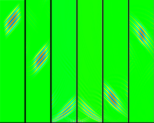
Figure 8 illustrates three representative patterns. Of these, figure 8(a–c) corresponds to the case where there is no critical layer and hence no over-reflection occurs ( $R=1$). It can be observed that the amplitudes of the incident wave in figure 8(a) and the reflected wave in figure 8(b) are equal. Meanwhile, we observe from these panels the effect of shear layers on the direction of acoustic wave propagation. This effect is caused by the significant velocity gradient close to the wall. In addition, a slight increase in the amplitude of the acoustic wave near the wall is detected.
Eigenfunctions of the incident (a,d,g) and reflected (b,e,h) acoustic waves and equation (2.31) (c,f,i) for Mach number  $M=4$ and wavenumber
 $\alpha =2$: (a–c) for frequency
 $\omega =2.88$ (
 $\phi \approx 80^{\circ }$) and
 $R=1$; (d–f) for frequency
 $\omega =0.58$ (
 $\phi \approx 30^{\circ }$) and
 $R=1.08$; and (g–i) for frequency
 $\omega =1.35$ (
 $\phi \approx 68^{\circ }$) and
 $R=1.04$. The black dashed line stands for the location of the critical layer
 $y_c$. The angle of propagation in the free stream
 $\varTheta$ according to (2.22) is shown for incident waves.

Figure 8(d–f) and figure 8(g–i) correspond to the case of over-reflections. Figure 8(g–i) coincides with the occurrence of the resonant over-reflection, but the over-reflection coefficient only produces local peaks in  $R$. Thus, the over-reflection coefficient for figure 8(g–i) is less than the non-resonant over-reflection coefficient for figure 8(d–f). Observing the second and third rows, different patterns of over-reflection are detected. In the second row, particularly visible in figure 8(f), the amplitude of the acoustic wave near the wall is less than the amplitude of the acoustic wave in the free stream. In contrast, in the third row, i.e. figure 8(g–i), the amplitude of the acoustic wave near the wall is much greater than the amplitude of the acoustic wave in the free stream.
In addition, from figures 8(f) and 8(i), we find that the amplitude of acoustic waves is relatively small near the critical layer. This suggests that the critical layer has an attenuating effect on acoustic waves, in agreement with the conclusion proposed in Campos & Serrão (Reference Campos and Serrão1998). It is important to point out that the transformation between the second and third rows occurs continuously and smoothly with variations of  $\omega$, i.e. their difference is not due to the resonant over-reflection. In the vicinity of
 $\omega =1.35$, i.e. the region where non-resonant over-reflections occur, e.g.
 $\omega =1.32$, the pattern of the eigenfunction remains similar to the third row. Conversely, the pattern of the eigenfunction of the resonant over-reflection always resembles that in the third row, i.e. the amplitude near the wall is much greater than that in the free stream. This suggests, from another point of view, that resonant over-reflection (instability) is a special case of over-reflections.
In figure 8(g–i), we note a pattern of the eigenfunction similar to that of the unstable modes in Zhang & Oberlack (Reference Zhang and Oberlack2021). Through figure 8(g–i) we clearly observe the acoustic waves trapped between the first relative sonic line and the wall, similar to the surface wave (mode) (see e.g. Rienstra & Hirschberg Reference Rienstra and Hirschberg2020). (For a detailed definition of the relative sonic line, see e.g. Knisely (Reference Knisely2018). Here it means that the relative Mach number equals minus one.) This indicates that complex reflections and refractions occur near the wall. In contrast to the non-resonant over-reflection in figure 8(d–f), on the one hand, the distance between the first sonic line and the wall is not sufficient to generate strong complex reflections and refractions, and, on the other hand, the attenuating effect of the critical layer covers this distance. Thus, as read from the pattern in the second row of figure 8, no related instability may exist. As the critical layer moves away from the wall, the surface wave (mode) becomes apparent, where complex reflections and refractions occur near the wall, which is an infallible sign of a related unstable mode at a particular frequency.
The above inference is confirmed by figure 9. Similar to the setting in figure 8, figure 9 shows the eigenfunction of acoustic waves but at the Mach number  $M=5$, where figure 9(a–c) for
 $\alpha =2.2$ corresponds to the maximum value of the peak in figure 5(c). The enhancement of the reflected waves can be clearly observed by the colour gradient. Meanwhile, the amplitudes near the wall are much greater than in the remaining domain, where complex reflection and refraction occurs. This region is necessary to induce instability as was shown in Zhang & Oberlack (Reference Zhang and Oberlack2021). From figure 9(d–f) for
 $\alpha =0.1$, we observe similar acoustic wave propagation to the second pattern in figure 8. Small wavenumbers
 $\alpha$ do not allow for complex reflections and refractions that increase the amplitude near the wall. Therefore, despite the large over-reflection coefficient
 $R=2.42$, no resonant over-reflections could occur with the near-wall pattern in figure 9(d–f), i.e. no unstable modes exist related to these parameters.
Eigenfunctions of the incident (a,d) and reflected (b,e) acoustic waves and equation (2.31) (c,f) for Mach number  $M=5$: (a–c) for wavenumber
 $\alpha =2.33$, frequency
 $\omega =1.34$ (
 $\phi \approx 70^{\circ }$) and
 $R=1.46$ corresponding to the global maximum value in figure 5(c); and (d–f) for wavenumber
 $\alpha =0.1$, frequency
 $\omega =0.078$ (
 $\phi \approx 75^{\circ }$) and
 $R=2.42$. The black dashed line stands for the location of the critical layer
 $y_c$. The angle of propagation in the free stream
 $\varTheta$ according to (2.22) is shown for incident waves.

4. Conclusion and outlook
We investigate the over-reflection of acoustic waves in boundary layer flows based on the exact solution to the PBE for an exponential velocity profile. The over-reflection coefficient is shown in detail as a function of problem parameters, i.e. Mach number  $M$, wavenumber
 $\alpha$ and incident angle
 $\phi$. Over-reflection exhibits very different patterns depending on small, moderate and large wavenumbers
 $\alpha$. In comparison with small
 $\alpha$, moderate
 $\alpha$ lead to smaller over-reflection coefficients, while at the same time a reduced sensitivity to the Mach number is observed. However, an increase in
 $\alpha$ leads to the occurrence of resonant over-reflections. The resonant over-reflection coefficient initially induces a local peak, which increases with
 $\alpha$ and becomes a global maximum value around
 $\alpha =1.3$. Thereafter, the peak continues to increase, reaches a maximum value around
 $\alpha =2$ before it gradually decreases. Although the resonant over-reflection attenuates as
 $\alpha >2$, the resonant over-reflection is more noticeable relative to the non-resonant over-reflection. In other words, for large
 $\alpha$, over-reflection is hard to detect. At specific resonant frequencies, however, resonant over-reflections may be observed.
Both over-reflection and temporal–spatial instability reflect the extraction of energy of acoustic waves/modes from shear flows. The phenomenon of over-reflection is obtained from a purely acoustic point of view. The inviscid instability, in contrast, is obtained from a stability point of view. For acoustic wave disturbances that gain energy from shear flows, this will manifest itself in the form of an over-reflection. Stability analysis, from the point of view of boundary conditions, is based on two strict boundary conditions, resulting in an eigenvalue problem. For acoustics, in contrast, only a rigid-wall boundary condition is inferred and the relatively weak boundary condition of the presence of acoustic waves at infinity is brought in. Thus, instability can also be seen as a special form of over-reflection. This is evident from the fact that the eigenvalue equation of the temporal–spatial stability problem coincides with the special case in (2.32).
In this paper, the investigation is carried out mainly from an acoustic point of view. From the results, we confirm that the resonant frequencies generated by unstable modes are not just the first unstable mode, but also higher unstable modes lead to an enhancement of the over-reflection, i.e. the resonant over-reflection. This is demonstrated by comparing the eigenvalues of the unstable modes with the unusually high over-reflection coefficients. The eigenvalues obtained in the stability analysis represent the resonant frequencies, which are properties of the boundary layer flow. Around these frequencies, acoustic waves or disturbances can absorb more energy from the base flow. By comparing the eigenfunctions of acoustic waves, we identify the mechanism by which resonant over-reflection occurs. The acoustic waves gain energy from the base flow at the critical layer, accumulate energy in the area close to the wall and form an area with complex reflections and refractions, and subsequently induce the resonant over-reflection. The relevant mechanism can also be observed in the study on stability in Zhang & Oberlack (Reference Zhang and Oberlack2021).
In the present analysis, we show that the critical layer plays an important role in the energy exchange between waves and shear flows. The critical layer is the most effective location for energy exchange to occur. This is due to the phase velocity of the disturbance or wave being equal to the velocity of the base flow there. Thus the critical layer is the most likely location to have interaction. We further prove that, in supersonic boundary layer flows with a critical layer over a rigid wall, the jump of the quasi-invariant at the critical layer always causes an amplification of the reflected waves, i.e. reflected waves extract energy from the base flow. The presence or absence of a critical layer, therefore, determines whether an over-reflection or instability occurs, which is validated by our results.
We further establish an extended unitarity condition between the over-reflection coefficient and the jump of the quasi-invariant at the critical layer. This condition shows that the over-reflection coefficient is closely linked to the acoustic perturbation at the critical layer.
The three patterns in figure 8 give insight into practical noise control. Avoiding noise from boundary layer flows requires countermeasures that are based on the physical properties pointed out above. Specifically, measures of the noise reduction are based on the actual location where the noise reduction is required, e.g. civil aviation cabin noise reduction or emission noise reduction. Considering the emission noise reduction, i.e. to the free stream out of the boundary layer, then over-reflection should be avoided. If only the near-wall noise reduction is considered, e.g. noise into the cabin, the second pattern in figure 8 has advantages due to a weakened amplitude (loudness) of acoustic waves near the wall. In some specific parametric intervals, however, the third pattern in figure 8 would occur. This pattern should be avoided in noise control, as the amplitude (loudness) of acoustic waves is amplified both near the wall and in the free stream, and may induce instability.
To achieve this, one possible way is to control the wavenumber in terms of the results in §§ 3.1 and 3.2 and keep the frequency smaller than certain thresholds according to (2.17) and figure 2. This could be achieved by a wave filter, which changes the wavelength and the frequency. A device that exactly achieves these effects has been applied in the inlet and outlet of a jet engine (Henderson Reference Henderson2010).
Another feasible way to control the noise is to change the wall condition, i.e. the acoustic wall impedance. The investigation of the propagation of acoustic waves in boundary layer flows with acoustic impedance conditions is a popular topic in recent years, which stems from an interest in noise regulation by using acoustic liners in aircraft engines. Representative work includes Rienstra & Darau (Reference Rienstra and Darau2011) and Brambley (Reference Brambley2011), who proposed modified Myers conditions with a finite boundary layer thickness, thus avoiding the ill-posed problem in the time domain. Based on these, Gabard (Reference Gabard2013) gave the reflection coefficient of acoustic waves in half-space flows in terms of the Myers (Reference Myers1980) condition and the modified Myers conditions and investigated the effect of acoustic impedance and boundary layer thickness on it. In addition, he gave a comparison of the effect of sound absorption between results using the Myers condition and other impedance conditions, one of which is derived based on the exact solution to the PBE for a special case, i.e. a linear velocity profile. In our context, applying the acoustic impedance to replace the current rigid-wall boundary condition will result in a different equation for the reflection coefficient. In this way, the reflection coefficient can be regulated by varying the acoustic impedance to find the optimal acoustic impedance to suppress or even hinder over-reflection. A similar approach has already been applied to civil aviation. In Oppeneer (Reference Oppeneer2014), porous materials are applied to the liner wall of the auxiliary power unit of an aircraft, which attenuates the noise.
In future work, we plan to investigate the relationship between unstable modes and over-reflections by direct numerical simulations. By using different boundary conditions, we can artificially separate the stability problem from acoustic over-reflection. Physically, however, the two mechanisms should coexist and interact with each other. Therefore, we argue that acoustic over-reflection in boundary layer flow is able to induce instability, which is to be validated.
Funding
The work of Y.Z. was supported by the Deutsche Forschungsgemeinschaft (DFG, German Research Foundation): OB 96/55-1-456793479. The work of S.G. was supported by the Graduate School CE within the Centre for Computational Engineering at Technische Universität Darmstadt.
Declaration of interests
The authors report no conflict of interest.
Data availability statement
The data that support the findings of this study are openly available from the Technische Universität Darmstadt repository at https://doi.org/10.48328/tudatalib-897.
Appendix A. Critical layer
As already shown, the PBE reaches a singularity if the phase velocity in the  $x$-direction coincides with the base flow velocity, which means
 $\omega =\alpha u_0(y_c)$. This horizontal layer is called the critical layer. We will first examine the behaviour of the solution at the critical layer by using an asymptotic method, the Fuchs–Frobenius method. For this, we first employ a change of the independent variable to
 $\xi$, defined by
 \begin{equation} \xi=\frac{\omega}{\alpha}- u_0(y)=\frac{\omega}{\alpha}-(1-{\rm e}^{{-}y}), \end{equation}
such that  $y_c$ refers to
 $\xi =0$, which converts the PBE (2.9) to
 \begin{equation} \frac{{\rm d}^2\hat\rho}{{\rm d}\xi^2} -\frac{(\xi+2)\alpha-2\omega}{\xi[(\xi+1)\alpha-\omega]}\, \frac{{\rm d}\hat\rho}{{\rm d}\xi} +\frac{(M^2\xi^2-1)\alpha^4}{[(\xi+1)\alpha-\omega]^2}\,\hat\rho=0. \end{equation}
A solution of (A2) in the vicinity of  $\xi =0$ can be derived as a power series using the Fuchs–Frobenius method. Inserting the power series approach, given by
 \begin{equation} \hat\rho(\xi)=\xi^r\sum_{k=0}^{\infty}a_k\xi^k, \end{equation}
into the differential equation (A2) and sorting by powers of  $\xi$ yields the indicial equation for
 $r$. It has two roots, which read
 $r_1=3$ and
 $r_2=0$, and indicate that their difference
 $r_1-r_2=3$ is a positive integer. Following Olver et al. (Reference Olver, Lozier, Boisvert and Clark2010), a regular implementation of the method of Frobenius in this case fails to yield two independent solutions. Hence, a second independent solution contains a logarithmic term and can be constructed by
 \begin{equation} \hat{\rho}_2(\xi)=c \hat{\rho}_1(\xi) \ln(\xi) +\xi^{r_2}\sum_{k=0}^{\infty}b_k\xi^k, \end{equation}
where the constant  $c$ can be derived by re-inserting into (A2), starting with
 $b_0=a_0=1$. The first independent solution is given by
 \begin{equation} \hat{\rho}_1(\xi)=\xi^{r_1}\sum_{k=0}^{\infty}a_k\xi^k. \end{equation}
Near the critical layer, i.e.  $\xi \to 0$, the solution given by a linear combination of (A4) and (A5) is considered to the leading order, and we obtain
 \begin{equation} \hat{\rho}(\xi)=A(\xi^3+{O}(\xi^4)) +B[c (\xi^{3}+{O}(\xi^4)) \ln (\xi)+1+{O}(\xi^1)], \end{equation}
where  $A$ and
 $B$ are two constants.
Re-inserting (A6) into (A2) yields, after some algebra,
 \begin{equation} c={-}\frac{4\alpha(\alpha-\omega)+\dfrac{3\alpha^5}{\alpha-\omega}}{3(\alpha-\omega)^2}. \end{equation}
From (A6) it can be concluded that the solution tends to be a constant near the critical layer. Furthermore,  $c$ can be rewritten as
 \begin{equation} c={-}\frac{4\alpha^2\left(1-\dfrac{\omega}{\alpha}\right) +\dfrac{3\alpha^4}{1-{\omega}/{\alpha}}}{3(\alpha-\omega)^2}. \end{equation}
This shows that the constant  $c$ is, in the presence of a critical layer, always negative, since the necessary condition for the occurrence of a critical layer is that
 ${\omega }/{\alpha }\in [0,1]$. We will use this knowledge in § 2.5 to show that
 $R>1$ in this case.
Appendix B. Causality and the choice of branch cuts
As recognized by Brambley, Darau & Rienstra (Reference Brambley, Darau and Rienstra2012), the choice of branch cuts is crucial for the investigation of the critical layer. Thus, the question arises: Which criterion allows us to choose the correct branch cut? We assume a causal signal. Following Dethe, Gill & Green (Reference Dethe, Gill and Green2019): ‘causality states that the cause precedes the effects’. This means nothing other than that an effect can only be affected by the temporally previous effects, and not by the future. The causality condition can be formulated by regarding the response function in Fourier space. As shown by Dethe et al. (Reference Dethe, Gill and Green2019), a causal solution mapped by a Fourier transformation to  $\hat \rho (\omega )$ requires analyticity of the Fourier response function in the upper complex
 $\omega$ half-plane. Since
 $\xi =\omega /\alpha -u_0$, we require analyticity of the solution in the upper complex
 $\xi$ half-plane. (For simplicity, we restrict the consideration to positive values of
 $\alpha$. For negative
 $\alpha$, the consideration would be reversed, but the outcome
 $|R|>1$ stays the same since the right-hand side of (2.37) would then also change its sign.)
As shown in Appendix A, the solution  $\hat \rho$ contains a logarithmic term; thus we have to define the branch cut of the complex logarithm in the complex
 $\xi$ plane.
The logarithm of a complex number  $\xi$ is defined by
 $\textrm {{ln}}(\xi )=|\textrm {{ln}}(\xi )|+\textrm {i}\,\textrm {{arg}}(\xi )$. Since
 $\textrm {{arg}}(\xi )$ is
 $2{\rm \pi}$-periodic, we have to introduce a branch cut that ensures that, for every point
 $\xi$ in the complex plane, there is only one solution for
 $\textrm {{ln}}(\xi )$. The branch cut is chosen to be a straight line starting from the branch point
 $\xi =0$, which is a singularity of
 $\textrm {{ln}}(\xi )$.
If we choose the branch cut to be a straight line in the upper complex  $\xi$ half-plane, there would be a discontinuity of
 $\textrm {{ln}}(\xi )$, since
 $\textrm {{arg}}(\xi )$ undergoes a jump at the branch cut. However, this would contradict the causality condition, i.e. analyticity in the upper complex
 $\omega$ half-plane. Therefore, the only possible choice for the branch cut of
 $\textrm {{ln}}(\xi )$ is the red straight line in the lower complex half-plane shown in figure 10.
Regularized path of integration and choice of the branch cut.

Appendix C. Derivation of the extended unitarity condition
In this section, an extended unitarity condition given by (2.47) is derived. It gives a relation between the amplitude of density perturbation, its derivatives at the critical layer and the reflection coefficient  $R$. For this purpose, we first multiply (2.34) by
 $\hat \rho ^*$, the complex conjugate of
 $\hat \rho$, take the imaginary part of the equation (which allows us to identify the reflection coefficient on the left-hand side), integrate it and split up the resulting integrals, which yields
 \begin{equation}
\left.\mathrm{Im}\left(\frac{{\rm
d}\hat\rho}{{\rm d}{\tilde y}}
{{\hat\rho}^*}\right)\right|_{{\tilde
y}_1}^{{\tilde y}_2} ={-}\int_{{\tilde y}_1}^{{\tilde
y}_2}\mathrm{Im}\left(\frac{M^2}{(\omega-\alpha
u_0)^2}\right)|\hat\rho|^2\,{\rm d}{\tilde y}
+\int_{{\tilde y}_1}^{{\tilde
y}_2}\mathrm{Im}\left(\frac{\alpha^2}{(\omega-\alpha
u_0)^4}\right)|\hat\rho|^2\,{\rm d}{\tilde y}.
\end{equation}
In order to deal with the integrals that occur in (C1), which have a singularity at the critical layer  $y_c$, transformation of the independent variable to
 $\xi$, as given by (A1), is used again and yields
 \begin{equation}
\left.\mathrm{Im}\left(\dfrac{{\rm d}\hat\rho}{{\rm
d}{\tilde y}}
{{\hat\rho}^*}\right)\right|_{{\tilde
y}_1}^{{\tilde y}_2}
=\mathrm{Im}\left(\int_{\xi_1}^{\xi_2}\dfrac{1}{\xi^2}\,\dfrac{\alpha^2
M^2|\hat\rho|^2} {{{\rm
d}u_0}/{{\rm d}{\tilde
y}}}\,{\rm d}\xi\right)
-\mathrm{Im}\left(\int_{\xi_1}^{\xi_2}\dfrac{1}{\xi^4}\,\dfrac{\alpha^6|\hat\rho|^2}
{{{\rm d}u_0}/{{\rm
d}{\tilde y}}}\,{\rm d}\xi\right).
\end{equation}
Both integrals in (C2) have a singularity at  $\xi =0$, which corresponds to the localization of the critical layer. Provided that the parameter set induces a critical layer, the value of the imaginary part of these integrals is non-zero due to the singularity, even if the integrals contain only real values. For the treatment of integrals containing singular functions, we would like to refer to the theory of distributions in the context of generalized functions. For further literature, please see Galapon (Reference Galapon2016). The main outcome can be summarized in the Sokhotski–Plemelj–Fox theorem, given by formula (C4). Since we have to treat the singularity occurring in (C2) in a distributional context, even an integral containing only real quantities must be split up into real and imaginary parts due to the regularization process. If there is no critical layer, then there is no singularity in the integrands, the integrals are real, and the imaginary parts of these integrals vanish. Further information can be found for example in the book of Lighthill (Reference Lighthill1958).
In order to evaluate the singular integrals, i.e. regularize the singularity, a small imaginary frequency  $\textrm {i}\epsilon$ is added to the singularity, i.e.
 $\omega \to \omega +\textrm {i}\epsilon$ . Thus, weak temporal growth of the solution is allowed, consistent with the causality theory. The regularization and the chosen branch cut for the logarithmic term in the solution is shown in figure 10. It can be easily seen that a regularization of the path of integration (blue) by
 $\omega -\textrm {i}\epsilon$ would intersect with the branch cut and would thus cause another discontinuity in the integral. Therefore, the given choice
 $\omega +\textrm {i}\epsilon$ is the one that is consistent with the causality theory.
In the next step, the limit  $\epsilon \to 0$ is taken, which represents the purely acoustic case, i.e.
 \begin{align}
\left.\mathrm{Im}\left(\dfrac{{\rm d}\hat\rho}{{\rm
d}{\tilde y}}
{{\hat\rho}^*}\right)\right|_{{\tilde
y}_1}^{{\tilde y}_2} &=\lim_{\epsilon\to
0}\left(\mathrm{Im}\int_{\xi_1}^{\xi_2}\dfrac{1}{(\xi+{\rm
i} \epsilon)^2} \,\dfrac{\alpha^2 M^2|\hat\rho|^2}{{{\rm
d}u_0}/{{\rm d} {\tilde y}}}\,{\rm d}\xi\right.\nonumber\\
&\quad
\left.-\,\mathrm{Im}\int_{\xi_1}^{\xi_2}\dfrac{1}{(\xi+{\rm
i} \epsilon)^4} \,\dfrac{\alpha^6|\hat\rho|^2}{{{\rm
d}u_0}/{{\rm d} {\tilde y}}}\,{\rm d}\xi\right).
\end{align}
In order to deal with the higher-order singular integrals, the Sokhotski–Plemelj–Fox theorem described in Galapon (Reference Galapon2016) is applied, which includes the idea of separating the finite part from the divergent integral. The theorem reads as follows:
 \begin{equation} \lim_{\epsilon\to 0}\int_a^b \frac{f(x)}{(x+{\rm i}\epsilon)^{n+1}} \,{{\rm d}x} ={\rm{PV}}\int_a^b \frac{\,f(x)}{x^{n+1}}\,{{\rm d}x} -{\rm i}{\rm \pi} \frac{\,f^{(n)}(0)}{n!}, \end{equation}
if  $a<0< b$ holds. Therein,
 $\rm {PV}$ refers to Cauchy's principal value.
To fulfil this condition in (C3), the behaviour in  $\xi$ is investigated. The limits of integration, i.e.
 $y=0$ and
 $y\to \infty$, change using (A1) to
 $\xi _1=\omega$ and
 $\xi _2=\omega -\alpha$. Since the following derivation is intended to consider specifically the case of a critical layer at position
 $\xi =0$ lying within the physical area, it has to be assumed in the following that
 $\omega <\alpha$, which is the condition for the existence of a critical layer. To apply the Sokhotski–Plemelj–Fox theorem (C4), the limits of integration in (C3) are swapped, which leads to
 \begin{align}
\left.\mathrm{Im}\left(\dfrac{{\rm d}\hat\rho}{{\rm
d}{\tilde y}}
{{\hat\rho}^*}\right)\right|_{{\tilde
y}_1}^{{\tilde y}_2} &={-}\lim_{\epsilon\to
0}\left({\mathrm{Im}}\int_{\xi_2}^{\xi_1}\dfrac{1}{(\xi+{\rm
i} \epsilon)^2} \,\dfrac{\alpha^2 M^2|\hat\rho|^2}{{{\rm
d}u_0}/{{\rm d} {\tilde y}}}\,{\rm d}\xi\right.\nonumber\\
&\quad \left. -\,\mathrm{Im}\int_{\xi_2}^{\xi_1}\dfrac{1}{(\xi+{\rm i}
\epsilon)^4} \,\dfrac{\alpha^6|\hat\rho|^2}{{{\rm
d}u_0}/{{\rm d} {\tilde y}}}\,{\rm d}\xi\right),
\end{align}
where  $\xi _2<0<\xi _1$.
Since the Cauchy principal value in (C4) represents the finite part of the integral, it is, if  $f(x)$ is a real function, a real value. Since we limit to the imaginary parts of the integrals in (C5), the principal value vanishes in the application of (C4) on the right-hand side of (C5), which yields
 \begin{equation}
\left.\mathrm{Im}\left(\frac{{\rm
d}\hat\rho}{{\rm d}{\tilde y}}
{{\hat\rho}^*}\right)\right|_{{\tilde
y}_1}^{{\tilde y}_2} =\left.{\rm \pi}\left[\left(M^2\alpha^2\dfrac{{\rm d}}{{\rm
d}\xi} -\dfrac{\alpha^6}{6}\dfrac{{\rm d}^3}{{\rm
d}\xi^3}\right) \dfrac{|\hat\rho|^2}{{{\rm d}u_0}/{{\rm
d}{\tilde y}}}\right]\right|_{\xi=0}.
\end{equation}
With this, the derivation of (2.45) is complete and it has been used in (2.37) to obtain (2.47). Transforming (C6) back to the initial independent variable  $y$ and simplifying yields (2.47).
Appendix D. Data for higher unstable modes
In this section, data on the resonant frequencies for higher unstable modes are shown in the form of tables. Tables 1 and 2 show the data regarding the second and third unstable modes. Specific wavenumbers and Mach numbers are selected in order to correspond to the cases in figure 7. With these parameters, the resonant frequency  $\omega _r$, the incident angle
 $\phi$ and the over-reflection coefficient
 $R$ are given.
Values of the resonant frequency  $\omega _r$, incident angle
 $\phi$ and over-reflection coefficient
 $R$ at which the second unstable modes occur for different
 $\alpha$ and
 $M$.

Values of the resonant frequency  $\omega _r$, incident angle
 $\phi$ and over-reflection coefficient
 $R$ at which THE third unstable modes occur for different
 $\alpha$ and
 $M$.



