1. Introduction
With the development of modern medicine, minimally invasive surgery (MIS) is widely used in the clinic due to its small wounds, less blood loss, and faster recovery [Reference Wang, Chen, Xia, Qin, Liu and Ren1]. Though MIS presents significant advantages compared to open surgery, it also poses great difficulties for surgeons as they must operate through a small incision on the patient’s body, which is often called a remote center-of-motion (RCM). Therefore, it is a key issue in the design of minimally invasive surgical robots for rod-shaped surgical tools that are required to accomplish RCM motion, normally considered as a 4-dimensional (4-D) motion [Reference Kuo, Dai and Dasgupta2] as shown in Figure 1.
To achieve the kinematical property of RCM, typically, there are two ways, which can be categorized as control-based and structure-based methods [Reference Kuo, Dai and Dasgupta2]. However, the primary design principle for medical auxiliary equipment should be safety [Reference Taniguchi3]. Compared with the possible failure and error probability caused by the control-based method, a mechanically ensured RCM mechanism can exclude such dangers in nature, and therefore, RCM mechanism is preferred in the design of MIS assist robots [Reference Lin, Guo and Cheng4–Reference Li, Herve and Huang5].
Concerning the structure of RCM manipulators, Kuo and Dai classify RCM mechanisms into eight types [Reference Kuo and Dai6]. Among these types, parallelograms, spherical linkages [Reference Essomba and Nguyen7], circular tracking arcs [Reference Cao, Xu, Rao and Ding8], and parallel mechanisms (PM) are more widely and intensively addressed. The 1-D double parallelogram-based RCM mechanism is widely adopted in MIS robots, including the da Vinci robot system [Reference Ballantyne and Moll9]. Since a Star-like robot [Reference Hervé10] first used the concept of the planar parallelogram in its design, parallelogram-based mechanisms have attracted the attention of researchers [Reference Liu and Wang11]. In the field of MIS assisting robots, the Dionis robot [Reference Beira, Santos-Carreras, Sengul, Samur, Clavel and Bleuler12] was designed based on the parallelogram, and it can fulfill the 3R1T motion required in MIS. In addition, Li [Reference Li, Wang, Wang, He and Zhang13–Reference Li, Wang, Wang and He14] proposed a new mechanism that has a similar function to the double parallelogram. Many other novel mechanisms that take advantage of parallelograms have also been synthesized [Reference Wang, Zhang and Ding15–Reference Zong, Pei, Yu and Bi21].
Required motion of the end-effector in MIS.

The design of RCM mechanisms also employs PMs, which are preferred due to their higher stiffness and precision. Li [Reference Li, Zhang, Müller and Wang22] proposed a family of RCM PMs based on the kinematic property of intersecting motion planes. Kumar [Reference Kumar, Piccin and Bayle23] presented a task-based methodology to synthesize RCM PMs with 2T2R motion in order to achieve greater adaptability. Yasir [Reference Yaşır and Kiper24–Reference Yaşır, Kiper and Dede25] found a family of nonparasitic 2R1T PMs with screw theory, which is a constraint-based type synthesis method [Reference Huang and Li26] and select one configuration for further kinematic analysis. Huang [Reference Huang, Guang, Yang and Su27] used a modified screw theory method yielding PMs with an optimal wrench system. Using the motion-based synthesis method [Reference Li and Herve28–Reference Li and Herve30], Lie-group, a new family of 3R1T RCM PMs with fixed linear actuators featuring lower movement inertia and higher stiffness was synthesized by Li [Reference Li, Herve and Huang5].
However, it should be pointed out that there are still shortcomings in spite of much literature addressed in the field. It is easy to utilize a serial arm to conduct preoperative positioning of RCM in practical applications of MIS assist robots. However, the accuracy of this adjustment is totally dependent on the control accuracy of the serial arm. By introducing a PM in this process in view of the PM’s advantages to the serial arm, accuracy can be improved, and the cumulative error can be eliminated. Inspired by a reconfigurable manufacturing system [Reference Chi and Zhang31], a double-stage configuration is employed. It is a special kind of reconfigurable structure for its continuous reconfiguration process [Reference Huang, Zhang, Zou, Ye and Kong32]. This configuration provides greater flexibility and adaptability for the mechanism [Reference Huang, Guo, Zhang, Han and Tang33] due to the connectivity between the two stages, allowing for possible adjustments. To the best of our knowledge, there are limited amount of literature that applies a double-stage configuration to realize movable RCM.
This paper focuses on the type synthesis of double-stage PMs with movable RCM, taking advantage of the double-stage configuration to achieve the positioning of RCM. The contribution of this paper can be concluded as follows: (1) The concept of PM with movable RCM is designed and addresses the issue by introducing a double-stage structure. (2) A comprehensive method that integrates configuration evolution based on Lie-group has been proposed, and synthesis is conducted with this method. (3) Numerous new double-stage PMs with movable RCM are obtained.
The organization of this paper is as follows. Section 2 presents the concept of double-stage PMs with movable RCM and designs the overall procedure for the type synthesis. Sections 3 and 4 conduct the type synthesis of two stages of PMs separately. The design of connectivity between the two stages and the construction of double-stage PMs with movable RCM are accomplished in Section 5. Conclusions are drawn in Section 6.
2. General procedure for the type synthesis of double-stage PMs with movable RCM
2.1. Type synthesis with configuration evolution based on Lie-group
The methods available for the type synthesis of PM can be generally divided into two categories: finite motion-based methods represented by Lie-group theory [Reference Li and Herve30, Reference Li and Herve34] and instantaneous constraint-based methods represented by screw theory [Reference Ju, Xu, Meng and Cao35–Reference Kong and Gosselin37]. Compared to other methods, Lie-group is an effective method for the type synthesis of PMs because, in contrast to constraint-synthesis methods, which require proof of the non-instantaneous nature of the motion, Lie-group represents the continuous motion of a rigid body [Reference Li38–Reference Hervé39].
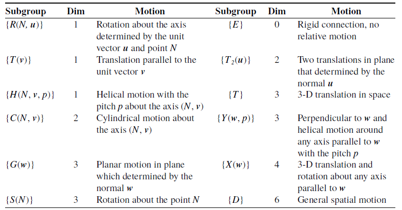
According to Lie-group, the 6-D space motion of a rigid body has an algebraic structure, which is denoted by {D}, and its subset can also be a subgroup or submanifold of {D} as listed in Table I, which means that Lie-group can represent any arbitrary rigid body’s finite motion. Thus, this paper carried out the type synthesis of double-stage PMs with movable RCM based on Lie-group and the characteristics of subgroups.
Lie subgroups and its explanations.

Configuration evolution is an experience-based design methodology and is often combined with constraint screw theory in the type synthesis process [Reference Fan, Liu and Zhang40]. It is usually performed in two paths as shown in Figure 2: local evolution based on limb structure and overall evolution based on PM structure. The process of local evolution is adding kinematic joints to the limb or replacing a certain kinematic joint of the limb with a composite joint that has a higher degree of freedom (DoF) to obtain a feasible limb. This is similar to the way in which subgroups are added or replaced based on Lie-group [Reference Li and Herve30]. Therefore, in this paper, local evolution is performed under the framework of Lie-group. Overall evolution based on the whole PM structure that replacing all the limbs in a PM with evolved limbs is suitable for more intuitive cases. It is effective when the mechanism has a simpler motion pattern, and we don’t need to obtain all the possible structures.
It is worth noting that adopting configuration evolution simplifies the type synthesis process compared to most synthesis methods but often requires further validation to verify the motion pattern of the resultant mechanism. Therefore, Lie-group are introduced to the type synthesis process of configuration evolution, which retains the simplicity of the configuration evolution while using Lie-group to ensure the motion continuity of the resultant mechanisms.
The process of configuration evolution.

Different topological arrangements for PMs.

2.2. Concept of double-stage PMs with movable RCM
A PM is typically characterized by multiple kinematic limbs that are connected to the end-effector and output desired motion. When it has the feature of RCM, it becomes an RCM PM. It is noteworthy that the rotation around the surgical tool is usually achieved by itself, while MIS often requires a surgical tool with 4-D motion as shown in Figure 1. Therefore, this paper will focus on the type synthesis of double-stage PMs with movable RCM, which can fulfill 2R1T RCM motion, that is, two rotations around u -axis and v -axis and one translation along w -axis as shown in Figure 1, not including the rotation around w -axis.
A normal RCM PM can only realize a required RCM motion; however, when it comes to the adjusting of RCM position, an extra equipment is needed based on the literature referred to above [Reference Kumar, Piccin and Bayle23]. To solve this problem, a double-stage configuration is employed. The scheme of a double-stage PM is shown in Figure 3(c), which has two output platforms and the two stages that can realize different functions in practical applications. Based on the order of assembly, the PM close to the base is assembled first and therefore defined as the primary PM. In this paper, the primary moving platform, that is, ED1 in Figure 3(c), is expected to realize the function of adjusting the position of the RCM, while the secondary moving platform, that is, ED2 in Figure 3(c), realizes the RCM motion.
Compared with the conventional configuration of general PM in Figure 3(a) and hybrid PM in Figure 3(b), the double-stage PM allows for greater flexibility and a larger workspace by adjusting the position of the RCM through the primary PM and at the same time maintaining the RCM motion of the secondary PM. Therefore, the double-stage configuration has an advantage over general structures in realizing the positioning of RCM. It provides more flexibility and adaptability in real applications because of the possible adjustment between the two stages.
The connectivity between the two stages is also an important issue in the design of double-stage PM, for it can provide continuous various configurations [Reference Chi and Zhang31]. Further design of the connectivity between the two stages, which is defined as connection style, will be done after the configuration of the two stages has been determined.
Synthesis process of double-stage PM with movable RCM.

2.3. General methodology for the type synthesis of double-stage PMs with movable RCM
In this paper, the target motion pattern of secondary PM is two pivoted rotations and the depth of penetration (2R1T) based on RCM. The primary PM provides the mechanism with the ability to move RCM in space, which can be divided into 1T, 2T, and 3T motions. The general methodology for the type synthesis of double-stage PMs with movable RCM using configuration evolution based on Lie-group is described in Figure 4, whose detailed descriptions are in the following:
Step 1: Target motion analysis.
In this step, the target motion of the primary PM or the secondary PM, which is denoted as M TA , is analyzed based on Lie-group before the synthesis process, and the corresponding expression of M TA is described in the form of Lie-group.
Step 2: Limb generation and construction of the secondary PM.
Lie-group would be used to generate limb bonds for the target motion of the secondary PM. In this process, M TA are required to be the subset of the motion of i -th limb M Li , which is rule 1 in Eq. (1). Conducting the limb synthesis with these limb bonds, the secondary PM can be constructed following rule 2 in Eq. (1).
 \begin{align} \left\{\begin{array}{l} \left\{M_{TA}\right\}\subseteq \left\{M_{{L_{\mathrm{i}}}}\right\}\left(\text{rule }1\right)\\[3pt] \left\{M_{TA}\right\}=\overset{n}{\underset{i=1}\cap }\left\{M_{{L_{\mathrm{i}}}}\right\}\left(\text{rule }2\right)\\[3pt] \left\{M_{TA}\right\}\subseteq \left\{M_{EPM}\right\}\left(\text{rule }3\right) \end{array}\right. \end{align}
Step 3: Type synthesis of the primary PM.
In this step, primary PMs with different translational DoFs would be synthesized based on the simplest structure, which can be seen as the original PM. Through configuration evolution of original limbs and replacing the original limbs with those evolved ones, the motion of evolved PM, which is denoted as M EPM , should satisfy rule 3 in Eq. (1).
Step 4: Connection style design and construction of double-stage PMs with movable RCM.
Having the available structure of the two stages synthesized above, the connection style should enable the two stages to preserve the expected motion pattern, which means maintaining the assembly relationship for each stage. After designing the connection style based on the assembly conditions, all the double-stage PMs with movable RCM will be constructed.
3. Type synthesis of the secondary PM
After the illustration of the general methodology for the type synthesis and the introduction of the concept of double-stage PMs into the synthesis process, the type synthesis of the secondary PM will be conducted first. Using the method of adding subgroup and submanifold way of configuration evolution based on Lie-group [Reference Hervé39], the type synthesis of the secondary PM will be presented in detail in this section.
3.1. Analysis of target motion requirement
2R1T motion can be generally represented by three expressions as follows:
-
1. {R(N 1, i )}{R(N 2, j )}{T( w )}
-
2. {R(N 1, i )}{T( w )}{R(N 2, j )}
-
3. {T( w )}{R(N 1, i )} {R(N 2, j )}
However, it is crucial to recognize that not all these three expressions are capable of realizing 2R1T motion for RCM, not including the rotation around w -axis. In this motion, the two rotations must intersect at a fixed point, the RCM. The axes of the two rotations must be continuous despite the translation. Therefore, the latter two expressions are incompatible with this specific motion. In accordance with the virtual chain theory [Reference Kong and Gosselin41], this scenario can be classified as either an [RR] s P-equivalent chain or an UP-equivalent chain [Reference Ye, Li and Chai42].
Thus, the target motion accomplishes the transformation, which can be given as [Reference Li and Herve28]:
 \begin{align} \begin{array}{ll} M\rightarrow M' & =O+\exp \left(\varphi {\boldsymbol{u}}\times \right)\left(OM_{R}\right)\\[3pt] & =O+\exp \left(\varphi {\boldsymbol{u}}\times \right)\exp \left(\psi {\boldsymbol{v}}\times \right)\left(OM+t{\boldsymbol{w}}\right)\\[3pt] & =O+t\exp \left(\varphi {\boldsymbol{u}}\times \right)\exp \left(\psi {\boldsymbol{v}}\times \right){\boldsymbol{w}}+\exp \left(\varphi {\boldsymbol{u}}\times \right)\exp \left(\psi {\boldsymbol{v}}\times \right)\left(OM\right) \end{array} \end{align}
The real number
t
is the amplitude of the translation, and
 $\psi$
and
 $\varphi$
are two rotation angles around the RCM point.
u
,
v
, and
w
are three orthogonal unit vectors.
The displacement M→M
′ is the product of two rotations making the transformation from M to M
R
first, which can be expressed by
 $M \rightarrow M_{R} = O + \text{exp}(\varphi{\boldsymbol{u}}\!\times\!)\text{exp}(\psi{\boldsymbol{v}}\!\times\!)(OM) $
, and it is followed by a translation
 $M_{R} \rightarrow M^{\prime} = M_{R} + {\boldsymbol{t}}\text{exp}(\varphi{\boldsymbol{u}}\!\times\!)\text{exp}(\psi{\boldsymbol{v}}\!\times\!){\boldsymbol{w}} $
. And the translation vector is
w
, which changes with the two rotations.
Synthesis of limb bonds with different degree of freedoms.

3.2. Type synthesis of kinematic limb chain
To make sure the moving platform has the mobility of target motion, the intersection of all the kinematic bonds [Reference Martı´nez and Ravani43] produced by all limb chains should satisfy
 \begin{align} \overset{n}{\underset{i=1}\cap }\left\{M_{{L_{i}}}\right\}=\left\{R\left(O,{\boldsymbol{u}}\right)\right\}\left\{R\left(O,{\boldsymbol{v}}\right)\right\}\left\{T1\left({\boldsymbol{w}}\right)\right\}\left(n=3\right) \end{align}
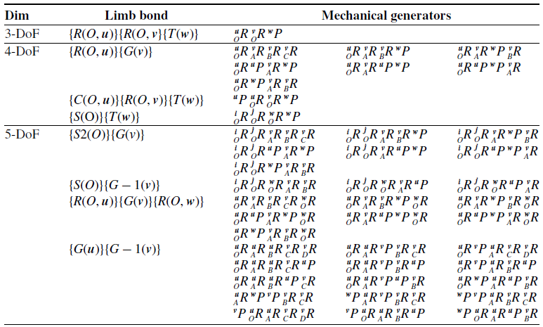
Depending on the DoF, limb chains can be classified into four categories: Dim ({M Li })=3, Dim ({M Li })=4, Dim ({M Li })=5, and Dim ({M Li })=6. Since a 6-DoF limb can achieve the general spatial rigid motion and make no constraint to the end-effector, the synthesis process of 6-DoF limb chains will be omitted [Reference Qi, Sun, Song and Jin44].
The detail of the general process is illustrated in Figure 5. All possible 4-DoF limb bonds can be obtained by adding different 1-D subgroups on both sides of the 3-DoF limb bond {R(O, u )}{R(O, v )}{T( w )}, and the same goes for 5-DoF limb bonds. Having all the limb bonds synthesized, equivalent expressions can be generated, and the redundant mobility is supposed to be eliminated. Furthermore, all the mechanical generators can be obtained by using proper joints to replace the corresponding displacement group in the expression.
Category 1: Dim ({M Li })=3
For 3-DOF limb, {M
Li
}={R(O,
u
)}{R(O,
v
)}{T(
w
)} is the only limb bond, and its corresponding mechanical generator is a 3-DoF
 ${{}^\boldsymbol{\kern1pt u}_O}\, R\,{{}^\boldsymbol{\kern1pt v}_O} \, R\,^{w}P $
limb, where
 ${{}^\boldsymbol{\kern1pt u}_O}\, R$
indicates a rotation around an axis parallel to the unit vector
u
and passing through the point O and
 ${}^{\mathit{w}}{\mathit{P}}{}$
represents a translation whose axis is parallel to the unit vector
w
.
Category 2: Dim ({M Li })=4
-
a. {R(O, u )}{G( v )}
By adding a 1-D translational subgroup {T( t )} to the right of {R(O, u )}{R(O, v )}{T( w )} yields:
 \begin{align} \left\{M_{{L_{i}}}\right\} & =\left\{R\left(O,{\boldsymbol{u}}\right)\right\}\left\{R(O,{\boldsymbol{v}}\right\}\left\{T\left({\boldsymbol{w}}\right)\right\}\left\{T\left({\boldsymbol{t}}\right)\right\}\nonumber\\[3pt] & =\left\{R\left(O,{\boldsymbol{u}}\right)\right\}\left\{G\left({\boldsymbol{v}}\right)\right\}\left(\mathrm{if}\left({\boldsymbol{t}}\bot {\boldsymbol{v}}\right)\right) \end{align}
Similarly, adding a 1-D rotational subgroup {R(A, t )}, which means a rotation about the axis determined by the unit vector t and a random point A, to the right of {R(O, u )}{R(O, v )}{T( w )} leads to the same result while the condition t is parallel to v :
 \begin{align} \left\{M_{{L_{i}}}\right\} & =\left\{R\left(O,{\boldsymbol{u}}\right)\right\}\left\{R(O,{\boldsymbol{v}}\right\}\left\{T\left({\boldsymbol{w}}\right)\right\}\left\{R\left(A,{\boldsymbol{t}}\right)\right\}\nonumber\\[3pt] & =\left\{R\left(O,{\boldsymbol{u}}\right)\right\}\left\{G\left({\boldsymbol{v}}\right)\right\}\left(\mathrm{if}\left({\boldsymbol{t}}\parallel {\boldsymbol{v}}\right)\right) \end{align}
A planar gliding displacement subgroup {G( v )} can be decomposed into seven equivalent forms totally [Reference Lee and Hervé45], and the corresponding mechanical generators are listed in Table II. The notations have the same meaning as in category 1.
Mechanical generators of {G(v)}.

-
b. {C(O, u )}{R(O, v )}{T( w )}
Adding a 1-D translational subgroup to the left of the 3-DoF limb yields a 4-DoF limb bond {C(O, u )}{R(O, v )}{T( w )}. The blue-colored {C(O, u )} and {S(O)} in Figure 5 can be decomposed into 1-D subgroups as {G( v )} . Mechanical generators of {C(O, u )} are shown in Table III. It should be noted that the helical joints are not considered in the subsequent process due to the difficulty of assembly.
Mechanical generators of {C(O, u)}.

(c) {S(O)}{T( w )}
Notice that {R(O, u )}{R(O, v )} can be seen as a submanifold of {S(O)}, adding a 1-D rotational subgroup to the left of {R(O, u )}{R(O, v )}{T( w )} yields {S(O)}{T( w )}, which is actually a SP- equivalent limb.
Category 3: Dim ({M Li })=5
Similarly, by adding a 1-D displacement subgroup to the 4-DoF limb bonds, we can get 5-DoF limb bonds in three specific forms:
-
a. {G( u )}{G( v )}
Adding a 1-D translational subgroup {T( v )} to the right side or the left side of the 4-DoF limb bond {R(O, u )}{G( v )} can lead to the 5-DoF limb bond {X( u )}{ X ( v )} or {G( u )}{G( v )}, which can be proved in Eqs. (6) and (7).
 \begin{align} \begin{array}{ll} \left\{R\left(O,{\boldsymbol{u}}\right)\right\}\left\{G\left({\boldsymbol{v}}\right)\right\}\left\{T\left({\boldsymbol{v}}\right)\right\} & =\left\{R\left(O,{\boldsymbol{u}}\right)\right\}\left\{X\left({\boldsymbol{v}}\right)\right\}\\[3pt] & =\left\{R\left(O,{\boldsymbol{u}}\right)\right\}\left\{T\right\}\left\{R\left(A,{\boldsymbol{v}}\right)\right\}\\[3pt] & =\left\{R\left(O,{\boldsymbol{u}}\right)\right\}\left\{T\right\}\left\{T\right\}\left\{R\left(A,{\boldsymbol{v}}\right)\right\}\\[3pt] & =\left\{X\left({\boldsymbol{u}}\right)\right\}\left\{X\left({\boldsymbol{v}}\right)\right\} \end{array} \end{align}
 \begin{align} \begin{array}{ll} \left\{T\left({\boldsymbol{v}}\right)\right\}\left\{R\left(O,{\boldsymbol{u}}\right)\right\}\left\{G\left({\boldsymbol{v}}\right)\right\} & =\left\{T\left({\boldsymbol{v}}\right)\right\}\left\{R\left(O,{\boldsymbol{u}}\right)\right\}\left\{T\left({\boldsymbol{w}}\right)\right\}\left\{T\left({\boldsymbol{u}}\right)\right\}\left\{R\left(A,{\boldsymbol{v}}\right)\right\}\\[3pt] & =\left\{T\left({\boldsymbol{v}}\right)\right\}\left\{R\left(O,{\boldsymbol{u}}\right)\right\}\left\{T\left({\boldsymbol{w}}\right)\right\}\left\{T\left({\boldsymbol{w}}\right)\right\}\left\{T\left({\boldsymbol{u}}\right)\right\}\left\{R\left(A,{\boldsymbol{v}}\right)\right\}\\[3pt] & =\left\{G\left({\boldsymbol{u}}\right)\right\}\left\{G\left({\boldsymbol{v}}\right)\right\} \end{array} \end{align}
{G( u )}{G( v )} is often referred to as a doubly planar bond or a G–G bond, which is reducible for there exists a redundant displacement subgroup. It is equal to {X( u )}{ X ( v )}, which is often called as double Schoenflies motion or X-X motion for brevity [Reference Lee and Hervé45]. The redundancy of the {T( w )} can be removed in several ways [Reference Lee and Hervé46].
Further, there are typically two irreducible forms of {G( u )}{G( v )}, which are {G-1( u )}{G( v )} and {G( u )}{G-1( v )}. {G-1( u )} is a 2-D submanifold included in the 3-D subgroup {G( u )} and the same for {G-1( v )}. Such an equivalence can be proved as follows:
 \begin{align} \left\{G\left({\boldsymbol{u}}\right)\right\}\left\{G\left({\boldsymbol{v}}\right)\right\} & =\left[\left\{R\left(A,{\boldsymbol{u}}\right)\right\}\left\{R\left(B,{\boldsymbol{u}}\right)\right\}\left\{R\left(C,{\boldsymbol{u}}\right)\right\}\right]\left[\left\{T\left({\boldsymbol{w}}\right)\right\}\left\{T\left({\boldsymbol{u}}\right)\right\}\left\{R\left(D,{\boldsymbol{v}}\right)\right\}\right] \end{align}
in which [{R(A,
u
)}{R(B,
u
)}{R(C,
u
)}]{T(
w
)}={G(
u
)}{T(
w
)}={G(
u
)} because of the product closure in the subgroup {G(
u
)} and {T(
w
)}
 $\subset$
{G(
u
)}. {G-1(
u
)} can be obtained by the removal of one factor in {G(
u
)}. It has three forms: {R(A,
u
)}{T(
r
)}, {R(A,
u
)}{R(B,
u
)}, or {T(
r
)}{R(A,
u
)}. Since there is no significant kinematic difference between the two irreducible limb bonds, {G-1(
u
)}{G(
v
)} is omitted in the subsequent enumeration.
-
b. {S(O)}{G( v )}
Except for the aforementioned G–G bond, another 5-DoF limb bond is the S–G or G–S bond, which is called as planar-spherical bond. For these two limb bonds are kinematical inverse to each other, only {S(O)}{G( v )} is considered in this paper. Adding either a 1-D translational subgroup or a 1-D rotational subgroup to the left of the 4-DoF limb bond {S(O)}{T( w )} can yield {S(O)}{G( v )}, as proved in Eqs. (9) and (10).
 \begin{align} \begin{array}{ll} \left\{S\left(O\right)\right\}\left\{T\left({\boldsymbol{w}}\right)\right\}\left\{T\left({\boldsymbol{u}}\right)\right\} & =\left\{R\left(O,{\boldsymbol{i}}\right)\right\}\left\{R\left(O,{\boldsymbol{j}}\right)\right\}\left\{R\left(O,{\boldsymbol{v}}\right)\right\}\left\{T\left({\boldsymbol{w}}\right)\right\}\left\{T\left({\boldsymbol{u}}\right)\right\}\\[3pt] & =\left\{R\left(O,{\boldsymbol{i}}\right)\right\}\left\{R\left(O,{\boldsymbol{j}}\right)\right\}\left\{R\left(O,{\boldsymbol{v}}\right)\right\}\left\{R\left(O,{\boldsymbol{v}}\right)\right\}\left\{T\left({\boldsymbol{w}}\right)\right\}\left\{T\left({\boldsymbol{u}}\right)\right\}\\[3pt] & =\left\{S\left(O\right)\right\}\left\{G\left({\boldsymbol{v}}\right)\right\} \end{array} \end{align}
 \begin{align} \begin{array}{ll} \left\{S\left(O\right)\right\}\left\{T\left({\boldsymbol{w}}\right)\right\}\left\{R\left(A,{\boldsymbol{v}}\right)\right\} & =\left\{R\left(O,{\boldsymbol{i}}\right)\right\}\left\{R\left(O,{\boldsymbol{j}}\right)\right\}\left\{R\left(O,{\boldsymbol{v}}\right)\right\}\left\{T\left({\boldsymbol{w}}\right)\right\}\left\{R\left(A,{\boldsymbol{v}}\right)\right\}\\[3pt] & =\left\{R\left(O,{\boldsymbol{i}}\right)\right\}\left\{R\left(O,{\boldsymbol{j}}\right)\right\}\left\{R\left(O,{\boldsymbol{v}}\right)\right\}\left\{R\left(O,{\boldsymbol{v}}\right)\right\}\left\{T\left({\boldsymbol{w}}\right)\right\}\left\{R\left(A,{\boldsymbol{v}}\right)\right\}\\[3pt] & =\left\{S\left(O\right)\right\}\left\{G\left({\boldsymbol{v}}\right)\right\} \end{array} \end{align}
where i and j are two independent unit vectors in the plane determined by point O and unite vector v and A is an arbitrary point in space that does not coincide with O.
There is a redundant factor {R(O, v )} in the S–G bond, and two irreducible limb bonds can be obtained by removal of redundancy, {S2(O)}{G( v )} and {S(O)}{G-1( v )}. {S2(O)} is a 2-D submanifold included in the 3-D subgroup {S(O)}.
-
c. {R(O, u )}{G( v )}{R(O, w )}
In addition to the above two 5-DoF limb bonds, a 5-DoF limb bond, {R(O, u )}{G( v )}{R(O, w )}, can be obtained by adding a 1-D rotational subgroup to the left of the limb bond {R(O, u )}{G( v )}.
Based on the analysis above, all mechanical generators with different DoFs are listed in Table IV. Considering the value of practical applications, forms with more than two prismatic joints are neglected [Reference Kumar, Piccin and Bayle23].
Mechanical generators of all the limb bonds.

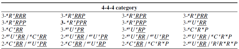
Some 2R1T RCM PMs in 4-4-4 category.

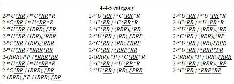
Some 2R1T RCM PMs in 4-4-5 category.

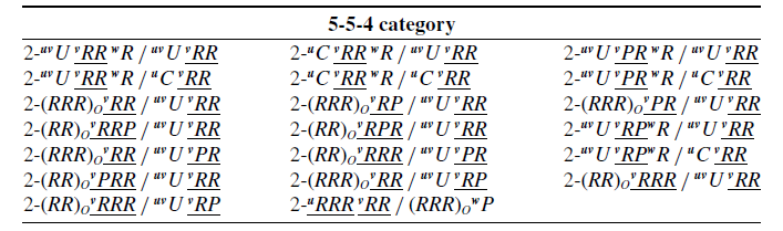
Some 2R1T RCM PMs in 5-5-4 category.

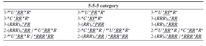
Some 2R1T RCM PMs in 5-5-5 category.

It should be noted that the structure of limbs does not necessarily have to be the same as in Table IV. Utilization of composite joints can simplify the configuration by minimizing the number of joints and links. When constructing mechanisms with these limbs, different choices can impact the redundancy of the mechanism. Redundant mechanisms offer enhanced load capacity and stiffness, whereas nonredundant mechanisms are characterized by their simpler structure and ease of control. Each type of mechanism is suited to specific applications based on these attributes.
3.3. Construction of 2R1T RCM PM
After having conducted the enumeration of mechanical generators of synthesized limb bonds, 2R1T RCM PM can be constructed with any three of them. In order to simplify the mechanism, at least two limbs should be chosen as the same, which means the topological structure should be either X-X-X or X-X-Y, where X and Y represent the DoF of the limb. According to this rule, there are four categories for all the configurations: 4-4-4, 4-4-5, 5-5-4, and 5-5-5. For conciseness, Tables V, VI, VII, and VIII enumerate some of the possible configurations for each category.
-
a. 4-4-4 category
PMs in this category are all redundant mechanisms. It turns out that all PMs in 4-4-4 category have only one translational DoF along the unit vector
w
. In these notations, two or three successive joints like
 $ \underline{{}^{\boldsymbol{v}}{R}{}RR}$
and
 $ \underline{{}^{\boldsymbol{v}}{R}{}R}$
mean these joints forming a planar motion unit, while (RR)O and (RRR)O mean a spherical motion unit.
3-
uv
U
 $ \underline{{}^{\boldsymbol{v}}{R}{}R}$
whose kinematic model is shown in Figure 6 is used as an example for illustration of this category. Since 2-
uv
U
 $ \underline{{}^{\boldsymbol{v}}{R}{}R}$
was synthesized by Li [Reference Li, Zhang, Müller and Wang22], 3-
uv
U
 $ \underline{{}^{\boldsymbol{v}}{R}{}R}$
has exactly the same properties.
The planes of motion denoted as
E
,
F
, and
G
are formed by each limb. Once the configuration is determined, the angles between the planes, denoted as
 $ \alpha,\ \beta,\ \textrm{and}\ \gamma$
, are determined accordingly. And A
i, B
i, C
i (i = 1, 2, 3) denote joints in the limb. The angular deflections of motion planes are defined as Ψ
1, Ψ
2, and Ψ
3 as in Figure 6. They have definite kinematic relationships expressed as the following equation [Reference Li, Zhang, Müller and Wang22], which indicates that the angular deflections Ψ
1, Ψ
2, and Ψ
3 are all coupled with each other.
 \begin{align} \left\{\begin{array}{l} \sin \psi _{1}\sin \psi _{2}+\cos \alpha \cos \psi _{1}\cos \psi _{2}=\cos \alpha \\[3pt] \sin \psi _{1}\sin \psi _{3}+\cos \beta \cos \psi _{1}\cos \psi _{3}=\cos \beta \\[3pt] \sin \psi _{2}\sin \psi _{3}+\cos \gamma \cos \psi _{2}\cos \psi _{3}=\cos \gamma \end{array}\right. \end{align}
Kinematic model of 3-
 ${}^{\boldsymbol{uv}}{U}{}\underline{{}^{v}{R}{}R}$
.

For the sake of illustration,
 $ \alpha, \beta$
, and
 $ \gamma$
are chosen to be the same value, which means
 $ \alpha = \beta = \gamma = 120^{\circ}$
. Thus, for Eq. (12), the solution is Ψ
1=Ψ
2=Ψ
3 = 0°. This means that the moving platform can only move along its normal direction with no rotational ability. Two configurations in this category are shown in Figure 7.
-
b. 4-4-5 category
Based on the analysis above, at most two 4-DoF limbs that can form a motion plane can be used when constructing 2R1T RCM PMs. If two such limbs are used, the mechanism has a bifurcated motion of 1R1T, which can be treated as a generalized 2R1T mechanism in its singular pose [Reference Refaat, Hervé, Nahavandi and Trinh47]. More details about bifurcation motion can be found in Ref. [Reference Li and Herve30] and [Reference Aimedee, Gogu, Dai, Bouzgarrou and Bouton48]. For there exist 9 different 4-DoF limbs and 32 different 5-DoF limbs in Table IV, a total of 288 PMs can be obtained by multiplying 9 by 32. All these mechanisms are redundant. Figure 8 shows six PMs in 4-4-5 category with bifurcation of 1R1T motion.
Two configurations in 4-4-4 category.

Six PMs in 4-4-5 category.

The circular dotted line around the end-effector in the limb indicates that this is a rotation around the center line of end-effector, that is, w R of the limb uv U v RR w R as in Figure 8(a). And the black diamond connected to the end-effect in the diagram indicates that it is a rigid connection.
-
c. 5-5-4 category
In contrast to 4-4-5 category with a bifurcation motion described above, 5-5-4 category is capable of continuous 2R1T motion in a whole workspace. For the seven limbs of {S2(O)}{G( v )}, they can be combined with all nine 4-DoF limbs. And for the 10 limbs of {S(O)}{G-1( v )} and {R(O, u )} {G( v )}{R(O, w )}, they can be combined with the 8 4-DoF limbs, except for the one of {S(O)}{T( w )}. Finally, for the 15 limbs of {G( u )}{G-1( v )}, they can only be combined with the 1 limb of {S(O)}{T( w )}. Therefore, a total of 7 × 9 + 10 × 8 + 15 × 1 = 158 PMs can be obtained in this category, and they are redundant mechanisms.
Six PMs in 5-5-4 category.

Similarly, Figure 9 shows six PMs in 5-5-4 category, where 2- uv U v RR w R/ uv U v RR and 2- uv U v PR w R/ uv U v PR have been presented [Reference Yaşır, Kiper and Dede25, Reference Zhang, Yu and Du49]. PMs in this category have a higher potential for practical application due to their continuous motion.
-
d. 5-5-5 category
Though PMs in 5-5-5 category are non-overconstrained mechanisms compared with the previous, there exists a local rotation around the end-effector in some 5-5-5 PMs, which means a movable motor is required to control this rotation [Reference Li, Herve and Huang5] or it can be eliminated by using a helical joint. Mechanisms with such local rotation are indicated with a subscript (*) in Table VIII, and Figure 10 shows six 2R1T RCM PMs in 5-5-5 category.
Six 2R1T RCM PMs in 5-5-5 category.

4. Type synthesis of the primary PM
By the type synthesis of the secondary 2R1T RCM PM, the RCM is found to be the intersection of the axes of the first rotation joint in each limb, in order to realize the motion of RCM, double-stage PM can be constructed by adding the first-level PM, that is, the primary PM. The motion based on RCM remains unchanged with respect to the first-level moving platform.
Depending on the dimension of the translation for RCM, the primary PM can be classified into three categories: 1T, 2T, and 3T. Similarly, in order to achieve maximum isotropy and facilitate the modular assembly of the secondary PM, the primary PM should have three identical limb chains with a minimum number of joints as far as possible.
4.1. Primary PMs with 1T motion
Only PM with {T( w )} motion is synthesized here for convenience. The easiest way to achieve the target motion {T( w )} is to use three parallel P joints to build an original PM as shown in Figure 11(a). With the concept of configuration evolution, the limb bond can evolve into 2-D and 3-D limbs in Figure 11(b).
Using the evolved 3-D limb generating {G( v )}, which is an RPR limb in Figure 11(b), can construct the primary PMs with the target motion 1T that can be proved as follows:
 \begin{align} M_{PM}=\overset{3}{\underset{i=1}\cap }M_{Li}=\overset{3}{\underset{i=1}\cap }\left\{R\left(O,v_{i}\right)\right\}\left\{T\left({\boldsymbol{w}}\right)\right\}\left\{R\left(A,v_{i}\right)\right\}=\overset{3}{\underset{i=1}\cap }\left\{G\left({\boldsymbol{v}}_{i}\right)\right\}=\left\{T\left({\boldsymbol{w}}\right)\right\} \end{align}
As discussed in subsection 3.3, PMs listed in Table V can achieve the target motion, and the limbs generating {R(O, v )}{G( v )} can degenerate into the 3-D limb generating {G( v )} in Figure 9(b) by the removal of the rotation in the first U joint. A total of four configurations can be obtained in this way, and they are sketched in Figure 12.
Original PM 3- w P and its evolution of limb chains.

Four primary PMs with 1T motion.

4.2. Primary PMs with 2T motion
For 2T motion, {T( u )}{T( v )} is chosen as the target motion to be synthesized, and an original PM can be obtained as in Figure 13. Similarly, {T( u )}{T( v )} can evolve into {G( w )} by adding a rotation around w -axis. It is easy to obtain PMs that can achieve the target motion using the limb bond {G( w )}.
Original PM 3- w PP .

Four PMs obtained are shown in Figure 14, where Figure 14(a) is a planar mechanism that has been studied in depth [Reference Wu, Wang and Wang50, Reference Wang, Xie, Li and Bai51]. However, it is worth noting that these PMs have a rotation around the w -axis, which is actually an unexpected motion. This may provide greater flexibility to these mechanisms, but on the other hand, the existence of such a motion likewise poses a potential problem in that this rotation may be unwanted during surgery.
In order to eliminate the rotation, it is feasible to evolve two successive R joints, RR, into a parallelogram (Pa) joint, for the parallelogram joint allows the output link to remain in a fixed orientation with respect to the input link [Reference Liu and Wang11].
Four primary PMs with 2T motion.

4.3. Primary PMs with 3T motion
A serial chain consisting of three independent P joints can accomplish 3T motion in space, but higher stiffness and accuracy can be achieved by using a PM. To endow 3T motion to the moving platform, {T( u )}{T( v )}{T( w )} should be included in the limb bond. An original PM as shown in Figure 15 can be evolved from 3- w PP in Figure 13.
Original PM 3- wPP wP.

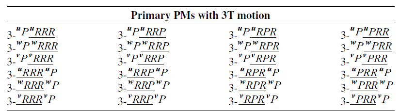
The 3-D limb bond {T( u )}{T( v )}{T( w )} can evolve into 4-D limb bonds in Eq. (13). Among these limb bonds, the forms that allow the arrangement of fixed P joint are preferable. All configurations that have one P joint at most in their single limb are listed in Table IX.
Primary PMs with 3T motion.

 \begin{align} \left\{T\left({\boldsymbol{u}}\right)\right\}\left\{T\left({\boldsymbol{v}}\right)\right\}\left\{T\left({\boldsymbol{w}}\right)\right\}=\left\{\begin{array}{l} \left\{T\left({\boldsymbol{u}}\right)\right\}\left\{G\left({\boldsymbol{u}}\right)\right\}\text{ or }\left\{G\left({\boldsymbol{u}}\right)\right\}\left\{T\left({\boldsymbol{u}}\right)\right\}\\[3pt] \left\{T\left({\boldsymbol{w}}\right)\right\}\left\{G\left({\boldsymbol{w}}\right)\right\}\text{ or }\left\{G\left({\boldsymbol{w}}\right)\right\}\left\{T\left({\boldsymbol{w}}\right)\right\}\\[3pt] \left\{T\left({\boldsymbol{v}}\right)\right\}\left\{G\left({\boldsymbol{v}}\right)\right\}\text{ or }\left\{G\left({\boldsymbol{v}}\right)\right\}\left\{T\left({\boldsymbol{v}}\right)\right\} \end{array}\right. \end{align}
Figure 16 shows three typical configurations with fixed P joints. With this design, the obtained PMs can have reduced moving mass, higher rigidity, and simpler kinematic model [Reference Gan, Dai, Dias and Seneviratne52].
Three typical 3T PMs with fixed P joints.

5. Construction of double-stage PMs with movable RCM
For consideration of practicality, RCM PMs in 4-4-5 category are excluded in the following part due to the existence of a bifurcation motion. During the construction of double-stage PMs with movable RCM, 2- uv U v RR w R/ uv U v RR is used as a representative of the secondary PMs.
5.1. Design of connection styles
The design of the connection style between the two stages should be based on the geometrical conditions of the secondary PM, for the primary PM should maintain the 2R1T RCM motion at all times. Geometrical conditions for the secondary PM with 2R1T RCM motion can be concluded as follows:
(1) The axis of the first rotation in each limb should intersect with each other at RCM.
(2) At most two limbs whose kinematic bond including 3-D subgroup {S(O)} can be used.
(3) The motion planes generated by limbs have to intersect along a straight line, while RCM belongs to the foregoing line.
(4) The motion planes generated by limbs cannot coincide.
It is easy to use a rigid connection as in Figure 17(a) to realize the construction, which is defined as connection style I. The end-effector of the secondary PM, ED2 in Figure 17(a), is fixedly attached to the end-effector of the primary PM to use it as a base, which means the kinematic configuration of the secondary PM will not be affected by the motion of the primary PM. Configurations employing this connection style can be seen as a “Parallel + Parallel” type hybrid PM [Reference Cao, Zhou, Qin, Liu, Ji and Zhang53]. The motion of the primary PM only realizes the motion of RCM without breaking the required geometrical conditions of the secondary PM. As opposed to the above connection style, another connection style shown in Figure 17(b) allows for higher flexibility due to the possible adjustment. The connectivity can be chosen as either a P joint or an R joint as long as it can maintain the geometrical conditions above. But here, only the P joint is suitable for the design because the feasible limbs are characterized by the fact that the first joint is an R joint or a C joint and using a R joint results in two coaxial rotations, leading to redundant joints, which is unexpected.
This connection imposes higher demands on assembly precision because the limbs and motion pairs of the two-level platforms become coupled. Compared to connection style I, the motion of the primary platform in the second type can affect the configuration of the second-level platform. Therefore, when controlling the first-level platform, it is necessary to simultaneously consider the second-level platform. However, connection style II also provides the mechanism with greater flexibility and adaptability as it creates specific kinematics and workspace of the secondary PM.
Topological structure of two connection styles.

Some double-stage PMs with 1T-RCM and 2T-RCM in connection style I. (a) (3- v PRR )-E-(2- uv U v RR w R/ uv U v RR ), (b) (3- v RPR )-E-(2- uv U v RR w R/ uv U v RR ), (c) (3- v RRP )-E-(2- uv U v RR w R/ uv U v RR ), (d) (3- v RRR )-E-(2- uv U v RR w R/ uv U v RR ), (e) (3- w PRR )-E-(2- uv U v RR w R/ uv U v RR ), (f) (3- w RPR )-E-(2- uv U v RR w R/ uv U v RR ), (g) (3- w RRP )-E-(2- uv U v RR w R/ uv U v RR ), (h) (3- w RRR )-E-(2- uv U v RR w R/ uv U v RR ).

The double-stage PMs with movable RCM employing the two connection styles are denoted as “(PM1)-E-(PM2)” and “(PM1)-P-(PM2),” where “E” means a rigid connection between the two stages while “P” denotes using a prismatic joint as the connectivity between the two stages.
5.2. Connection style I
By combining RCM PMs in Section 3 and PMs synthesized in Section 4, several double-stage PMs with movable RCM can be built through different combinations. Figures 18 and 19 show some double-stage PMs in connection style I using a rigid connection between the two stages. In Figure 18, the primary PM of the former four PMs actually has the same limb structure as the latter four PMs but employing different assembly relationships.
Figure 20 shows the configuration with 2T-RCM whose undesired rotation is eliminated by using the Pa joint. It is worth noting this configuration can be further evolved into a 3T Delta-like mechanism shown in Figure 21, which features high speed and acceleration properties by adding R joint to limbs, and this indicates higher potential for practical applications.
Some double-stage PMs with 3T-RCM in connection style I. (a) (3- u P u PRR )-E-(2- uv U v RR w R/ uv U v RR ), (b) (3- u P u RPR )-E-(2- uv U v RR w R/ uv U v RR ), (c) (3- u P u RRP )-E-(2- uv U v RR w R/ uv U v RR ), (d) (3- u P u RRR )-E-(2- uv U v RR w R/ uv U v RR ), (e) (3- v P v PRR )-E-(2- uv U v RR w R/ uv U v RR ), (f) (3- v P v RPR )-E-(2- uv U v RR w R/ uv U v RR ), (g) (3- v P v RRP )-E-(2- uv U v RR w R/ uv U v RR ), (h) (3- v P v RRR )-E-(2- uv U v RR w R/ uv U v RR ), (i) (3- w P w PRR )-E-(2- uv U v RR w R/ uv U v RR ), (j) (3- w P w RPR )-E-(2- uv U v RR w R/ uv U v RR ), (k) (3- w P w RRP )-E-(2- uv U v RR w R/ uv U v RR ), (l) (3- w P w RRR )-E-(2- uv U v RR w R/ uv U v RR ).

2T-RCM configuration without undesired rotation.

3T-RCM configuration with a Delta-like primary PM.

Some double-stage PMs in connection style II. (a) (3- v PRR )-P-(2- uv U v RR w R/ uv U v RR ), (b) (3- v RPR )-P-(2- uv U v RR w R/ uv U v RR ), (c) (3- v RRP )-P-(2- uv U v RR w R/ uv U v RR ), (d) (3- v RRR )-P-(2- uv U v RR w R/ uv U v RR ), (e) (3- w RRR )-P-(2- uv U v RR w R/ uv U v RR ), (f) (3- u P u PRR )-P-(2- uv U v RR w R/ uv U v RR ), (g) (3- u P u RPR )-P-(2- uv U v RR w R/ uv U v RR ), (h) (3- u P u RRP )-P-(2- uv U v RR w R/ uv U v RR ), (i) (3- u P u RRR )-P-(2- uv U v RR w R/ uv U v RR ), (j) (3- v P v RRP )-P-(2- uv U v RR w R/ uv U v RR ), (k) (3- w P w RRP )-P-(2- uv U v RR w R/ uv U v RR ).

Illustration of the infeasibility.

Three configurations of the secondary PM.

5.3. Connection style II
More double-stage PMs with movable RCM can be obtained based on connection styles II by choosing different primary PMs and secondary PMs. Figure 22 shows some double-stage PMs in connection style II. It is important to note that connection style II provides the mechanism with greater flexibility and adaptability.
When utilizing connection style II, it is crucial to preserve the motion based on the RCM. This implies maintaining the assembly relationship of the limb chains in the secondary PM. However, certain primary PMs are not capable of meeting these requirements consistently after movement, rendering them unsuitable for this type of connection. Figure 23 illustrates the infeasibility of connection style II in some configurations that takes 3- v P v PRR -P-2- uv U v RR w R/ uv U v RR as a representative.
As the configuration 3- v P v PRR -P-2- uv U v RR w R/ uv U v RR shown in Figure 23, the first rotation axis of the three U joints in the secondary PM intersects with each other at the RCM when it is at the initial position in Figure 22(a). After a finite displacement of joints as indicated by the orange arrow in Figure 22(b), the three axes cannot always intersect at RCM, which means the geometrical condition (1) is damaged.
As mentioned above, connection style II provides higher flexibility and adaptability for the configuration due to both the motion of the P joint used as the connectivity and the primary platform that can influence the configuration of the secondary platform, thus affecting its kinematics and workspace. Figure 24(a) shows the initial posture of the mechanism. The orange dotted line indicates the close-loop formed by a limb and the end-effector of the secondary PM. Figure 24(b) represents the change of the geometrical relationship within the closed loop after the finite motion of the P joint as shown by the red arrows. Similarly, Figure 24(c) shows the effect of the motion of the primary PM, which is indicated by the red arrows. It is obvious that specific kinematics can be obtained by adjustment of the connectivity joint or the motion of the primary PM, which means the performance and corresponding workspace can be different. This indicates the flexibility and adaptability of double-stage PMs in this connection style.
6. Conclusion
In this paper, the double-stage topological structure is utilized to realize the adjustment of RCM, which provides the RCM PM with greater flexibility. A family of double-stage PMs with movable RCM is designed using configuration evolution based on Lie-group. All feasible limb bonds for 2R1T RCM motion are systematically synthesized, and all possible limbs for the secondary PM are enumerated accordingly. Primary PMs that realize the positioning of RCM are synthesized based on the proposed method. Different connection styles are designed and subjected to a comparative analysis. Applying different connection styles based on the geometrical conditions, a new family of double-stage PMs with movable RCM is constructed. The concept of double-stage PM can also be employed to design other specific mechanisms. It should be noted that further comparisons between these feasible configurations and dimensional synthesis for practical application are needed to achieve optimal performance.
Author contributions
Xianhai Lv: conceptualization, methodology, visualization, writing. Fan Ye: data curation, validation. Kai Wang: writing – review and editing. Hao Sun: visualization. Yi Cao: supervision, writing – review and editing.
Financial support
This research received no specific grant from any funding agency, commercial, or not-for-profit sectors.
Competing interests
The authors declare no conflicts of interest exist.
Ethical approval
Not applicable.