Introduction
The Internet of Things (IoT) is a new technology that connects a variety of physical objects, machines, sensors, servers, other devices, and people through communication networks [1]. This new technology is expected to make human life more productive, safe, healthy, and comfortable by solving numerous challenges related to the environment, energy, urbanization, industry, and logistics [Reference Kafle, Fukushima and Harai2]. It can be deployed in many fields, including smart homes (e.g. security, heating, and lighting control), smart cities (e.g. waste management system), healthcare (e.g. remote patient monitoring), smart manufacturing (e.g. remote monitoring and control of manufacturing system), and agriculture [Reference Shin and Kwon3–Reference Liu, Liu, Zeng and Ma5]. For this reason, IoT is considered as one of the key technologies to globally improve the quality of life, economic growth, and employment, with the European Union market value expected to exceed one trillion Euros in 2020 [Reference Vukobratovic, Jakovetic, Skachek, Bajovic, Sejdinovic, Kurt, Hollanti and Fischer6].
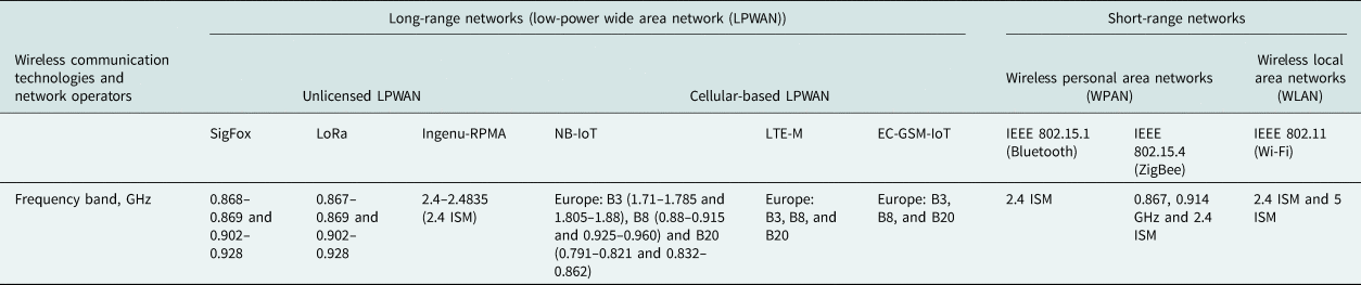
Several communication technologies and frequency bands have been identified for IoT applications, as listed in Table 1. Generally, the range of frequencies associated with IoT applications covers the band between 0.8 and 2.5 GHz. Due to this reason, there is an increasing demand for broadband or multiband antennas for IoT devices. One advantage of using broadband antennas is that they enable the same antenna to support many wireless standards and applications, which reduces the overall system size/weight [Reference Kashkool, Yahya, Al-Rizzo and Al-Wahhamy7]. Moreover, antennas for IoT applications need to be flexible and robust because they operate in environments subjected to shape deformation. The antennas for IoT devices also need to be low profile, light-weight, and with high radiation efficiency to facilitate the energy efficiency of the devices.
Wireless communication technologies and frequency bands for IoT applications

Recently, several antenna designs have been investigated for their suitability as antennas for IoT devices. Some of these designs include patch antennas [Reference Birwal, Singh, Kanaujia and Kumar8–Reference Jha, Bukhari, Singh, Mishra and Sharma10], planar monopole antennas [Reference Bashir, Jha, Mishra, Singh and Sharma11], printed inverted-F antennas [Reference Cheung, Yuen and Mung12], and loop antennas [Reference Damis, Khalid, Mirzavand, Chung and Mousavi13]. In most of these publications [Reference Shafique, Khawaja, Khurram, Sibtain, Siddiqui, Mustaqim, Chattha and Yang9–Reference Bashir, Jha, Mishra, Singh and Sharma11, Reference Damis, Khalid, Mirzavand, Chung and Mousavi13], however, fractional bandwidths (FBW = ((fH–fL)/fC) × 100%, where fL and fH are the lowest and highest usable frequency of the antenna for |S 11| ≤ −10 dB, respectively, and fC is the center frequency of the operation band) are generally <50%. Also, most of the above-mentioned antennas except [Reference Damis, Khalid, Mirzavand, Chung and Mousavi13] have been designed on rigid substrates such as FR4 [Reference Birwal, Singh, Kanaujia and Kumar8–Reference Jha, Bukhari, Singh, Mishra and Sharma10, Reference Cheung, Yuen and Mung12] and polyguide substrates [Reference Bashir, Jha, Mishra, Singh and Sharma11]. However, different types of flexible materials such as liquid crystalline polymer [Reference Zahran, Abdalla and Gaafar14], poly-dimethyl-syloxane [Reference Damis, Khalid, Mirzavand, Chung and Mousavi13], rubber [Reference Al-Sehemi, Al-Ghamdi, Dishovsky, Atanasov and Atanasova15], rubber-textile composites [Reference Al-Sehemi, Al-Ghamdi, Dishovsky, Atanasov and Atanasova16], and textile [Reference Atanasov, Atanasova, Stefanov and Nedialkov17] have been widely used in the current designs of flexible antennas.
The novelty in our work lies in the fact that we designed and experimentally realized a flexible light-weight and high-efficiency broadband antenna with a fractional bandwidth of 98% that covers the most commonly used wireless communication standards and technologies for IoT applications including the SigFox (0.868–0.869 GHz and 0.902–0.928 GHz), LoRa (0.867–0.869 GHz and 0.902–0.928 GHz), Ingenu-RPMA (2.4–2.4835 GHz), NB-IoT, LTE-M (B3, B8, and B20), ZigBee (0.867, 0.914 GHz), and Bluetooth (2.4–2.4835 GHz) as presented in Table 1. Attention is focused on introducing new structural designs for the antenna elements and the inclusion of a rubber composite as the antenna's substrate for a relatively easy realization of flexible and mechanically robust antenna for IoT applications.
Antenna design
Antenna configuration
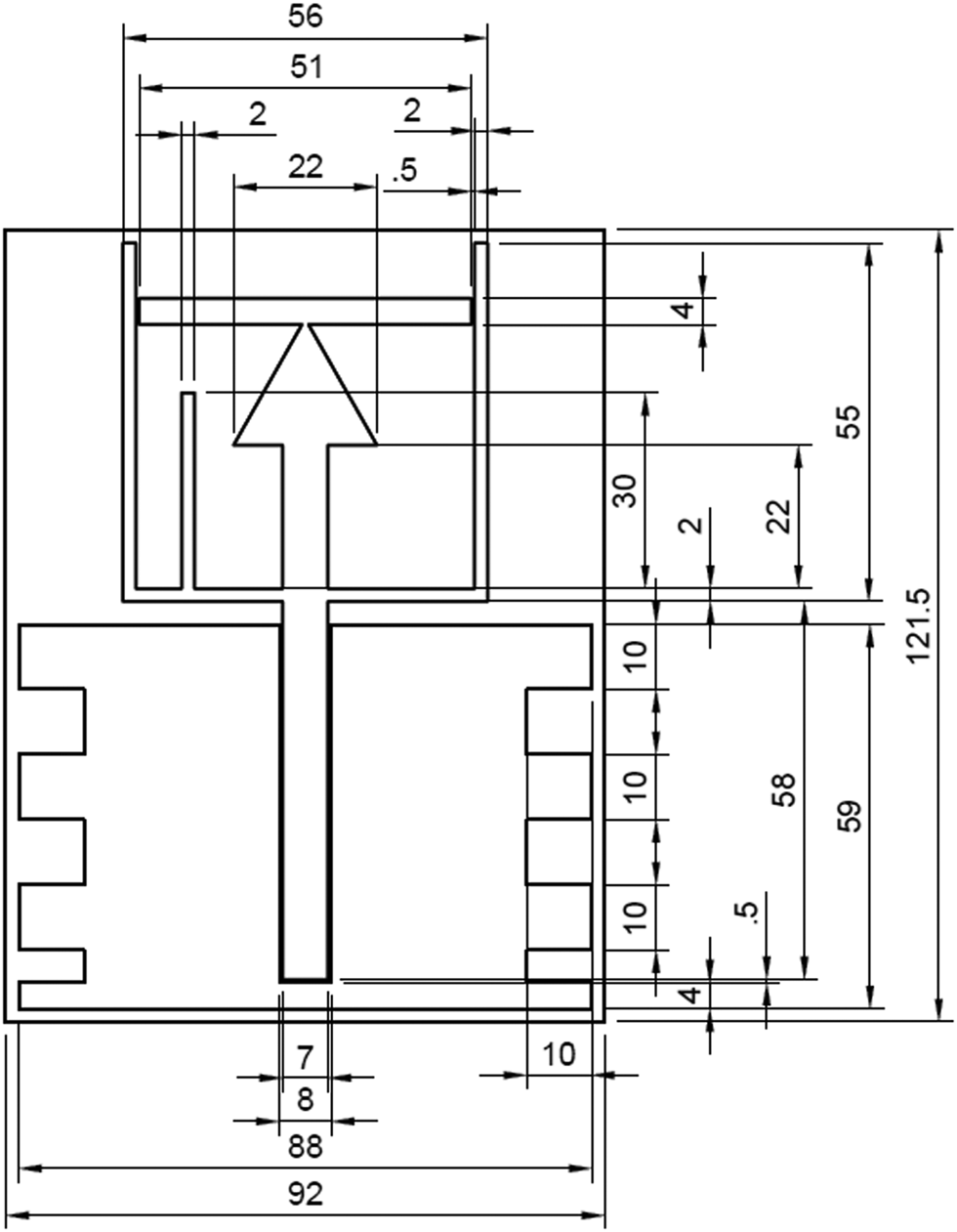
The configuration of the proposed antenna is shown in Fig. 1. The antenna design is based on a U-shaped and triangular-shaped radiator with two tuning stubs. A 50 Ω coplanar waveguide (CPW) transmission line is employed to feed the antenna. CPW feeding is preferred here over the microstrip line since no via holes or shorting pins [Reference Mandal, Karmakar, Singh, Mandal, Mahapatra and Mal18] and allows to keep the antenna as flexible and thin as possible. The antenna design and optimization are performed by using xFDTD (xFDTD, Remcom Inc., State College, PA, USA), a finite-difference time-domain method (FDTD)-based simulation software. From the simulation studies, the overall size of the antenna, including the CPW feed line, is found to be 0.26 λ 0 × 0.32 λ 0 × 0.006 λ 0, where λ 0 is the free space wavelength at 0.856 GHz (92 mm × 121.5 mm × 2 mm).
Configuration of the proposed flexible broadband antenna with optimized dimensions and a thickness of 2 mm. All dimensions are in mm.

Antenna design process
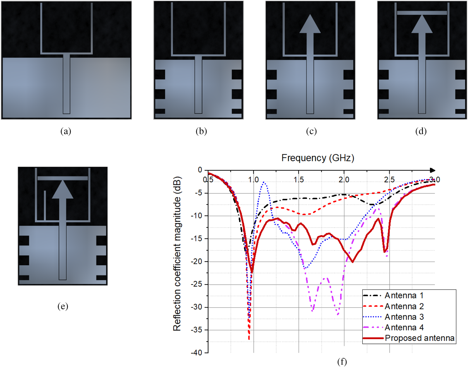
The design process steps and corresponding simulated reflection coefficient magnitude (|S 11|) curves are presented in Fig. 2.
Design steps of the proposed antenna: (a) Antenna 1, (b) Antenna 2, (c) Antenna 3, (d) Antenna 4, (e) proposed antenna, and (f) simulated |S 11| curves versus frequency for the different design modification steps.

During the first step of the design process, a CPW-fed U-shaped monopole antenna is designed (Antenna 1 in Fig. 2(a)) to obtain resonance at 0.919 GHz. It is observed that Antenna 1 (see Fig. 2(f)) exhibits an |S 11| ≤ −10 dB band from 0.84 to 1.046 GHz, i.e. around 22% fractional bandwidth. Next, we apply several techniques described below to broaden the bandwidth of the antenna. Firstly, the ground plane is modified by cutting rectangular-shaped slots as shown in Fig. 2(b) (Antenna 2). A broader bandwidth (|S 11| ≤ −10 dB) of 25% from 0.86 to 1.109 GHz is observed. In the next step, a triangular monopole is included (Antenna 3 in Fig. 2(c)). Incorporation of the triangular monopole leads to a second resonant frequency at 1.585 GHz and a relatively large impedance bandwidth from 1.204 to 2.234 GHz (Antenna 3 in Fig. 2(f)). A horizontal stub is added to the triangular monopole (Antenna 4 in Fig. 2(d)) to increase the bandwidth further. This modification results in further improvement of impedance matching and effective merging of two resonances at 0.919 and 1.585 GHz. Finally, in the fifth step, a vertical stub is included in the proposed antenna to achieve an impedance bandwidth of 0.856–2.513 GHz, which covers the most commonly used wireless communication standards and technologies for IoT applications. Compared to Antenna 1, the fractional bandwidth of the proposed antenna increases from 22 to 98%, respectively.
The geometrical dimensions and position of the antenna's elements were tuned to achieve the optimal impedance matching and high radiation efficiency at the targeted band from 0.867 to 2.5 GHz.
Fabrication process
Materials
For flexibility, the substrate of the proposed antenna is fabricated from a flexible composite synthesized by mixing natural rubber with SiO2 as a filler. The major advantage of using rubber-based composite among all available flexible materials lies in its good electromagnetic (low permittivity and loss tangent), mechanical (thermal stability, flexibility, and strength), and chemical (hydrophobic) properties. The low production cost is also an added advantage for the rubber composite [Reference Al-Sehemi, Al-Ghamdi, Dishovsky, Atanasov and Atanasova16].
The composition of the composite in phr (parts per 100 parts of rubber) is as follows: natural rubber STR 10 – 100.0, zinc oxide – 3.0, stearic acid – 2.0, isopropyl-phenyl-p-phenylenediamine – 1.0, N-tert-butyl-benzothiazole-sulfenamide – 1.5, sulfur – 2.0, and SiO2 – 30.0 as a filler. The composite was prepared on an open laboratory two rolls mill and then was vulcanized to form a plate with dimensions 150 mm × 150 mm × 2 mm.
After the vulcanization, the electromagnetic parameters of the composite were measured by the resonant perturbation method. The real part of the complex relative permittivity $\lpar {\varepsilon_r^{\prime} } \rpar$ was 2.503 and imaginary $\lpar {\varepsilon_r^{^{\prime\prime}} } \rpar$
 part was 0.039, respectively. The tangent of the dielectric loss angle was also obtained – 0.015. The results were verified with the measurement of the electromagnetic parameters of standard material polytetrafluoroethylene. The measured values of $\varepsilon _r^{\prime}$
 and $\varepsilon _r^{^{\prime\prime}}$
 were used in the numerical model of the antenna (for the substrate) during the steps of the design process described in section ‘Antenna design’.
The radiating elements, along with the CPW, are built using a highly conductive woven fabric P1168 (supplied by Adafruit, Italy) with a thickness of 0.08 mm. The fabric consists of woven mesh polyester fibers coated with copper and nickel. The sheet resistance Rs is 0.05 Ω/sq. The information about the fabric was gathered from the datasheet provided by the manufacturer.
Prototype fabrication
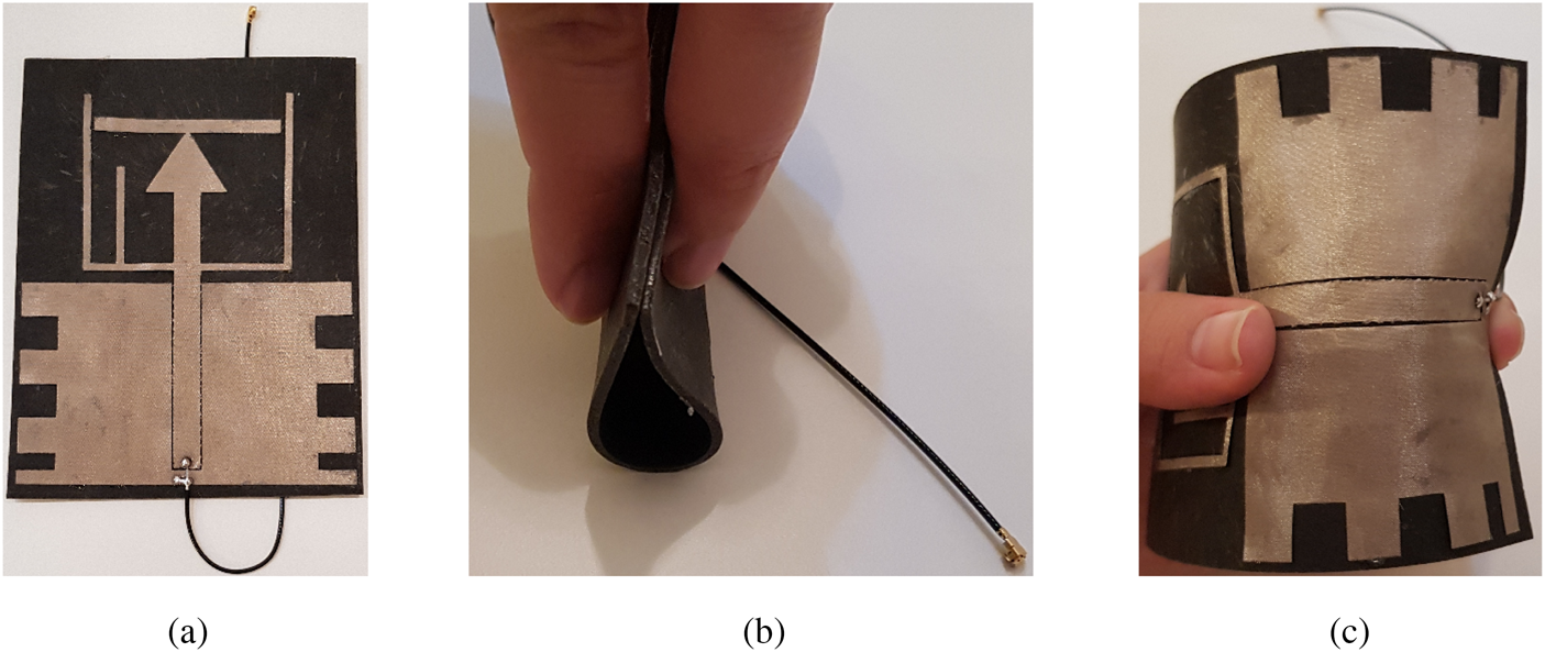
The antenna was fabricated by a cost-effective and time-saving fabrication technique. First, the radiating elements, along with the CPW, were directly shaped on the conductive fabric with a cutting plotter and then attached to the substrate using glue. A coaxial cable with a U. FL connector was soldered to the CPW for measurement purposes. Photographs of the fabricated antenna are shown in Fig. 3.
Photographs of the fabricated prototype: (a) top view, (b) side view of the bended antenna, and (c) top view of the bended antenna.

Results and discussion
S-parameter and flexibility test
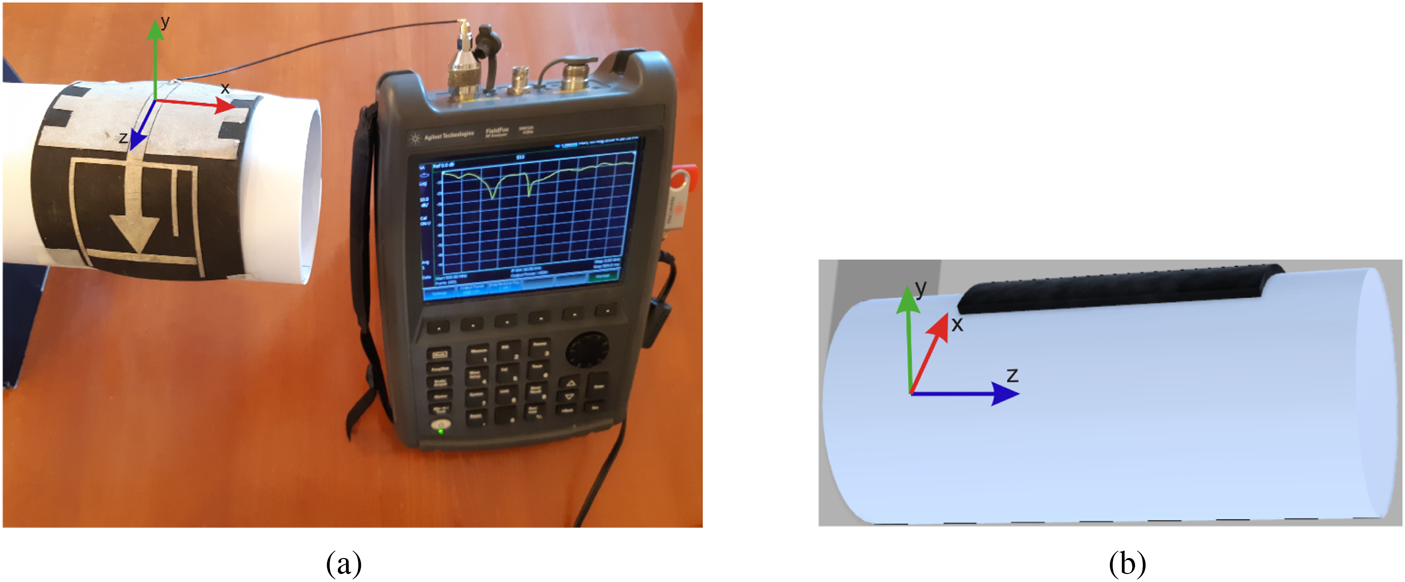
In this section, a study of the reflection coefficient characteristics under different degrees of structural deformation is presented. Figure 4 shows the flexibility test setup where the fabricated prototype is bent over a paper cylinder having a radius of 45 mm and connected to a network analyzer (FieldFox N9912A, Agilent, Santa Rosa, CA, USA) for S-parameter measurements. The bending is applied to the proposed antenna in two directions: along the x- and z-axis. Also, the |S 11| and bandwidth are evaluated when the prototype is bent over paper cylinders having a radius of 25, 35, 55, and 65 mm, respectively.
Flexibility test setup: (a) bending is applied along the x-axis and (b) bending is applied along the z-axis.

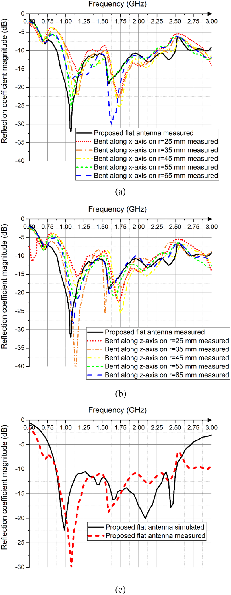
The measured reflection coefficient characteristics of the prototype antenna under flat and bent conditions are depicted in Fig. 5. As it can be seen, the |S 11| curves of the antenna bent along x- and z-axis follow a similar trend as that of the flat antenna. A small shift in the first resonant frequency (about 8% when the antenna is bent along the x- and z-axis over a paper cylinder having a radius of 25 mm) could be observed.
Measured reflection coefficient magnitude curves versus frequency when the proposed antenna is bent on paper cylinders and when it is flat. The bending is applied to the proposed antenna in two directions: (a) along the x-axis, (b) along the z-axis, and (c) comparison of measured and simulated results for the proposed flat antenna.

From the presented results, it can also be observed that antenna bandwidth does not show any detectable change to bending. Hence, we conclude that bending has a minor effect on the antenna impedance matching for both directions of bending. Figure 5(c) also shows the comparison of measured and simulated |S 11| curves versus frequency for the proposed flat antenna. A good agreement is obtained between measurements and simulations in terms of the −10 dB bandwidth. The small difference in the |S 11| curves between the measured and the simulated results is primarily attributed to fabrication and assembly inaccuracies. Moreover, the coaxial cable and U. FL connector were not integrated into the FDTD simulations, which also lead to a difference between the measurements and simulations.
Surface current distributions
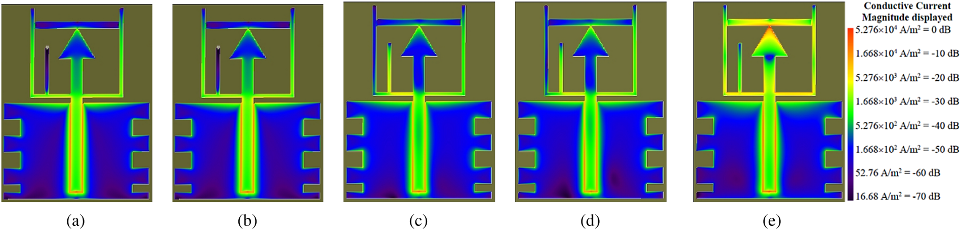
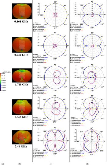
In Fig. 6, the simulated surface current distributions on the proposed antenna at 0.868, 0.942, 1.748, 1.843, and 2.44 GHz are illustrated. As we can see, at 0.868 and 0.942 GHz, the surface current is flowing at the perimeter of the antenna (on the U-shaped monopole) and on the triangular monopole. At 1.748 and 1.843 GHz, the surface current on the triangular monopole and vertical stub increases while the current density is low at the half of the U-shaped monopole. With further increase of the operating frequency to 2.44 GHz, the surface current on the horizontal stub increases and also significantly contributes to the radiation mechanism.
Simulated surface current distributions at: (a) 0.868 GHz, (b) 0.942 GHz, (c) 1.748 GHz, (d) 1.843 GHz, and (e) 2.44 GHz.

Radiation patterns
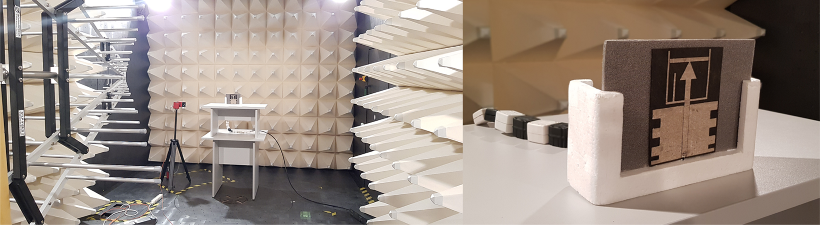
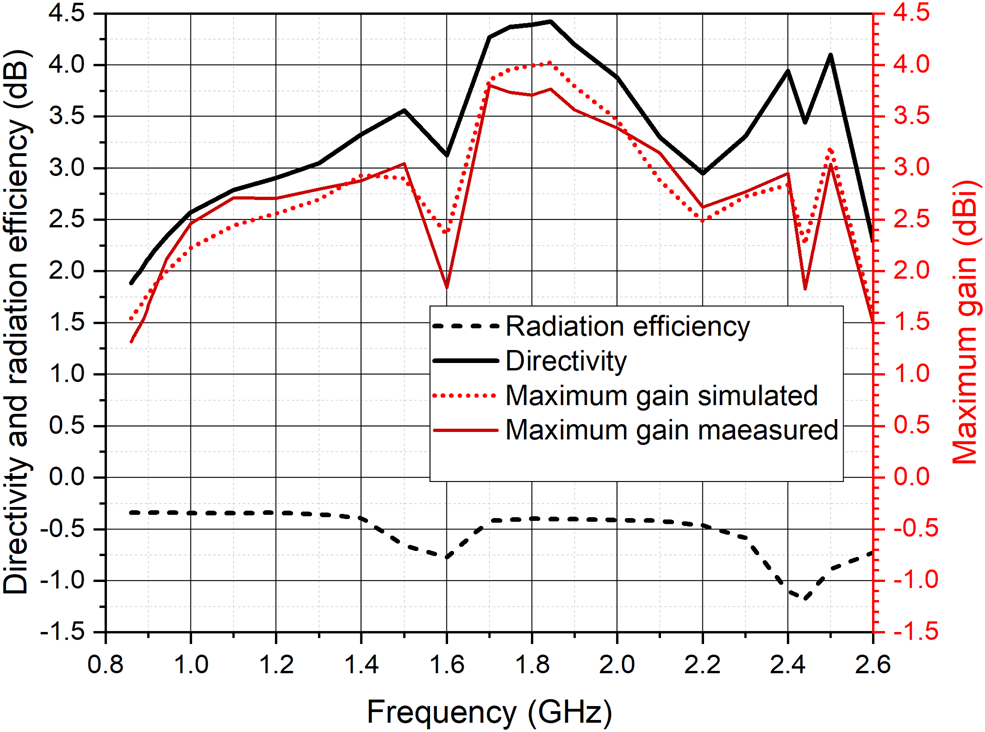
The radiation patterns in the xy- and yz-plane were measured inside a semi-anechoic chamber (Fig. 7). Figure 8 shows the comparison between measurement and simulation radiation patterns at 0.868, 0.942, 1.748, 1.843, and 2.44 GHz. A good agreement is obtained between both. The results also show that at 0.868 and 0.942 GHz, the proposed antenna has an omnidirectional pattern in the xy-plane and a dipole-like pattern in the yz-plane. Moreover, it can be observed that Eθ is the dominant field component at 0.868, 0.942, 1.748, and 1.843 GHz for the antenna. At 2.44 GHz, Eφ is the dominant field component for this antenna. At this frequency, the radiation pattern of the antenna is dominated by the currents formed along with the horizontal stub, U-shaped and triangular-shaped monopoles (Fig. 6 (e)). As we can see from Fig. 9, the maximum gain of the antenna dropped from 2.9 dBi (at 2.4 GHz) to about 1.8 dBi (at 2.44 GHz) because more energy is radiated in φ direction. Moreover, the radiation performance of the antenna at 2.44 GHz provides a satisfactory radiation efficiency of −1.25 dB, which is proper for most of the IoT applications.
Radiation pattern measurement setup inside a semi-anechoic chamber.

Radiation patterns of the proposed antenna: (a) scale of the antenna gain, (b) simulated 3D, (c) simulated and measured normalized 2D in the xy-plane, and (d) simulated and measured normalized 2D in the yz-plane.

Simulated directivity, radiation efficiency, maximum gain, and measured maximum gain of the proposed antenna.

Directivity, radiation efficiency, and gain
The simulated directivity, radiation efficiency, and maximum gain are plotted in Fig. 9. It can be observed that the simulated radiation efficiency is quite stable in the frequency range from 0.868 to 1.4 GHz (between −0.39 and −0.34 dB, i.e. 91.4 and 92.5%, respectively) and from 1.7 to 2.2 GHz (between −0.39 and −0.46 dB, i.e. 91 and 90%, respectively), while the maximum gain varies. A reduction in gain and radiation efficiency is observed in the frequency range from 1.4 to 1.6 GHz. The variation in the gain values is related to the directivity of the antenna because the antenna gain is a product of radiation efficiency and directivity [Reference Chen, Liu, Nakano, Qing and Zwick19]. The directivity is solely determined by the radiation pattern of the antenna [Reference Stutzman and Thiele20]. As shown in Fig. 8, the shape of the antenna pattern changes as the frequency is increased. The radiation pattern exhibits very low directivity, as shown in Fig. 9, and resembles isotropic at 0.868 and 0.942 GHz, where the maximum gain is 1.5 and 2 dBi, respectively. The directivity of the radiation pattern increases at 1.843 GHz providing the antenna peak gain from about 4 dBi. However, it should be noted that the radiation efficiency (power radiated into space divided by total power (radiated power plus material losses) into the antenna) is <0 dB (100%) due to the power absorbed at the rubber composite substrate.
Figure 9 also shows the measured maximum gain of the antenna in the frequency range of 0.86–2.6 GHz. A good agreement between the simulated and measured gain can be observed.
Effect of change in substrate material properties
Under practical circumstances, the antennas for IoT applications may be exposed to various types of environments for a long duration, which may lead to a change in the antenna substrate material properties, e.g. the permittivity, which might then affect the performance of the wearable antenna [Reference Hall and Hao21]. To investigate the robustness of the proposed design, a ±20% variation was introduced in $\varepsilon _r^{\prime}$ and $\varepsilon _r^{^{\prime\prime}}$
 of the substrate. First, $\varepsilon _r^{\prime}$
 changes up to ±20% with respect to the measured value ($\varepsilon _r^{\prime} =$
 2.503) of the rubber composite used in the substrate of the proposed antenna are investigated. All parameters of the flexible antenna are kept the same and only $\varepsilon _r^{\prime}$
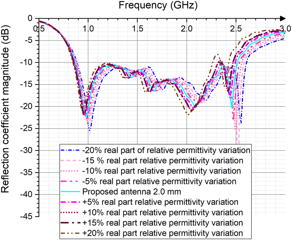
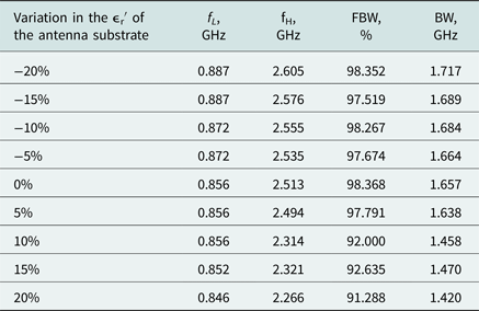
 is varied during the simulations (parametric study). From the simulation results, the lowest usable frequency (fL), the highest usable frequency (fH), and the bandwidth (BW) of the antenna for |S 11| ≤ −10 dB are recorded and shown in Table 2 and Fig. 10. As expected, fL, fH, and bandwidth decrease with increasing $\varepsilon _r^{\rm ^{\prime}}$
 of the substrate. Moreover, $\varepsilon _r^{\prime}$
 of the substrate material also affects the bandwidth: the higher the $\varepsilon _r^{\prime}$
 , the narrower the bandwidth.
Simulated reflection coefficient magnitude curves versus frequency when antenna substrate is assumed to have a ±20% $\varepsilon _r^{\prime}$ variation.

Variation in the real $\lpar {\varepsilon_r^{\prime} } \rpar$ part of the complex relative permittivity of the substrate

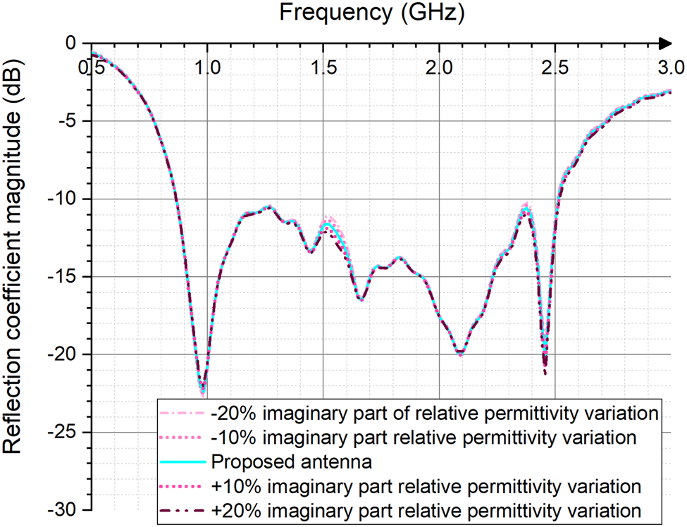
Results shown in Fig. 11 indicate small changes in the |S 11| curves with a ±20% variation in the imaginary part of the relative permittivity of the substrate.
Simulated reflection coefficient magnitude curves versus frequency when antenna substrate is assumed to have a ±20% $\varepsilon _r^{^{\prime\prime}}$ variation.

Effects of change in substrate thickness
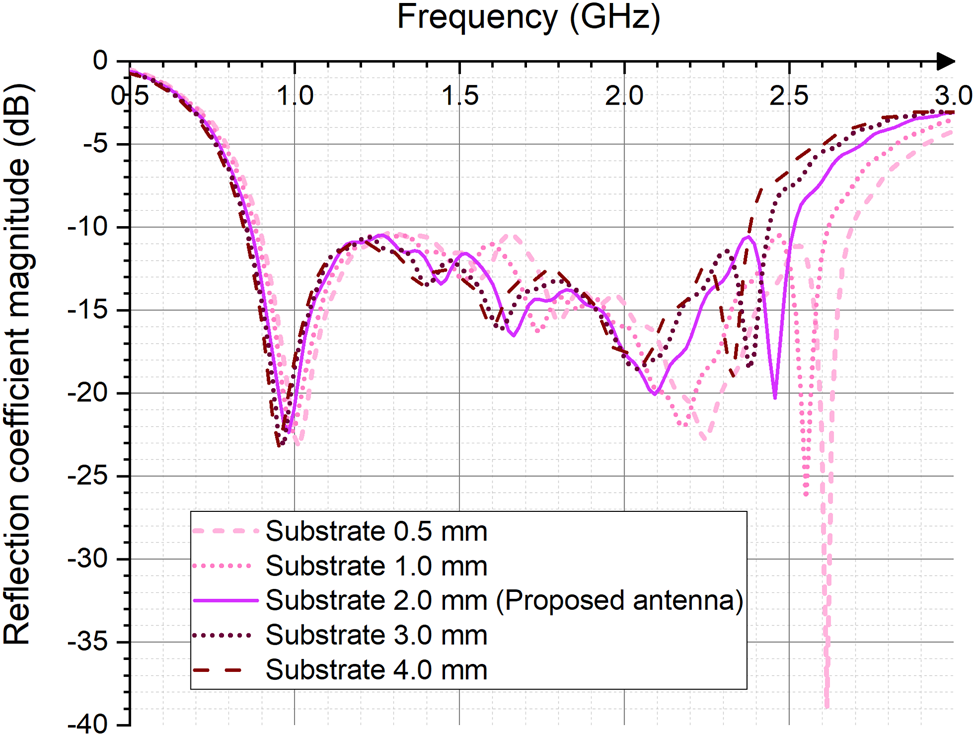
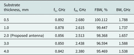
In this subsection, we have also investigated the impact of various substrate thicknesses of the proposed antenna. Figure 12 and Table 3 show the simulated results for the antenna with a substrate thickness of 0.5, 1, 2, 3, and 4 mm, respectively. It is seen that fL and fH decrease with the increase of the thickness of the antenna substrate. It is also observed that the fractional bandwidth changes slightly (from about 100 to 95%) with the substrate thickness. From the bandwidth point of view, the antenna with a substrate thickness of 0.5 mm gives the widest bandwidth. The optimal substrate thickness is found to be 2 mm, with a bandwidth of around 1.66 GHz (from 0.856 to 2.513 GHz) that covers the commonly used wireless communication standards and technologies for IoT applications (see Table 1).
Simulated reflection coefficient magnitude curves versus frequency when antenna substrate is assumed to have a thickness from 0.5 to 4 mm.

Variation in the substrate thickness

Comparison with other previously reported antennas for IoT applications
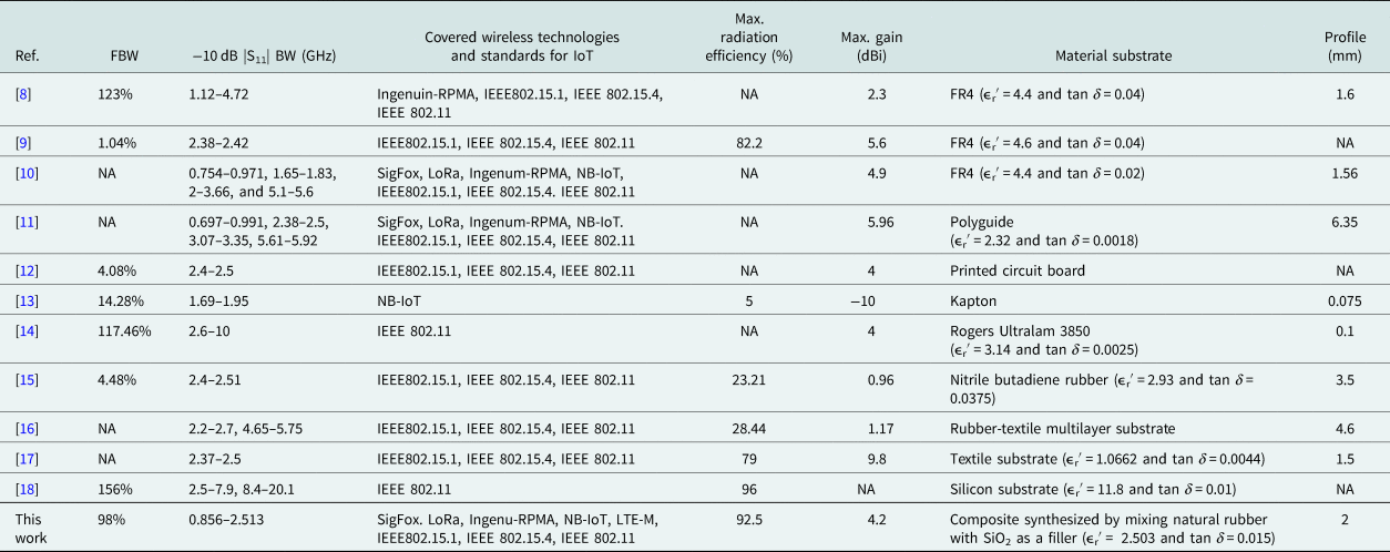
To demonstrate the advantages of the proposed flexible broadband antenna for IoT applications, its performance metric was compared to those of the other previously reported antennas. As a result, one can say that the proposed antenna has better radiation efficiency than [Reference Shafique, Khawaja, Khurram, Sibtain, Siddiqui, Mustaqim, Chattha and Yang9, Reference Damis, Khalid, Mirzavand, Chung and Mousavi13, Reference Al-Sehemi, Al-Ghamdi, Dishovsky, Atanasov and Atanasova15–Reference Atanasov, Atanasova, Stefanov and Nedialkov17], better maximum gain than [Reference Birwal, Singh, Kanaujia and Kumar8, Reference Cheung, Yuen and Mung12–Reference Al-Sehemi, Al-Ghamdi, Dishovsky, Atanasov and Atanasova16], and lower profile than [Reference Bashir, Jha, Mishra, Singh and Sharma11, Reference Al-Sehemi, Al-Ghamdi, Dishovsky, Atanasov and Atanasova15, Reference Al-Sehemi, Al-Ghamdi, Dishovsky, Atanasov and Atanasova16]. Moreover, the proposed antenna has a broader bandwidth than [Reference Shafique, Khawaja, Khurram, Sibtain, Siddiqui, Mustaqim, Chattha and Yang9, Reference Cheung, Yuen and Mung12, Reference Damis, Khalid, Mirzavand, Chung and Mousavi13, Reference Al-Sehemi, Al-Ghamdi, Dishovsky, Atanasov and Atanasova15, Reference Atanasov, Atanasova, Stefanov and Nedialkov17] and covers the most commonly used wireless communication standards and technologies for IoT applications including the SigFox, LoRa, Ingenu-RPMA, NB-IoT, LTE-M, IEEE 802.11, IEEE 802.15.1, IEEE 802.15.4 as presented in Table 4. The inclusion of a rubber composite as the antenna's substrate and a conductive fabric as the antenna's radiating elements leads to better mechanical robustness and more flexibility of the proposed antenna and represents key advantages for IoT applications. Other advantages of the proposed antenna are the low-cost and simple fabrication process.
Comparison between the proposed antenna performance and other reported antennas

Conclusion
In conclusion, this paper has demonstrated the detailed design and development of a novel flexible broadband antenna with high radiation efficiency. From the simulation studies, the overall size of the antenna, including the CPW feed line is found to be 0.26 λ 0 × 0.32 λ 0 × 0.006 λ 0, where λ 0 is the free space wavelength at 0.856 GHz (92 mm × 121.5 mm × 2 mm). The proposed antenna shows −10 dB impedance bandwidth of 98.4% (0.856–2.513 GHz) with more than 75% radiation efficiency for the entire frequency range. An antenna prototype was fabricated and tested, showing a good agreement between measured and simulated results. The effects of bending on the antenna performance have also been investigated. The presented results for measured reflection coefficient magnitude curves demonstrate that bending has a minor effect on the antenna impedance bandwidth. Reliable electrical and mechanical performance of the designed antenna makes it a possible candidate for IoT applications.
Acknowledgement
The authors would like to acknowledge the support of the King Khalid University for this research through grant # RCAMS/KKU/005-19 under the Research Center for Advanced Materials Science at King Khalid University, Kingdom of Saudi Arabia.
 Abdullah G. Al-Sehemi is a Professor in the Department of Chemistry at King Khalid University, Saudi Arabia. He received his Ph.D. degree from the University of Leicester, UK. He is currently a Member of the Saudi Consultative Council. He was the Dean of Scientific Research and Director of The Research Center for Advanced Materials Science (RCAMS). He is the author of over 200 publications, co-inventor of several patents, and the editor of six books. He is working experimentally and computationally in the field of advanced functional materials, nanomaterials, stereochemistry, and drug design.
 Ahmed A. Al-Ghamdi is a staff member at King Abdul Aziz University (KAU), Faculty of Science, Physics Department. He obtained his B.Sc. degree in Physics from KAU in 1981 and Master's degree in 1985 from Tulane University, USA. The Ph.D. degree was obtained in 1990 from Sussex University, UK, in point defects created by ion implantation. He has 26 years of experience in academic and research activities in solid-state physics. He worked in various fields of solid physics applications including photodiodes, gas sensors, biosensors, and various other fields of applications. He is currently working in synthesis, characterization, and applications of composites and nanocomposites.
 Nikolay T. Dishovsky received the Ph.D. degree from the University of Chemical Technology and Metallurgy, Sofia, in 1983 and the Doctor of Science Degree from the same university in 1997. Since 2000 he is a full professor and a head of Department of Polymer Engineering at the University of Chemical Technology and Metallurgy. He is the author of eight books, more than 230 articles, and more than 45 patents for inventions. Prof. Dishovsky was a recipient of the Bulgarian Patent Office award for the inventor of the year 2015. His research interests include fillers and filled elastomers, rubber-based nanocomposites, rubber-based sensors, and microwave absorbers.
 Gabriela L. Atanasova received the M.Sc. and Ph.D. degrees from the Technical University of Sofia, Sofia, Bulgaria, in 1999 and 2013, respectively. She currently is an Associate Professor with the Department of Communication and Computer Engineering and Vice-Dean for the Faculty of Engineering, South-West University “Neofit Rilski”, Blagoevgrad, Bulgaria. Her research interests encompass theoretical and experimental studies for modeling interactions between EM fields and biological systems, as well as methods for the computer-aided analysis and design of high-frequency structures and antennas.
 Nikolay T. Atanasov received the M.Sc. and Ph.D. degrees from the Technical University of Sofia, Sofia, Bulgaria, in 1999 and 2013, respectively. He is currently an Associate Professor with the Department of Communication and Computer Engineering, South-West University “Neofit Rilski”, Blagoevgrad, Bulgaria. He is also a Vice-Director of the Electromagnetic Compatibility Laboratory at Bulgarian Institute of Metrology, Sofia, Bulgaria. His research interests include computational electrodynamics, SAR computation, design of antennas for wireless devices, medical diagnostic and therapeutic applications of EM. He is particularly interested in the characterization of the electromagnetic properties of materials at microwave frequencies and the investigation of the potential of conductive composites for antenna applications.