Introduction
Power dividers are essential circuits in modern wireless systems such as radar systems, commercial communications, and satellite communications. Various power dividers with small size based on microstrip line structures have recently been reported [Reference Gupta, Gabdrakhimov, Dabarov, Nauryzbayev and Hashmi1–Reference Zhu and Guo3]. However, as the operating frequency has increased, e.g. at millimeter-wave frequency band, microstrip line power dividers suffer from high insertion loss. Waveguide power dividers have the merits of high-power capability, good heat-sinking, and so on. Substrate-integrated waveguide (SIW) power dividers show advantages of compact size, and easy connection with planar circuits. Recently, a great number of waveguide and SIW power dividers have been developed.
It is well known, reciprocal lossless T-junctions, including bifurcated waveguide, magic-T, and waveguide T-junctions, are inherently mismatched. So, additional approaches should be developed to obtain good performance at all ports. In the E-plane bifurcated waveguide power divider design [Reference Liu, Niu and Li4], a resistive film was placed in the E-plane to improve the isolation performance. Similarly, an SIW power divider with the same design concept was proposed in [Reference Pasian, Silvestri, Rave, Bozzi, Perregrini, Jacob and Samanta5]. A magic-T has four arms which are mostly located in four different directions. Matching elements, like a cone, wedge, pin, and iris were used to achieve port matching. In [Reference Hwang6], a broadband waveguide magic-T junction is presented. A multi-stepped, off-centered conducting cone was optimized by genetically swarm optimization technique to expand the bandwidth. In [Reference Chu, Wu and Mo7], a magic-T with four arms in the same plane was proposed. The E-plane port matching was achieved by a stepped-impedance waveguide transformer and the H-plane port is realized by a microstrip impedance transformer. Similarly, a magic-T with coplanar arms was developed in [Reference Guo, Li, Huang, Shao, Ba, Jiang, Jiang and Deng8]. The H-plane sum port was realized by a ridge waveguide coupling structure. The two difference ports were realized by two half-height waveguides. And the corner cut was especially shaped to improve the return loss performance. However, the transition between the coaxial and half-height waveguide narrowed the operating bandwidth.
For the traditional waveguide T-junction, it is the most common waveguide power splitter with the advantages of small size, wide bandwidth, low insertion loss, and easy fabrication, but the isolation performance between two output ports should be improved. So far, many kinds of waveguide T-junctions were investigated. In [Reference Zhao, Wang, Tian and Wang9], a planar waveguide T-junction power divider with equal-amplitude, anti-phases, and full bandwidth was presented. Three-stepped-impedance transformer and some ridges were added between the coupling cavity and each port to expand the operation bandwidth. However, no measures were taken to improve the isolation performance. In [Reference Xu, Xu, Cui and Qian10], a waveguide T-junction power divider with good performance was proposed. Isolation between two output ports was realized by introducing a metallic strip probe into the center of the T-junction, the energy coupled by the probe is absorbed by a matched load. Two power dividers which share this similar design concept were proposed in [Reference Gouda, López, Desmaris, Meledin, Pavolotsky and Belitsky11, Reference Dang, Zhang, Zhu, Yan and Xu12]. In [Reference Ding, Wang, Zhang and Wang13], a waveguide power divider was realized by properly arranging the configuration and dimensions of the coupling region to control the propagation constants of TE10 and TE30 modes. There was no resistive material between two output ports, and the isolation was realized by two waveguides adjacent to the input port. An SIW power divider which shares a similar design strategy was presented in [Reference Huang, Jiang, Jin, Zhou, Leng, Wang and Wu14].
Except in [Reference Dang, Zhang, Zhu, Yan and Xu12], the output ports of the waveguide power dividers mentioned above are waveguide. Therefore, additional transition between waveguide and planar transmission line is needed to connect other planar circuits, which will increase the insertion loss and complexity of the circuits. Moreover, although the output ports of the SIW power dividers [Reference Djerafi, Hammou and Wu15, Reference Vincenti Gatti and Rossi16] are planar, the isolation is not high, which restricts its applications in some areas.
In this paper, a high-isolation power divider with waveguide input port and two planar output ports is presented. It shows the merits of planar output ports, high isolation, and compact size. It can be utilized in a short-range frequency-modulated continuous wave (FMCW) system depicted in Fig. 1, as the proposed power divider shows three distinct advantages as follows:
(1) The isolation performance of the proposed power divider is much higher than the conventional circulator whose isolation may not satisfy certain system requirement.
(2) Based on the proposed vertical transition between ridge waveguide and microstrip line, the planar microstrip antenna array can be integrated with the waveguide port of the proposed power divider directly, resulting in a higher system integration level.
(3) Because the output ports are planar, active devices such as PA and low noise amplifier (LNA) in Tx and Rx channels can connect directly with port 2 and port 3, respectively, further improving the system integration level.
Block diagram of an FMCW system using the proposed power divider.

In Fig. 1, the traditional circulator is substituted by the proposed power divider. The Tx signal leaked into LNA through the isolation path is utilized as the local oscillator (LO) signal of the single-ended mixer whose LO signal is fed into the same port with radio-frequency signals.
Analysis of the proposed power divider
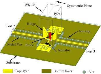
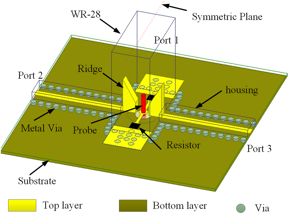
Figure 2 depicts the configuration of the proposed power divider. It consists of a standard WR-28 waveguide as the input port, two microstrip line output ports, and an insulator. The ridge waveguide, function as an impedance transformer between waveguide and planar transmission line, is hidden in the standard waveguide, so the whole circuit size is more compact than the circuit in [Reference Xu, Xu, Cui and Qian10–Reference Dang, Zhang, Zhu, Yan and Xu12] in which the impedance transformation is accomplished by stepped-impedance waveguide. The isolation between two output ports is realized by an insulator which is inserted into the junction from the bottom of the substrate. Two chip resistors connect with the insulator by two microstrip lines which are also hidden in the waveguide, whereas the isolation circuits in [Reference Chu, Wu and Mo7, Reference Guo, Li, Huang, Shao, Ba, Jiang, Jiang and Deng8, Reference Xu, Xu, Cui and Qian10–Reference Ding, Wang, Zhang and Wang13] are exposed outside which results in a large circuit size. The substrate used in this circuit is Rogers RT/Duroid 5880 with a thickness of 0.254 mm, loss tangent of 0.0009, and relative dielectric constant of 2.2.
Configuration of the proposed power divider.
The proposed power divider is developed from waveguide E-type T-junction, so its operational principle can be explained by waveguide E-type T-junction. Figure 3 shows the structure of the waveguide E-type T-junction, the electric field of the propagated TE10 mode is depicted in Fig. 3(b). It is well known that the signal can be propagated only when the electric field direction on the rectangular waveguide wide side is opposite. When ports 2 and 3 are fed by the same amplitude and in-phase signal sources (even-mode excitation), the rectangular waveguide TE10 mode in port 1 cannot be excited under this condition. Thus, there is no signal transmitted to port 1. However, the energy can be coupled to the probe and then be absorbed by chip resistors, thus good isolation can be obtained. When the two output ports are fed by signal sources with equal amplitude and anti-phase (odd-mode excitation), the rectangular waveguide TE10 mode in port 1 is excited under this condition, and no energy is absorbed by chip resistors as the energy coupled to the probe is canceled with each other, resulting in most of the energy is delivered to port 1. According to the analysis above, the scatter parameters of the power divider can be summarized as

Structure of the waveguide E-type T-junction: (a) structure and (b) electric field distribution.

According to the even- and odd-method [Reference Pozar17], the S-parameters of this proposed power divider can be expressed as


where Γo 1 and Γo 2 are the reflection coefficients at ports 1 and 2 when the whole circuit is under odd-mode excitation, respectively. Γe 2 is the reflection coefficient at port 2 when the whole circuit is under the even-mode excitation.
Vertical transition between waveguide and microstrip line
As shown in equation (2), it can be seen that matching at port 1 is determined by the odd-mode reflection coefficient which is mainly determined by the dimensions of the ridge waveguide. Figure 4 shows the physical dimension of the ridge waveguide to microstrip line. For the simplicity of design, the ridge waveguide has the same width as the microstrip line. The microstrip line is surrounded by housing with waveguide modes free and mechanical protection. The inner dimension of the housing is chosen as 0.7 mm × 2 mm. Under this shielding house, the width of 50 Ω transmission line is 0.75 mm. To achieve a good impedance matching over broad frequency band, stepped ridge waveguide is applied. The triangle shape of the ridge waveguide used in this circuit is for the fabrication concern. Figure 5 depicts the simulated results of the return loss of port 1 when h 1 = 0.78 mm and h 2 changes. It shows that the ridge height has a great impact on the return loss of port 1, validating the equation in (2).
Transition between waveguide and microstrip line: (a) side view and (b) top view.

Simulated results of the input return loss with varying h 2.

Isolation between two output ports
Figure 6 shows the configuration of the planar circuit and insulator. Physical dimensions of the probe are d 1 = 0.38 mm, d 2 = 2.7 mm, l 1 = 2.04 mm, and l 2 = 1.5 mm. To minimize the whole circuit, one end of the probe is cut-off when the insulator is utilized in the proposed power divider. The height of the probe (l 1) is about quarter-wavelength at the central operating frequency. The insulator inserts from the bottom of the substrate, as shown in Figs 6(b) and 6(c). To avoid shorting the probe, a circular metal on the backside of the substrate is removed, as shown in Fig. 6(c). Its diameter is chosen as 1.5 mm in this proposed Ka-band power divider, which is larger than d 1 and smaller than d 2. The probe connects with the microstrip line at the top layer of the substrate. Another end of the microstrip line is connected with the chip resistor. As the chip resistor's power capacity is directly proportional to its value, the value of the chip resistor is selected as 100 Ω in this proposed circuit.
Configuration of the planar circuit and insulator: (a) insulator, (b) side view, and (c) top view.

Figure 7 shows the simulated output return loss and isolation under different characteristic impedances of the microstrip line when the chip resistor's value is fixed at 100 Ω. It can be observed that the characteristic impedance has a great influence on the output return loss and isolation. This can be explained by equations (4) and (5), the output return loss and isolation are relevant with Γe 2 which is affected by the isolation circuit.
Simulated results of the power divider under different characteristic impedance: (a) S 23 and (b) S 22.

Since the chip resistors are mounted on the substrate and surrounded by the waveguide, physical dimensions of the chip resistor should be considered. The dimension of the standard Ka-band waveguide is 3.556 mm × 7.112 mm, and the chip resistor's dimension used in this circuit is 1.6 mm × 0.8 mm × 0.5 mm. As shown in Fig. 6(c), the total length of the microstrip line and two chip resistors may exceed the length of the waveguide (7.112 mm). Moreover, as the narrow side of the waveguide does not influence on the propagation of TE10 mode in the waveguide, two housings on the narrow side are dug to assemble the chip resistors. The dimensions of the housing are 2.5 mm × 2.2 mm × 1.5 mm.
Experiment and discussion
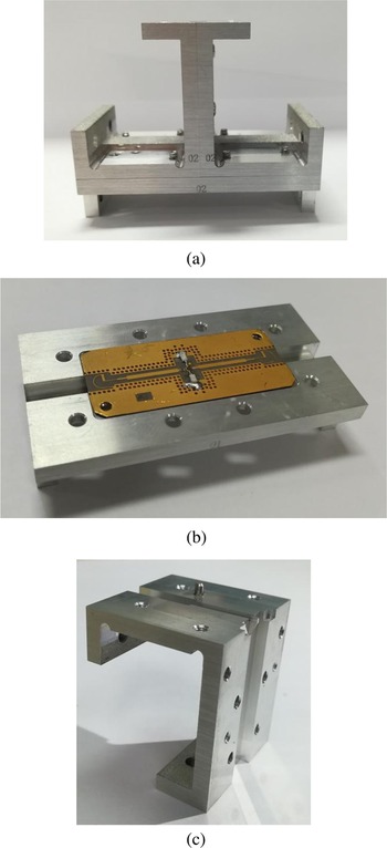
In order to validate the proposed design concept, a power divider operating at the Ka-band is simulated, fabricated, and measured. For the convenience of measurement, two microstrip-to-waveguide transitions [Reference Tang, Pan, Cheng and Lin18] are cascaded to the planar output ports. The planar circuits are etched on the top layer of a Rogers RT/Duroid 5880 substrate. Two Vishay 100 Ω thin-film chip resistors are soldered between the microstrip line and grounding pad. The whole power divider consists of four parts, i.e. three cavities and a planar substrate. The planar substrate is sustained by the bottom cavity. Figure 8 shows photographs of the fabricated waveguide power divider. For the simplicity of fabrication, the whole cavity is divided into three parts, i.e. left-side cavity, right-side cavity, and the bottom cavity. The left-side and the right-side cavities are symmetrical, which are bisected from the narrow side of the WR-28 waveguide.
Photographs of the fabricated power divider: (a) whole circuit, (b) planar circuit and bottom cavity, and (c) cavity of the left side.

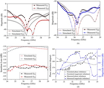
The circuit is measured by using an Agilent N5244A network analyzer. Comparisons between the simulated and measured results are shown in Fig. 9. It can be seen that from 34 to 39 GHz, the insertion loss including waveguide-to-microstrip transition at the output port is <1.5 dB, the isolation is better than 20 dB, and the return loss of three ports is better than 10 dB. The phase deviation of two outputs is in the range of 178.3–181.3°, and the magnitude imbalance is <0.5 dB. Especially, in the range of 36.2–37.2 GHz, the isolation between two output ports are better than 40 dB, and the return loss of three ports is better than 21, 19.8, and 20.8 dB, respectively.
Comparisons between the simulated and measured results of the proposed power divider: (a) S 11, S 21, and S 23, (b) S 22 and S 23, (c) insertion loss, and (d) magnitude and phase imbalance.

Table 1 shows comparisons between the proposed power divider and the previously reported ones. It can be observed that the proposed circuit has excellent isolation performance, especially when considering the isolation better than 40 dB, only the circuits in [Reference Hwang6, Reference Chu, Wu and Mo7] can achieve this level. However, their isolation bandwidths are relatively narrow. Moreover, the output ports of the circuits in [Reference Hwang6–Reference Gouda, López, Desmaris, Meledin, Pavolotsky and Belitsky11, Reference Ding, Wang, Zhang and Wang13] are rectangular waveguide ports, which is inconvenient to integrate with other planar circuits such as power amplifiers, low noise amplifiers, and so on. Furthermore, the impedance-transformation stages in [Reference Chu, Wu and Mo7–Reference Gouda, López, Desmaris, Meledin, Pavolotsky and Belitsky11] are based on waveguide stepped-impedance transformers, and the isolation circuits in [Reference Chu, Wu and Mo7, Reference Guo, Li, Huang, Shao, Ba, Jiang, Jiang and Deng8, Reference Xu, Xu, Cui and Qian10–Reference Ding, Wang, Zhang and Wang13] are exposed outside. These drawbacks create a hurdle to further improve the circuit's integration level and result in a large circuit size. However, in this proposed power divider, the output ports are planar and the isolation part is hidden in the waveguide. So, it can be concluded that the proposed power divider shows advantages of compact size, planar output port, and easy integration with other circuits when compared with the power dividers in [Reference Hwang6–Reference Gouda, López, Desmaris, Meledin, Pavolotsky and Belitsky11, Reference Ding, Wang, Zhang and Wang13]. When compared with the power dividers in [Reference Pasian, Silvestri, Rave, Bozzi, Perregrini, Jacob and Samanta5, Reference Guo, Li, Huang, Shao, Ba, Jiang, Jiang and Deng8–Reference Vincenti Gatti and Rossi16], the proposed power divider has the merits of high isolation.
Comparisons between the proposed power divider and previously reported ones

a Estimated.
b Including insertion loss of waveguide-to-microstrip transition at two output ports.
Conclusion
A Ka-band waveguide power divider with planar output ports, compact size, and high isolation is proposed in this paper. Vertical transition between ridge waveguide and microstrip line is utilized to realize planar output ports in order to integrate with other planar circuits directly. To realize high isolation between two output ports, a probe insulator is inserted through the bottom cavity and substrate to couple the energy between two output ports, and the unwanted energy is absorbed by two chip resistors. As the ridge waveguides, probe, and chip resistors are hidden in the waveguide, so the whole circuit is very compact. For verification, a prototype power divider is simulated, fabricated, and measured. The measured results agree well with the simulated ones, which verify the validity of the proposed design concept. Comparisons between previously reported works indicate that the proposed work shows merits of waveguide power divider and SIW power divider simultaneously.
 Cong Tang was born in Shangqiu, Henan Province, China. He received his B.S. degree in electronic engineering from PLA Information Engineering University, Zhengzhou, China in 2010, and his Ph.D. degree from the UESTC (University of Electronic Science and Technology of China), Chengdu, China in 2018. From 2020, he joined the Southwest China Institute of Electronic Technology. His research interests include millimeter-wave and microwave circuits and systems.
 Xin Gao received his B.S. degree in electronic engineering from Northwest University, Xi'an, Shaanxi, China, in 1995, his M.S. degree in optics engineering from Northwestern Polytechnical University, Xi'an, in 1998, and his Ph.D. degree in optics engineering from the Xi'an Institute of Optics and Precision Mechanics, Chinese Academy of Sciences, Xi'an, in 2007. Currently, he is a Full Professor with the Beijing Institute of Tracking and Telecommunications Technology, Beijing, China. His research interests include design of satellite communication and navigation systems, and phased array signal processing.
 Hongquan Zhu received his Ph.D. degree in physics engineering from Tsinghua University, Beijing, China, in 2008. Since 2008, he is with the Beijing Institute of Tracking and Telecommunications Technology and has involved in the design, construction, and maintenance of Chinese TT&C Stations. Currently, he is an Associate Professor mainly interested in millimeter-wave and microwave circuits and systems.
 Jinrong Zhang received her B.S. degree and master degree in electronic engineering from the University of Science and Technology of China, Hefei, China, in 2006 and 2009, respectively. Since 2009, she is with the Beijing Institute of Tracking and Telecommunications Technology and has involved in the design, construction, and maintenance of Chinese TT&C Stations. Currently, she is an assistant Professor mainly interested in millimeter-wave and microwave circuits and systems.